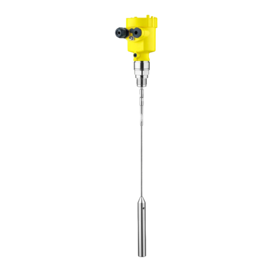
Vega VEGAFLEX 81 Mounting Instructions
Shipbuilding
Hide thumbs
Also See for VEGAFLEX 81:
- Operating instructions manual (100 pages) ,
- Quick setup manual (24 pages) ,
- Supplementary instructions manual (24 pages)
Summary of Contents for Vega VEGAFLEX 81
- Page 1 Mounting instructions - Ship- building VEGAFLEX 81 Cargo tank (crude oil) Waste oil tank Service tanks (heavy oil, cooling water tank) Ballast tanks (wing tanks) Document ID: 39154...
-
Page 2: Table Of Contents
Installation on deck without protective cover ..............7 Mounting - standard Actuating variables ......................8 Distance to vessel installations..................11 Ways of fastening the probe ................... 14 Mounting in a standpipe Mounting - cable version ....................17 Editing status: 2013-06-11 VEGAFLEX 81 • Cargo tank (crude oil) -
Page 3: General Information
To ensure proper functioning of the instrument, take careful note of all the information in this mounting instructions manual. Mount the VEGAFLEX 81 exactly according to the instructions in this manual. Read this manual before selecting the mounting position. Take note of existing installations and discuss the mounting with the shipyard technicians. - Page 4 10 Order number 11 Serial number of the instrument 12 Symbol of the device protection class 13 ID numbers, instrument documentation 14 Reminder to observe the instrument documentation 15 Notified authority for CE marking 16 Approval directives VEGAFLEX 81 • Cargo tank (crude oil)
-
Page 5: Measuring Range
Probe length L Measuring range (default setting refers to the measuring range in water) Upper dead band (in this area no measurement is possible) Lower dead band (in this area no measurement is possible) VEGAFLEX 81 • Cargo tank (crude oil) -
Page 6: Mounting, In General
Aluminium die- casting Stainless steel housing 316L (IP 68, 0.2 bar) Cable gland for cable diameters of 7 … 12 mm. An additional seal for cable diameters of 10 … 14 mm is attached. VEGAFLEX 81 • Cargo tank (crude oil) -
Page 7: Installation On Deck Without Protective Cover
9 … 11 mm is attached. Stainless steel housing IP 68, 1 bar Fig. 15: Housing stainless steel, precision casting 316L IP 68, 1 bar with VEGA cable outlet Stainless steel housing IP 68, 1 bar with cable outlet (PUR) and capil- laries for pressure transmitters. VEGAFLEX 81 • Cargo tank (crude oil) -
Page 8: Mounting - Standard
Installations within this energy field influence the measurement. Process fitting If possible, avoid vessel sockets. Mount the sensor flush to the vessel ceiling. If this is not possible, use short sockets with small diameter. VEGAFLEX 81 • Cargo tank (crude oil) - Page 9 If a socket is required, you can find the optimised dimensions d and h in the following table. DN 50 … DN 150 150 mm (5.91 in) DN 150 … DN 200 100 mm (3.94 in) VEGAFLEX 81 • Cargo tank (crude oil)
- Page 10 3 Mounting - standard Mounting details of the socket Fig. 18: Mounting details of the socket VEGAFLEX 81 • Cargo tank (crude oil)
-
Page 11: Distance To Vessel Installations
Keep a min. distance to vessel installations or the vessel wall to avoid adverse effects on the measurement. The probe must not touch installations or the vessel wall during operation. If necessary, secure the probe end. VEGAFLEX 81 • Cargo tank (crude oil) - Page 12 3 Mounting - standard Distance to the vessel wall and to frame profiles ≥ 300 mm (11.81") ≥ 300 mm ≥ 300 mm (11.81") (11.81") Fig. 20: Avoid interference from the vessel wall and frame profiles Vessel wall 2 Frames, reinforcement profiles, etc. VEGAFLEX 81 • Cargo tank (crude oil)
- Page 13 Filling stream Distances with strain relief ≥ 300 mm (11.81") Fig. 22: Strain relief - distances to frame profiles on the vessel bottom Frame Sensor cable 3 Configuration of the strain relief, side view Keep a min. distance to heating coils in the vessel to avoid adverse effects on the measurement. VEGAFLEX 81 • Cargo tank (crude oil)
-
Page 14: Ways Of Fastening The Probe
Fig. 24: Heating coils - side view Heating coil Sensor cable 3 Gravity weight Ways of fastening the probe The min. level min depends on the height of the mounting facility z and the offset of the medium y. VEGAFLEX 81 • Cargo tank (crude oil) - Page 15 Strain relief - horizontal min level Fig. 26: Mounting version horizontal, side view Pulley 2 Gravity weight Tension bolt Spring Threaded rod for straining y Offset Height of the fastening arrangement Medium Water 10 mm (0.79 in) VEGAFLEX 81 • Cargo tank (crude oil)
- Page 16 The value y states the min. lower value of the measuring range. This value depends on the medium. Add the height of the mounting facility z and the offset of the medium y, to calculate the total dead band. VEGAFLEX 81 • Cargo tank (crude oil)
-
Page 17: Mounting In A Standpipe
Standpipe mounting with gravity weight and spring 3 Standpipe mounting with gravity weight and centering disk The sensor cable must be tightly stretched with a gravity weight or spring. The measurement will not function if the sensor cable touches the inner wall of the standpipe. VEGAFLEX 81 • Cargo tank (crude oil) - Page 18 The value y states the min. lower value of the measuring range. This value depends on the medium. Add the height of the mounting facility z and the offset of the medium y, to calculate the total range that cannot be measured. VEGAFLEX 81 • Cargo tank (crude oil)
- Page 19 Notes VEGAFLEX 81 • Cargo tank (crude oil)
- Page 20 Subject to change without prior notice © VEGA Grieshaber KG, Schiltach/Germany 2013 VEGA Grieshaber KG Phone +49 7836 50-0 Am Hohenstein 113...


Need help?
Do you have a question about the VEGAFLEX 81 and is the answer not in the manual?
Questions and answers