Table of Contents
Advertisement
Advertisement
Table of Contents

Related Manuals for Sena Parani-SD1000


Summary of Contents for Sena Parani-SD1000
-
Page 1: User Guide
Parani-SD1000 User Guide Version 1.0.2 2009-1-21... - Page 2 This device is not approved for life-support or medical systems. Changes or modifications to this device not explicitly approved by Sena Technologies will void the user's authority to operate this device.
-
Page 3: Revision History
Revision History Revision Date Name Description V1.0.0 2008-09-25 Cp Moon Initial Writing V1.0.1 2008-10-24 Marc Woo Revision V1.0.2 2009-01-21 WJ Kim Revision... -
Page 4: Table Of Contents
1.3. Product Specification ......................8 2. Getting Started 2.1. Panel Layout ........................10 2.2. Connecting the Hardware ....................10 2.2.1. Connecting Power to Parani-SD1000 ............... 10 2.2.2. Connecting Device to Parani-SD1000 ...............11 2.2.3. Attaching Battery Pack to Parani-SD1000..............11 3. Configuration 3.1. - Page 5 B.1.4. Operation Status ..................... 29 B.1.5. Security........................29 B.1.6. Symbols........................30 B.2. Command Category ......................30 B.3. Command Description ....................... 31 B.3.1. ATZ ........................31 B.3.2. AT&F ........................31 B.3.3. AT ......................... 31 B.3.4. AT+UARTCONFIG,Baudrate,Parity,Stopbit ............. 31 B.3.5. AT+USEDIP? ......................32 B.3.6.
- Page 6 D.3. Transmission Delay......................44 D.3.1. RF Processing Delay....................44 D.3.2. RF Transmission Environment................. 44 Appendix E: Parani-SD1000 mechanical drawing E.1. Parani-SD1000 mechanical drawing (mm) ................. 45 E.2. Battery pack mechanical drawing (mm) ................46 Appendix F: Warranty F.1. GENERAL WARRANTY POLICY ..................47 F.2.
-
Page 7: Introduction
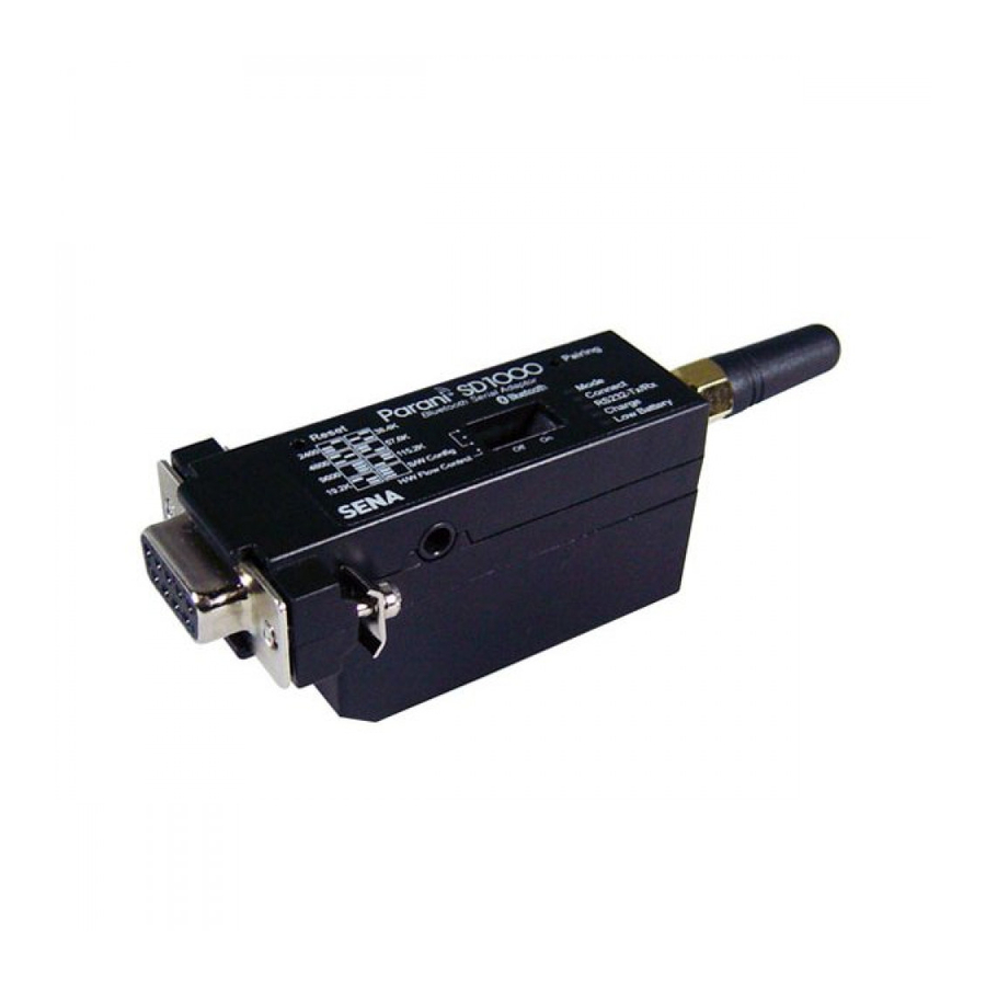
The working distance of Parani-SD1000 with default antenna is 100m Parani-SD1000 has a compact design, which allows it to be placed conveniently into various devices or equipment. Its detachable antenna has the ability to optimize the quality and distance of wireless communications. -
Page 8: Product Specification
1.3. Product Specification Parani-SD1000 Serial Interface One female DB9 serial port for data communication Serial UART speed up to 921.6kbps CTS/RTS flow control, DTR/DSR for loop-back & full transfer Bluetooth Interface Bluetooth v2.0 + EDR Profile: Serial Port Profile Class 1... - Page 9 Environmental Operating temperature: -20 ~ 70 Storage temperature: -40 ~ 85 Humidity : 90% (Non-condensing) Physical properties - Dimension (L x W x H) 76 x 31 x 16 (mm) (No battery pack) 76 x 31 x 19.5 (mm) (with standard battery pack) 76 x 31 x 31.4 (mm) (with extended battery pack) - Weight 24g (No battery pack)
-
Page 10: Getting Started
This section describes how to connect the Parani-SD1000 to the serial device. - Connect a power source to the Parani-SD1000. - Connect the Parani-SD1000 to a serial device. 2.2.1. Connecting Power to Parani-SD1000 Parani-SD1000 can be powered from either external DC power adaptor/external power source, or by... -
Page 11: Connecting Device To Parani-Sd1000
To power the SD1000 from the external DC power adaptor or external power source, connect the power jack to the power connector of the Parani-SD1000 using the DC power adapter, USB power cable or DC power cable that is included in the package. If power is properly supplied, the [Mode] lamp will display a green color. - Page 12 Figure 2-4 Attaching Batter Pack to Parani-SD1000...
-
Page 13: Configuration
SD1000 has connected last. When Parani-SD1000 is initially used or after hardware reset, there is no BD address stored in Parani-SD1000. In this cas e, Mode1 will not be able to work properly. The mode change to Mode1 can be made after Parani-SD1000 succeeds to connect to one other Bluetooth device. -
Page 14: Serial Ports
3.4 Data Bit Parani-SD1000 supports only 8 data bit. In the case of 7 data bit and even/odd parity, use SD 8 data bit and none parity. At this time, master and slave are Parani-SD, Parani-ESD or Parani-MSP series. -
Page 15: Reset To Factory Defaults
When hardware flow control is not being used, the Parani-SD1000 clears the buffer to secure room for the next data when the buffer becomes full. This can mean a loss of data may occur. As the transmission data becomes large, the possibility of data loss becomes greater. -
Page 16: Pairing Button
* Note: You cannot set the Parani-SD1000 to a Baud rate of 1200 and 230K by way of the Dipswitch. If you want to use them, to set these speeds, please configure the dipswitch to S/W Config setting and ParaniWIN commands. -
Page 17: Paraniwin
Run ParaniWIN. Figure 3-2 Serial Port Setting Set each option properly and click [Confirm]. If the settings of the Parani-SD1000 are different from the ParaniWin, an error message will pop up. If the Parani-SD1000 is in the status of connection, warning message will pop up. - Page 18 Figure 3-5 Menu Bar at Upper Left corner of ParaniWIN When the ParaniWin software is able to access the Parani-SD1000 properly, the icons in the left side window come will become available for use. In device configuration window, hardware reset can be executed or operation mode and RS232 can...
- Page 19 Master and Slave use the Encryption option. Parani-SD1000 has 4 response messages, ‘ OK’ , ‘ ERROR’ , ‘ CONNECT’ , and ‘ DISCONNECT’ . In some cases, these responses can affect the host system unexpectedly. To prevent this, user can set the Command response to ON or OFF.
- Page 20 Figure 3-7 Connection (out) Window Click [Search] button to search nearby Bluetooth devices. Once several Bluetooth devices has been found, select one of the devices and click the [Connect] button. The selected Bluetooth device must be discoverable and connectable. Click [Disconnect] button to cancel the connection. After the connection has been established, you will be able to test signal strength by pushing the START button.
- Page 21 The signal strength test shows LInkQuality and RSSI values. The closer LinkQuality is to 255 and RSSI is to 0, this means the Parani-SD1000 has a good connection to the connected Bluetooth device. In general, the wireless connectivity is at its best within 10 meters. You can push the STOP button at anytime in order to terminate the signal strength test.
-
Page 22: Paraniupdater
Step 3. Disconnect SD2, once again connect SD1 and then push the Finish button. The pairing configuration should be completed. Make sure that each Parani-SD1000’ s connect LED is on. At this point, when both Parani-SD1000’ s restart the connection will be established automatically. -
Page 23: Terminal Program
A terminal program is typically an application that will enable a PC to communicate directly with a modem. If you are using Windows 98SE or higher version of Windows, HyperTerminal program is included as part of the operating system. Parani-SD1000 provides some extended AT commands for configuration of the Parani-SD1000. - Page 24 Make sure that the Connect LED is turned off and the Stanby LED is turned on before attempting to send any kind of AT commands to the Parani-SD1000. Then launch HyperTerminal, it can usually be found in start >programs >accessories >communication >HyperTerminal. Select the Serial port that Parani-SD1000 is connected to.
-
Page 25: Approval Information
4. Approval Information 4.1. FCC 4.1.1. FCC Compliance Statement This device complies with part 15 of the FCC Rules. Operation is subject to the following two conditions: (1) This device may not cause harmful interference, and (2) This device must accept any interference received, Including interference that may cause undesired operation 4.1.2. -
Page 26: Rf Information
GFSK (Gaussian-filtered Frequency Shift Keying) Pi/4 DQPSK (pi/4 rotated Differential Quaternary Phase Shift Keying) 8DPSK (8 phase Differential Phase Shift Keying) 5.5. Radio Output Power Products Radio Output Power Parani-SD1000 +18dBm 5.6. Receiving Sensitivity Products Radio Output Power Parani-SD1000 -88dBm 5.7. -
Page 27: Appendix A: Connections
Appendix A: Connections A.1. Serial Port Pin Outs Parani-SD is a DCE device compatible with the RS232 standard, a DB9 female interface. Figure A-1 Pin layout of the DB-9 female connector Table A-1. Pin assignment of the DB- 9 female connector Pin # Signal Direction... -
Page 28: Serial Wiring Diagram
A.2. Serial Wiring Diagram A.2.1. To Host with DTE Interface A.2.2. To Host with DCE Interface... -
Page 29: Appendix B: At Commands
Appendix B: AT Commands B.1. Terminology B.1.1. AT Command AT command set is the i n fact standard language for controlling modems . The AT command set was developed by Hayes and is recognized by virtually all p ersonal computer modems. -
Page 30: Symbols
B.1.6. Symbols The symbols are used for the description of command syntax as follows: Symbols Meaning ASCII Code Carriage return 0x0D Line feed 0x0A Carriage return + Line feed 112233445566 Bluetooth device address N or m One digit decimal number Timeout in seconds B.2. -
Page 31: Command Description
B.3. Command Description B.3.1. ATZ OK Response Purpose Software Reset Description This has the same effects as Powerc ycling the unit. This command disconnects any c onnected Bluetooth device, and stops ongoing tasks. After rebooting, the status will be decided by the preset operation mode. Some AT comm ands require the ATZ command be run s o that the commands can take effect. -
Page 32: At+Usedip
B.3.5. AT+USEDIP? m Response Purpose Check the Baud rate set by the dip switch Description m=0: Dip switches are set to ‘ S/W Config’ m=1: Please view the dipswitches to view your baud rate. Reference AT, ATZ, AT&F, ATS B.3.6. -
Page 33: At+Btver
B.3.9. AT+BTVER? SD1000v1.0.0 Response OK Purpose Display device firmware version Description Display device firmware version Reference AT+BTINFO? B.3.10. AT+BTMODE,n OK Response Purpose Set operation mode Parameters n=0: MODE0 (Default) n=1: MODE1 n=2: MODE2 n=3: MODE3 Description When the operation status is ‘... -
Page 34: Ato
Reference +++, ATO Example AT+SETESC,42 B.3.13. ATO Response None Purpose Convert the operation status of ‘ Standby’to ‘ Connect’ Description You can convert the operation status of ‘ Standby’to ‘ Connect’ready to transmit data. Reference +++, AT+SETESC B.3.14. AT+BTCANCEL OK Response Purpose Term inate the current task... -
Page 35: At+Btscan112233445566,To
Description For the given to, Parani-SD is waiting for the inquiry and connection from other Bluetooth devices. If the parameter of to is 0, it will wait forever. When connection is made with other Bluetooth device, response will be ‘ CONNECT’with its BD address. -
Page 36: Ath
Description Parani-SD attempts to connect to the Bluetooth device with the given BD address. To make successful connection, the Bluetooth device must be in Page scan mode. This attempt continues for 5 minutes. If it fails to make connection, respons e is ‘ ERROR ’ . Reference AT+BTINQ?, AT+BTSCAN Example... -
Page 37: At+Btfp,N
effect the ATZ command must be used or Powercycle the unit. Reference AT+BTFP, AT+BTKEY, AT+BTSD?, AT+BTSEC, ATZ, AT&F B.3.24. AT+BTFP,n OK Response Purpose Set generation of link key every time of c onnection Parameters n=0: Inactivate (Default) n=1: Activate Description If n is set to 1, Parani-SD asks for the pin code every time a c onnection is made. -
Page 38: At+Btrssi,N
n=1: Activate Description During no data transmission, Parani-SD can be in low power mode to save the power. It takes a few seconds to wake the Parani-SD out of low power mode. B.3.28. AT+BTRSSI,n OK Response 0,255,0,0 (repeatedly) Purpose Test signal strength Parameters... -
Page 39: Command Validity
mm= New value of S-register Description Some S-registers are optimized for the overall perform ance and protected and cannot be changed. When users try to c hange thes e S-registers, response is ‘ ERROR’ . For details of S-register, refer Appendix. B. Reference AT&V Example... - Page 40 AT+USEDIP? ○ ○ ○ ○ AT+BTVER? AT+BTRSSI,n ● ◎ Valid only when Parani-SD is not connected to other Bluetooth device. ● Valid only when Parani-SD is connected to other Bluetooth device.
-
Page 41: Appendix C: S-Register
Appendix C: S-Register S-registers contains 52 parameters for the Parani-SD Series. These are stored in flash memory and the values will be saved unless hardware reset is executed. The value of S-register can be accessed and changed with ATS command. Some S-registers not shown below are set to maximize the performance of Parani-SD Series. -
Page 42: S12: Clear Data Buffer When Disconnected (Default 0)
C.7. S12: Clear Data Buffer When Disconnected (default 0) S12=0, Parani-SD does not clear the data buffer when disconnected. S12=1, Parani-SD clears the data buffer when disconnected. C.8. S13: Enable DCD Signal (default 1) S13=0, DCD signal off S13=1, DCD signal on C.9. -
Page 43: S28: Escape Sequence Character (Default 43)
C.15. S28: Escape Sequence Character (default 43) The decimal number of the ASCII code of escape sequence character can be controlled. The initial value is 43, the ASCII code of ‘ +’ . C.16. S31: Page Timeout (default 300) This is the timeout in seconds to attempt connection with the ATD command. After this timeout expires, the Parani-SD will restart automatically. -
Page 44: Appendix D: Trouble Shooting
Appendix D: Trouble Shooting D.1. No Data Transmission D.1.1. COM Port Settings Check whether the Baud rate of Parani-SD matches that of its host equipment. Check whether the host equipment has a Data bit setting of 8. Parani-SD supports only 8 Data bit settings. -
Page 45: Appendix E: Parani-Sd1000 Mechanical Drawing
Appendix E: Parani-SD1000 mechanical drawing E.1. Parani-SD1000 mechanical drawing (mm) 101 with stub antenna 76 without antenna... -
Page 46: Battery Pack Mechanical Drawing (Mm)
E.2. Battery pack mechanical drawing (mm) Standard Battery Pack Extended Battery Pack... -
Page 47: Appendix F: Warranty
(a) any misapplication or misuse of the Product; (b) failure of Customer to adhere to any of SENA’ s specifications or instructions; (c) neglect of, abuse of, or accident to, the Product; or (d) any associated or complementary equipment or software not furnished by SENA. -
Page 48: Software Product Warranty Details
- Replacement of parts due to normal wear and tear, - Hardware has been altered in any way, - Product that has been exposed to repair attempts by a third party without SENA’ s written consent, - Hardware hosting modified SENA Software, or non-SENA Software, unless modifications have been approved by SENA.
Need help?
Do you have a question about the Parani-SD1000 and is the answer not in the manual?
Questions and answers