
Related Manuals for Sena Parani10


Summary of Contents for Sena Parani10
- Page 1 Parani10 Enabling Wireless Serial Communication Users Guide Version 1.0.0 2005-03-07...
- Page 2 This device is not approved for use as a life-support or medical system. Any changes or modifications made to this device without the explicit approval or consent of Sena Technologies will void Sena Technologies of any liability or responsibility of injury or loss caused by any malfunction.
- Page 3 Revision History Revision Date Name Description V1.0.0 2005-03-02 D.H. Shin Initial Release...
-
Page 4: Table Of Contents
3.2 Using a Terminal Program..................... 20 3.2.1 Connecting Parani10 to host 3.2.2 Making the first Parani10/Bluetooth connection 3.2.3 Making Parani10 do INQUIRY SCAN and PAGE SCAN 3.2.4 Releasing the existing Bluetooth connection 3.2.5 Automatic connection of two Parani10 Units 3.2.6 AT command vs. Operational Status 4. - Page 5 C.1 ON/OFF of Hardware Flow Control ..................42 C.2 Enabling/Disabling of Response Signals OK, CONNECT & ERROR ........43 C.3 For DCE connection ......................44 C.4 Hardware Reset ........................44 C.5 How to get Bluetooth CF cards connected to Parani10 ............44...
-
Page 6: Introduction
1. Introduction 1.1 Overview Parani10 is a wireless serial adapter based on Bluetooth technology. It enables the RS232 serial devices to communicate wirelessly throughout the range of 200m ~ 1.2km. It supports both point-to-point connections and point-to-multipoint connections. Users may configure the Parani10 by using an easy-to-use Windows-based utility software or by using a standard AT command set. - Page 7 Fig. 1.2.1 DC Power Cable *Red colored wire of DC power cable is for ‘+’...
-
Page 8: Product Specification
200m Patch Antenna - Default Antenna up to 400m Patch Antenna - Patch Antenna up to 1200m Configuration: Windows Utility, Parani10 Manager Modem AT command set Diagnostic LED: Status and Power LED Power: 4V~12V, minimum 150mA Nominal power consumption of... -
Page 9: Getting Started
Weight 14g Approvals: Bluetooth 1.1 FCC(A), CE, TELEC Warranty: 5-year Limited Warranty 2. Getting Started 2.1 LED Indicators The Parani10 STATUS LED indicates the following: Lamps Description STATUS Amber Standard mode on Parani10 power-up Solid Green Connected to another Bluetooth device... -
Page 10: Rs232 Interface
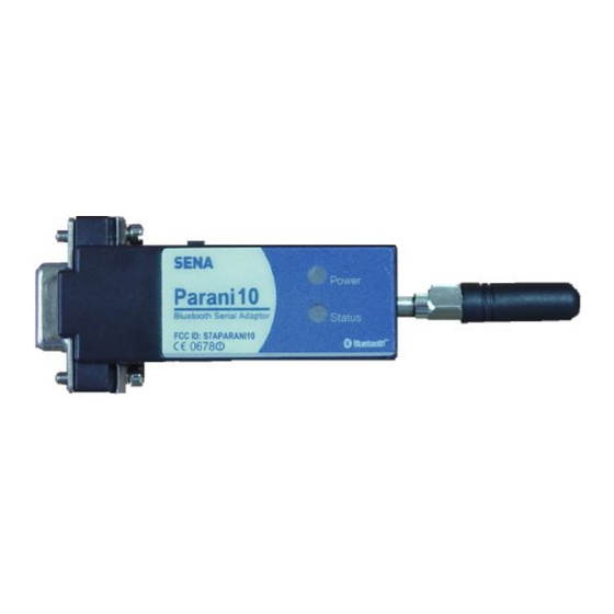
Figure 2.1.1 Parani10 2.2 RS232 Interface Parani10 has a DB-9 (female) connector as shown below in Fig 2.2.1 Figure 2.2.1. DB-9 (Female) • The serial interface is RS232 DCE configured; a DTE device can be connected. • Baud rate: 1200~230400bps •... - Page 11 Output Input Table 2.2.1. Parani10 DB-9 Specification Parani10 is designed to operate as DCE (Data Communications Equipment). To connect to DTE (Data Terminal Equipment), for example a PC or a laptop, a straight cable must be used as in below.
-
Page 12: Connecting Parani10 To Host
ATS14? : To see current status of ATS14. *Default setting of CD line in Parani10 is to show the status of Bluetooth connection. If users want to use CD line to send CDC signal to the other side, such as for a connection between Parani10 and DCE device, users need to configure ATS13. -
Page 13: Configuration
Parani10 automatic connection feature. Once a pair of Parani10’s is set for this feature, they automatically connect whenever powered up. A pair of Parani10 units, within their radio range, may be used as a virtual RS-232 cable. - Page 14 <Fig. 3.1.1> 1-3. Select the number of the Serial port where is attached as in the Fig. 3.1.1 above. 1-4. Users need to select exactly same Baud/Parity/StopBit as real settings of attached P01. 9600/No/OneStopBit are default initial settings of all of Parani10s. 1-5.
- Page 15 1-7. Click the ‘Device Setting’ icon in the list control box. Users may change the Baud rate/Parity/StopBit to meet their individual needs. <Fig. 3.1.3> 1-8. Click the ‘Connection(in)’ icon in list control box. Check both options and then click the START button as shown in Fig.
-
Page 16: Let's Make P02 Search And Connect To P01
1-9. now became ‘Discoverable/Connectable’ so it can receive Bluetooth connection from P02. The STATUS LED of will blink green, twice every 3 seconds. 1-10. Detach from your computer, making sure its status LED is blinking green. 1-11. Close Parani10_Manager. 3.1.2 Let’s make search and connect to P01. -
Page 17: Let's Make Auto-Connection Between P01 And P02
2-8. You will get Successful Connection message. <Fig. 3.1.6> 2-9. Now, Status LEDs on Both are Green, which means they are connected. 2-10. Do not detach from your computer yet, we will go to next stage for Auto-connection (Always-connection). 3.1.3 Let’s make Auto-Connection between 3-1. - Page 18 3-2. Now, Status LEDs of becomes ‘Orange’, as well as P01, as they are disconnected. 3-3. Select Device Setting icon in the list control box, and select MODE1 in Operation Mode and apply. <Fig. 3.1.8> 3-4. Now jobs for are finished. Detach from your computer.
- Page 19 3-7.Select Device Setting icon in the list control box, and select MODE2 in Operation Mode and apply. <Fig. 3.1.9> 3-8. Now, detach from your computer. 3-9. Make sure that power to Both are supplied. With both, and P02, turn off both units using the Switch located on the side of its body. Then, turn on both almost at the same time.
-
Page 20: Using A Terminal Program
3.2 Using a Terminal Program Parani10 units are easily controlled and configured via Parani10_Manager. Likewise, AT command sets are supported by Parani10 to allow device control capabilities used by the terminal program of your choice. 3.2.1 Connecting Parani10 to host For Parani10 use, follow the simple instructions below: 1. -
Page 21: Making Parani10 Do Inquiry Scan And
Enter ‘ATD’ command in the BD_ADDR of any Bluetooth device for connection. During the connection process, the STATUS LED will flash green every second. 4. The Parani10 returning a ‘CONNECT’ message and displaying a green STATUS LED indicates connection. ATD000B53000080 CONNECT 3.2.3 Making Parani10 do INQUIRY SCAN and PAGE SCAN... -
Page 22: Releasing The Existing Bluetooth Connection
3 seconds until it is connected to another Bluetooth device. AT+BTSCAN 3. Try Bluetooth connection to the Parani10 from the other Bluetooth device. Once connected the first Parani10 will return the ‘CONNECT’ message and the STATUS LED will display a continuous green without flashing. -
Page 23: Automatic Connection Of Two Parani10 Units
1. Set one Parani10 to do INQUIRY SCAN and PAGE SCAN operation as directed in section 3.2.3. 2. Set the other Parani10 to connect to the Parani10 in the previous step. 3. Once connected successfully, both Parani10 units store the BD_ADDR of... -
Page 24: At Command Vs. Operational Status
Flash. When desired, release the connection as directed in section 3.2.4. 4. Set the operating mode of one Parani10 to MODE 1 by entering an ‘AT+ BTMODE’ command as shown below. AT+BTMODE,1 5. Set the operating mode of the other Parani10 to MODE 2 by entering an ‘AT+BTMODE’... - Page 25 1) Effective when Parani10 is not in connection with Bluetooth. 2) Effective when Parani10 is in connection status with Bluetooth. 3) Recommend to be used when Parani10 is not in connections status with Bluetooth 4) To apply new values to Parani10, software reset requires by ATZ...
-
Page 26: For Multi-Serial Connections
4.1 Parani100 For multiple wireless serial connections, the Parani100 is recommended as a companion product of the Parani10, wireless serial adapter. The Parani100 is basically a Bluetooth/IP gateway which converts the Bluetooth based data stream to data receivable by various devices in a LAN. -
Page 27: Appendix A: At Command Sets
Appendix A: AT command sets The following AT command sets are supported by PARANI10. Here <cr> represents carriage return of ASCII Code (0x0D) and <lf> represents line feed of ASCII Code (0x0A). AT<cr> Function : Check the presence of your PARANI10. -
Page 28: Atd Bd_Addr
<cr><lf>OK<cr><lf> <cr><lf>ERROR<cr><lf>. Description : If you execute this AT command, your PARANI10 will make a connection with a Bluetooth device which your PARANI10 connected to most recently. To make this AT command work successfully, there should be at least one successful connection to another Bluetooth you want to connect to. -
Page 29: At+Btscan, N, To
PARANI10 do INQUIRY SCAN only, you should set n as 1. To make your PARANI10 do PAGE SCAN only, you should set n as 2. When n is set to 3, your PARANI10 does INQUIRY SCAN and PAGE SCAN alternately. -
Page 30: Ato
Response : <cr><lf>OK <cr><lf> Description : This AT command works only when your PARANI10 is busy in doing ‘AT+BTSCAN’, ‘ATD’ or ‘AT+BTINQ?’. Once canceled successfully, your PARANI10 will become STANBY STATUS’. Function : Make transition from ONLINE STATUS to STANDBY STATUS. -
Page 31: At+Btlast?
Your PARANI10 has 4 different operating mode. According to the current operating mode you set, your PARANI10 behavior differently. n=0 : This means your PARANI10 is in MODE 0. MODE 0 is the default configuration. n=1 : In MODE 1, your PARANI10 will try to make connection to most recently connected Bluetooth device. -
Page 32: At+Btinfo?
Response : <cr><lf>OK<cr><lf> Description : To minimize power consumption, your PARANI10 supports Bluetooth PARK mode. When you set n as 1, your PARANI10 uses PARK mode. Using PARK mode might cause extra data transmission delay in some cases. AT+BTSD?<cr> Function : Return the list of secured devices. -
Page 33: At+Btcsd
<cr><lf>OK<cr><lf> Description : Once paired, your PARANI10 uses the stored link key. By using this AT command, you can make Bluetooth connection with a new link key. When n is set to 1, your PARANI10 newly generates a link key during connection process. - Page 34 module. AT&F<cr> Reset to factory default state <cr><lf>OK<cr><lf> AT+BTINQ?<cr> Inquiry nearby devices. The OK at <cr><lf>112233445 the end means end of inquiry. 5,FriendlyName,Co D<cr><lf> <cr><lf>112233445 5,FriendlyName,Co D<cr><lf> <cr><lf>112233445 5,FriendlyName,Co D<cr><lf> <cr><lf>OK<cr><lf> ATD112233445566<cr> Connect to the specified device. <cr><lf>OK<cr><lf> If you want to enable Authentication <cr><lf>CONNECT and Encryption, just set variable as 1.
- Page 35 or scanning mode. Drop from online mode to command <cr><lf>OK<cr><lf> mode. ATO<cr> Return to online mode if currently <cr><lf>OK<cr><lf> being connected. ATH<cr> Drop the connection. <cr><lf>OK<cr><lf> AT+BTSEC,Authentication,Encryption Same as AT+BTAUTH <cr><lf>OK<cr><lf> <cr> AT+BTLAST?<cr> Query bd-address last <cr><lf>OK<cr><lf> connected device AT+BTMODE,n<cr> Sets the mode of device.
- Page 36 ‘nn’ should be ASCII code (Decimal), printable character. Default escape character is ‘+++’ AT+PINQ?<cr> For Periodic Inquiry. Parani10 will try <cr><lf>OK<cr><lf> to inquire nearby Bluetooth devices periodically and deliver the inquired result to Host. To lease periodic inquiry function, AT+BTCANCEL.
- Page 37 ATS13 Enable CDC accept (default 0) If set to ‘0’, Parani10 will use CDC signal to let Host know Bluetooth connection status. If set to ‘1’, Parani10 will accept CDC signal from other peer (DCE-configured) Bluetooth device.
- Page 38 ATS15 ATS15=1<cr>: If users set ATS15=1, users may use DTR signal to disconnect Bluetooth connection. If ATS15=1, and DTR signal is changed from state ON to OFF, your connection will be disconnected. ATS15=0<cr>: If ATS15=0, users may NOT use DTR signal to disconnect the Bluetooth connection.
-
Page 39: Appendix B: Power Adaptor Specification
Appendix B: Power Adaptor Specification Manufacturer: Anam Instruments Inc. Emerald B/D 7F, 1042, Hogea-dong, Dongan-gu, Anyang, Korea Tel.: +82-31-347-6140 Fax: +82-31-347-7019 www.anamic.co.kr Manufacturer’s Model Name: AP1015 STANDARD FEATURES 1.1. 10WATT AC/DC SWITCHING MODE ADAPTOR 1.2. WALL MOUNT DESIGN 1.3. 100~240Vac UNIVERSAL VOLTAGE INPUT 1.4. - Page 40 2.2.1.1. Specified output regulation limit includes line regulation and load regulation. 2.2.1.2. Continuous output shall not exceed 10 W. 2.2.1.3. Ripple and noise is measured at the end of output connector with 20MHz oscilloscope bandwidth. 2.2.1.4. A 22uF Electrolytic capacitor and a 0.22uF Ceramic capacitor should be connected in parallel with output load..
- Page 41 HIGHT: 35 mm 3.2. OUTPUT CABLE CABLE LENGTH : 1850 +/- 50...
-
Page 42: Appendix C: Troubleshooting
PC, this function may not operate correctly. * Customers may choose the usage of hardware flow control using Parani10_Manager software. If checked, Parani10 will use hardware flow control. If you do not want to use the function, please uncheck and press Apply button. -
Page 43: Enabling/Disabling Of Response Signals Ok, Connect & Error
C.2 Enabling/Disabling of Response Signals OK, CONNECT & ERROR Parani10 will respond to users on the current status, success & failure of connections, and error mode. Both Parani10_Manager and Terminal Programs will receive related response signals from Parani10. In some cases, various equipment may regard these four response signals incorrectly and react inappropriately. -
Page 44: For Dce Connection
For more information, please contact support@sena.com C.4 Hardware Reset For Hardware reset, press the button on the right side of the Parani10 unit with a narrow tool such as a ballpoint pen. HARD RESET SWITCH C.5 How to get Bluetooth CF cards connected to Parani10 If you are using Bluetooth CF cards or USB adaptors from other manufacturers, please use Parani10_Manager software of latest version, which will be more familiar to consumers. - Page 45 3) Press “Apply” button. 4) You will get Configuration has been applied message. 5) If you confirm, the page will show the current device information as in below.
- Page 46 6) Please CONFIRM that now the Parani10 is in MODE3 and PENDING status displayed in the Red circle above. If the Parani10 is in STANBY status, connection WILL NOT be made. 7) At this stage, Parani10 is DICOVERABLE & CONNECTABLE MODE Get your Bluetooth CF cards or USB adaptors connected to this Parani10 now.
Need help?
Do you have a question about the Parani10 and is the answer not in the manual?
Questions and answers