Table of Contents
Advertisement
Quick Links
Advertisement
Table of Contents

Related Manuals for Sena PARANI-SD1000


Summary of Contents for Sena PARANI-SD1000
- Page 1 Parani-SD1000 User Guide Version 2.0.1 2010-02-04...
- Page 2 This device is not approved for life-support or medical systems. Changes or modifications to this device not explicitly approved by Sena Technologies will void the user's authority to operate this device.
- Page 3 This equipment should be installed and operated with a minimum distance of 20 centimeters between the radiator and your body.This transmitter must not be co-located or operating in conjunction with any other antenna or transmitter. Technical Support Sena Technologies, Inc. 210 Yangjae-dong, Seocho-gu Seoul 137-130, Korea Tel: (+82-2) 573-5422 Fax: (+82-2) 573-7710 E-Mail: support@sena.com...
- Page 4 Revision History Revision Date Name Description V1.0.0 2008-09-25 Cp Moon Initial Writing V1.0.1 2008-10-24 Marc Woo Revision V1.0.2 2009-01-21 WJ Kim Revision Update pairing button V1.0.3 2009-03-24 Cp Moon Modify S-Register 12 Modify package Info. V1.0.4 2009-06-01 WJ Kim Update attaching battery pack info. V2.0.0 2009-11-19 Yh Moon...
-
Page 5: Table Of Contents
2.2. Connecting the Hardware ......................11 2.2.1. Connecting Power to Parani-SD1000................11 2.2.2. Connecting Device to Parani-SD1000 ................12 2.2.3. Attaching Battery Pack to Parani-SD1000..............12 2.2.4. How to attach battery pack to Parani-SD1000...............13 3. Configuration 3.1. Operation Modes........................15 3.2. LED Indicators..........................16 3.3. - Page 6 6.7. Power Supply ...........................32 Appendix A: Connections A.1. Serial Port Pin Outs .........................33 A.2. Serial Wiring Diagram ......................34 A.2.1. To Host with DTE Interface....................34 A.2.2. To Host with DCE Interface ...................34 Appendix B: AT Commands B.1. Terminology..........................35 B.1.1. AT Command .........................35 B.1.2.
- Page 7 D.2.1. Hardware Flow Control....................51 D.2.2. Response Message.......................51 D.3. Transmission Delay .........................51 D.3.1. RF Processing Delay.....................51 D.3.2. RF Transmission Environment ..................51 Appendix E: Parani-SD1000 mechanical drawing E.1. Parani-SD1000 mechanical drawing (mm)................52 E.2. Battery pack mechanical drawing (mm)...................53 Appendix F: Warranty F.1. GENERAL WARRANTY POLICY.....................54 F.2.
-
Page 8: Introduction
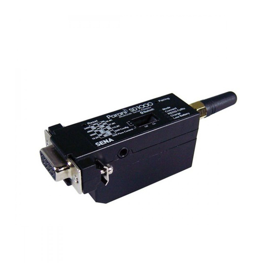
The working distance of Parani-SD1000 with default antenna is 100m Parani-SD1000 has a compact design, which allows it to be placed conveniently into various devices or equipment. Its detachable antenna has the ability to optimize the quality and distance of wireless communications. -
Page 9: Product Specification
1.3. Product Specification Parani-SD1000 One female DB9 serial port for data communication Serial Interface Serial UART speed up to 921.6kbps CTS/RTS flow control, DTR/DSR for loop-back & full transfer Bluetooth v2.0 + EDR Bluetooth Interface Profile: Serial Port Profile Class 1... - Page 10 Operating temperature: -20 ~ 70 Environmental Storage temperature: -40 ~ 85 Humidity : 90% (Non-condensing) - Dimension (L x W x H) Physical properties 74 x 31 x 16 (mm) (No battery pack) 74 x 31 x 19.5 (mm) (with standard battery pack) 74 x 31 x 31.4 (mm) (with extended battery pack) - Weight 24g (No battery pack)
-
Page 11: Getting Started
Parani-SD1000 can be powered from either external DC power adaptor/external power source, or by optional battery pack. To power the SD1000 from the external DC power adaptor or external power source, connect the power jack to the power connector of the Parani-SD1000 using the DC power... -
Page 12: Connecting Device To Parani-Sd1000
The Parani-SD1000 also supports optional standard battery pack (240mAh) and extended battery pack (900mAh). Attach the battery pack to the Parani-SD1000 as shown below to power the SD1000 using the battery pack. To recharge the battery pack, connect the external DC power adaptor as... -
Page 13: How To Attach Battery Pack To Parani-Sd1000
Figure 2-4 Attaching Battery Pack to Parani-SD1000 2.2.4. How to attach battery pack to Parani-SD1000 Step 1 : Remove two screws of SD1000 at the bottom and remove the cover. Figure 2-5 Remove Parani-SD1000 bottom cover... - Page 14 Step 2 : Slide the battery pack into the Parani-SD1000 slot. Figure 2-6 Attach the battery pack Step 3 : Fasten the battery pack to the Parani-SD1000. Figure 2-7 Fasten the battery pack...
-
Page 15: Configuration
SD1000 has connected last. When Parani-SD1000 is initially used or after hardware reset, there is no BD address stored in Parani-SD1000. In this case, Mode1 will not be able to work properly. The mode change to Mode1 can be made after Parani-SD1000 succeeds to connect to one other Bluetooth device. -
Page 16: Led Indicators
3.4. Data Bit Parani-SD1000 supports only 8 data bit. In the case of 7 data bit and even/odd parity, use SD 8 data bit and none parity. At this time, master and slave are Parani-SD, Parani-ESD or Parani-MSP series. -
Page 17: Hardware Flow Control
When hardware flow control is not being used, the Parani-SD1000 clears the buffer to secure room for the next data when the buffer becomes full. This can mean a loss of data may occur. As the transmission data becomes large, the possibility of data loss becomes greater. -
Page 18: Pairing Button
Handshaking * Note: You cannot set the Parani-SD1000 to a Baud rate of 1200 and 230K by way of the Dipswitch. If you want to use them, to set these speeds, please configure the dipswitch to S/W Config setting and use ParaniWIN or AT commands. -
Page 19: Software And Utility
Run ParaniWIN. Figure 3-2 Serial Port Setting Set each option properly and click [Confirm]. If the settings of the Parani-SD1000 are different from the ParaniWin, an error message will pop up. If the Parani-SD1000 is in the status of connection, warning message will pop up. - Page 20 Figure 3-3 Main Window Figure 3-4 Information Window Serial port settings can be changed by <Start Configuration> and <ParaniWIN Configuration> of ParaniWIN in the menu bar at upper left corner of the window without re-running the ParaniWIN program.
- Page 21 Figure 3-5 Menu Bar at Upper Left corner of ParaniWIN When the ParaniWin software is able to access the Parani-SD1000 properly, the icons in the left side window come will become available for use. In device configuration window, hardware reset can be executed or operation mode and RS232 can be configured as well.
- Page 22 Command response to ON or OFF. For Parani-SD1000, hardware flow control can be configured only by dip switch. And parity, stop bit can be configured only SW config mode. Thus H/W Flow Control option will not work in this case.
- Page 23 The signal strength test shows LInkQuality and RSSI values. The closer LinkQuality is to 255 and RSSI is to 0, this means the Parani-SD1000 has a good connection to the connected Bluetooth device. In general, the wireless connectivity is at its best within 10 meters. You can push the STOP button at anytime in order to terminate the signal strength test.
-
Page 24: Paraniupdater
SD1000 at http://www.sena.com. With the ParaniUpdater, you can update the firmware of Parani- SD1000 by selecting the firmware image file and pushing Start button. * Note: DO NOT power off Parani-SD1000 while the firmware update is progressing, this may damage the Parani-SD1000. -
Page 25: Terminal Program
This manual will explain the method using HyperTerminal. If you need to install HyperTerminal, click start>setting>control panel>add/remove programs. For more precise details on HyperTerminal installations, please refer to Microsoft Windows Help section. Figure 3-12 HyperTerminal Attach Parani-SD1000 to serial port of host computer and power on the Parani-SD1000. Check Mode LED. (See 3.2) - Page 26 Make sure that the Connect LED is turned off and the Stanby LED is turned on before attempting to send any kind of AT commands to the Parani-SD1000. Then launch HyperTerminal, it can usually be found in start >programs >accessories >communication >HyperTerminal. Select the Serial port that Parani-SD1000 is connected to.
-
Page 27: Multiple Connection Mode
4. Multiple Connection Mode 4.1. Overview Parani-SD1000 supports multiple connections up to 4 slave units. There are two types of multiple connection modes: Multi-Drop Mode and Node Switching Mode. Figure 4-1 Multi-Drop Mode In Multi-Drop Mode a master unit can connect to maximum 4 slave units at the same time and they transfer data bi-directionally as in Figure 4-1. -
Page 28: Configuration
4.2. Configuration All the slaves should be in the status of waiting for connection either in Mode 2 or Mode 3 and the master unit tries to connect to the slave units. The master unit needs to be configured to work in a multiple connection mode using AT+MULTI,x command, which makes master reboots after execution. -
Page 29: At Commands
4.3. AT Commands 4.3.1. AT+MULTI,n Select a multiple connection mode. Refer to Table 4-1 for descriptions. 4.3.2. AT+MLIST? It shows the current mode, the connection status and the BD addresses of slaves. at+mlist? CURRENT MODE: MULTI DROP TASK1 – 000195000001 TASK2 –... -
Page 30: Notes
4.4. Notes When large data exchange occurs in Multi-drop mode without flow-control enabled, the master unit may experience data loss. It may also experience occasional disconnections and/or system rebooting especially when bi-directional communication happens. It is strongly recommended to perform extensive performance test before any real world field applications. -
Page 31: Approval Information
EN 62311: 2008 ETSI EN 301 489-1 V1.6.1 ETSI EN 301 489-17 V1.2.1 ETSI EN 300 328 V1.6.1 5.3. MIC Type Registration Certification No: SNA-Parani-SD1000 5.4. TELEC Type Registration Certification No: 010WWBT0002 5.5. SIG Specification Version: 2.0/2.0 + EDR QDID: B014291 5.6. -
Page 32: Rf Information
GFSK (Gaussian-filtered Frequency Shift Keying) Pi/4 DQPSK (pi/4 rotated Differential Quaternary Phase Shift Keying) 8DPSK (8 phase Differential Phase Shift Keying) 6.5. Radio Output Power Products Radio Output Power Parani-SD1000 +18dBm 6.6. Receiving Sensitivity Products Radio Output Power Parani-SD1000 -88dBm 6.7. -
Page 33: Appendix A: Connections
Appendix A: Connections A.1. Serial Port Pin Outs Parani-SD is a DCE device compatible with the RS232 standard, a DB9 female interface. Figure A-1 Pin layout of the DB-9 female connector Table A-1. Pin assignment of the DB-9 female connector Pin # Signal Direction... -
Page 34: Serial Wiring Diagram
A.2. Serial Wiring Diagram A.2.1. To Host with DTE Interface A.2.2. To Host with DCE Interface... -
Page 35: Appendix B: At Commands
Appendix B: AT Commands B.1. Terminology B.1.1. AT Command AT command set is the i n fact standard l anguage for controlling m odems . The AT command set was developed by H ayes and is recognized by virtually all p ersonal computer modems. -
Page 36: Symbols
B.1.6. Symbols The symbols are used for the description of command syntax as follows: Symbols Meaning ASCII Code Carriage return 0x0D Line feed 0x0A Carriage return + Line feed 112233445566 Bluetooth device address N or m One digit decimal number Timeout in seconds B.2. -
Page 37: Command Description
B.3. Command Description B.3.1. ATZ OK Response Software Reset Purpose This has the same effects as Powercycling the unit. Description This command disconnects any connected Bluetooth device, and stops ongoing tasks. After rebooting, the status will be decided by the preset operation mode. Some AT commands require the ATZ command be run so that the commands can take effect. -
Page 38: At+Btinfo
Parani-SD, v2.0.0 for the version of firmware, and 445566 for the last 6 digits of BD address. Mode=MODE0/MODE1/MODE2/MODE3 Status=STANDBY/PENDING/CONNECT Auth=0/1 (Authentication is not activated when 0) Encrypt=0/1 (Encryption is not activated when 0) FlowControl=HWFC/NoFC 000B530011FF,SENA,MODE0,PENDING,1,1,HWFC Example B.3.7. AT+BTINQ? 112233445566,FriendlyName,CoD Response 112233445566,FriendlyName,CoD 112233445566,FriendlyName,CoD... -
Page 39: At+Btmode,N
CURRENT MODE: MULTI-DROP MODE TASK1 – 000195000001 TASK2 – DISCONNECT TASK3 – DISCONNECT TASK4 – 000195000004 B.3.11. AT+BTMODE,n OK Response Set operation mode Purpose n=0: MODE0 (Default) Parameters n=1: MODE1 n=2: MODE2 n=3: MODE3 When the operation status is ‘Pending’ currently, change the status to ‘Standby’ with Description AT+BTCANCEL prior to this command. -
Page 40: Ato (Atox, Atobdaddr)
AT+SETESC,42 Example B.3.15. ATO (ATOx, ATObdaddr) None Response Convert the operation status of ‘Standby’ to ‘Connect’ Purpose You can convert the operation status of ‘Standby’ to ‘Connect’ ready to transmit data. In Description Node Switching mode, a specific slave can be specified to become an active connection by specifying the connection number or the Bluetooth address. -
Page 41: At+Btscan112233445566,To
AT+BTSCAN,2,30 Example B.3.19. AT+BTSCAN112233445566,to OK Response CONNECT 112233445566 OK ERROR Wait for connection by a Bluetooth device with a given BD address Purpose 112233445566=BD address Parameters to= time duration in seconds Parani-SD will wait to be connected to by the Bluetooth device with the given BD address. Description If the parameter of to is 0, it will wait forever. -
Page 42: At+Btkey=$String
The current Bluetooth connection will be disconnected. It takes about Supervision Description Timeout(S37) to detect an abnormal disconnection such as power off and moving out of service range. In multiple connection modes, a specific connection can be specified to be disconnected by specifying the connection number or the Bluetooth address The response message of ‘DISCONNECT’... -
Page 43: At+Btname=$String
Set authentication and data encryption Purpose Authentication=0: Inactivate (Default) Parameters Authentication=1: Activate Encryption=0: Inactivate (Default) Encryption=1: Activate If the authentication is activated, the pin code must be set by AT+BTKEY command. Data Description encryption cannot be used when authentication is not enabled, i.e. Authentication=0 and Encryption=1 will not work properly. -
Page 44: Atsnn
All parameters are stored at S-register in flash memory. These values are sustained until Description hardware reset. B.3.32. ATSnn? value Response OK Display a given S-register Purpose nn= Address of S-register Parameters A specific S-register will be displayed. Description B.3.33. - Page 45 AT+BTSEC,Auth,Encr ◎ AT+BTLAST? ○ ○ AT+BTMODEn ◎ AT+BTNAME=”Name” ◎ AT+BTKEY=”nnnn” ◎ AT+BTINFO? ○ AT+BTLPM,n ◎ AT+BTSD? ○ ○ AT+BTCSD ◎ AT+BTFP,n ◎ AT+UARTCONFIG,b,p,s ◎ AT+USEDIP? ○ ○ AT+BTVER? ○ ○ AT+BTRSSI,n ● ◎ Valid only when Parani-SD is not connected to other Bluetooth device. ●...
-
Page 46: Appendix C: S-Register
Appendix C: S-Register S-registers contain 52 parameters for the Parani-SD Series. These are stored in flash memory and the values will be saved unless hardware reset is executed. The value of S-register can be accessed and changed with ATS command. Some S-registers not shown below are set to maximize the performance of Parani-SD Series. -
Page 47: S12: Clear Data Buffer When Disconnected (Default 1)
S11=1, Parani-SD allows for the escape sequence character. Whenever it is needed, the Connect status can be changed to Standby. C.7. S12: Clear Data Buffer When Disconnected (default 1) S12=0, Parani-SD does not clear the data buffer received from host system when disconnected. S12=1, Parani-SD clears the data buffer when disconnected. -
Page 48: S28: Escape Sequence Character (Default 43)
Intercharacter Timeout * Optimal Value(S23 x S26) 50ms 100ms 200ms * When 10 bytes data are sent every intercharacter timeout, they are sent separately by 10 bytes at the optimal value. If the intercharater timeout is set below the optimal value, the date will be put together and sent by 20, 30, 40 bytes or more. -
Page 49: S48: Low Power Max Interval (Default 5000)
C.23. S48: Low Power Max Interval (default 5000) This is the max interval value to use low power mode, which is set to 5000 initially. (5000 x 625μsec = 3125msec) C.24. S49: Low Power Min Interval (default 4500) This is the min interval value to use low power mode, which is set to 4500 initially. (4500 x 625μsec = 2812msec) A small interval increases power consumption, a large interval increases latency. -
Page 50: S59: Current Slave In Communication (Default 0)
C.31. S59: Current Slave in Communication (default 0) This value shows the current slave number in communication. The value is automatically stored when the slave is selected for communication. This value can also be set by user so the master unit connects to a specific slave to connect first in case the master unit reboots. -
Page 51: Appendix D: Trouble Shooting
Appendix D: Trouble Shooting D.1. No Data Transmission D.1.1. COM Port Settings Check whether the Baud rate of Parani-SD matches that of its host equipment. Check whether the host equipment has a Data bit setting of 8. Parani-SD supports only 8 Data bit settings. -
Page 52: Appendix E: Parani-Sd1000 Mechanical Drawing
Appendix E: Parani-SD1000 mechanical drawing E.1. Parani-SD1000 mechanical drawing (mm) 101 with stub antenna 74 without antenna... -
Page 53: Battery Pack Mechanical Drawing (Mm)
E.2. Battery pack mechanical drawing (mm) Standard Battery Pack Extended Battery Pack... -
Page 54: Appendix F: Warranty
(a) any misapplication or misuse of the Product; (b) failure of Customer to adhere to any of SENA’s specifications or instructions; (c) neglect of, abuse of, or accident to, the Product; or (d) any associated or complementary equipment or software not furnished by SENA. -
Page 55: Software Product Warranty Details
- Replacement of parts due to normal wear and tear, - Hardware has been altered in any way, - Product that has been exposed to repair attempts by a third party without SENA’s written consent, - Hardware hosting modified SENA Software, or non-SENA Software, unless modifications have been approved by SENA.
Need help?
Do you have a question about the PARANI-SD1000 and is the answer not in the manual?
Questions and answers