Table of Contents
Advertisement
Advertisement
Table of Contents

Related Manuals for Sena Parani-SD100


Summary of Contents for Sena Parani-SD100
-
Page 1: User Guide
Parani-SD100/200 User Guide Version 1.1.6 2009-03-10... - Page 2 This device is not approved for life-support or medical systems. Changes or modifications to this device not explicitly approved by Sena Technologies will void the user's authority to operate this device.
-
Page 3: Revision History
Revision History Revision Date Name Description V1.1.2 2007-05-26 Yh Moon Initial Revision History V1.1.3 2007-09-12 Yh Moon Update Approval, Command Validity, 3.4 data bit, A.1 voltage, B3.7, remove at+dfu, S23, B3.4, ParaniWIN Dip switch conf. V1.1.4 2007-01-07 Yh Moon Firmware v1.1.3 update reflected V1.1.5 2009-01-21 WJ Kim... -
Page 4: Table Of Contents
Contents 1. Introduction 1.1. Overview..........................7 1.2. Package Check List ......................7 1.2.1. Single Unit Package ....................7 1.2.2. Bulk-Pack Package .....................7 1.3. Product Specification......................7 2. Getting Started 2.1. Panel Layout........................10 2.2. Connecting the Hardware....................11 2.2.1. Connecting Power to Parani-SD ................11 2.2.2. - Page 5 B.1.3. Operation Mode ......................29 B.1.4. Operation Status ....................... 29 B.1.5. Security ........................29 B.1.6. Symbols ........................30 B.2. Command Category......................30 B.3. Command Description ......................31 B.3.1. ATZ......................... 31 B.3.2. AT&F ........................31 B.3.3. AT........................... 31 B.3.4. AT+UARTCONFIG,Baudrate,Parity,Stopbit.............. 31 B.3.5.
- Page 6 D.3.1. RF Processing Delay ....................45 D.3.2. RF Transmission Environment .................. 45 Appendix E: Parani-SD100/200 mechanical drawing E.1. Parani-SD100 mechanical drawing ..................46 E.2. Parani-SD200 mechanical drawing ..................47 E.3. Parani-SD200 battery pack mechanical drawing ..............48 Appendix F: Warranty F.1.
-
Page 7: Introduction
Bluetooth devices; user may connect other Bluetooth devices that support the Serial Port Profile. Parani-SD provides several models with different communication ranges, from 30m (Parani-SD200) up to 100m (Parani-SD100) for various applications. Parani-SD has a compact design, which allows it to be placed conveniently into various devices or equipment. - Page 8 Standby Connect Serial Rx/Tx Power Supply voltage: 5V ~ 12V DC Supply current Parani-SD100 : minimum 300mA Parani-SD200 : minimum 150mA Nominal power consumption Parani-SD100 : 60mA@9600bps, 81mA@115Kbps Parani-SD200 : 58mA@9600bps, 66mA@115Kbps Common Power supply options: Power via a standard AC-plug DC-adapter...
- Page 9 Note Bluetooth v1.2 supports improved AFH function. AFH function is to mitigate the interference between WiFi and Bluetooth radios by automatically avoiding the active WiFi channel from Bluetooth link. However, AFH does not provide a complete solution making WiFi and Bluetooth work together in harmony.
-
Page 10: Getting Started
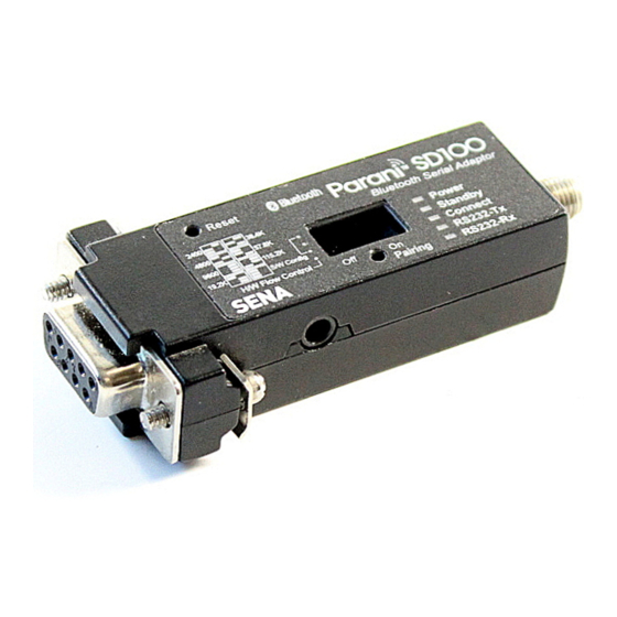
- Terminal emulation program running on the PC - One battery pack and two ‘ AA’batteries (optional accessory for Parani-SD200 only) 2.1. Panel Layout This section describes the panel layout of the Parani-SD. Figure 2-1 The panel layout of Parani-SD100... -
Page 11: Connecting The Hardware
Figure 2-2 The panel layout of Parani-SD200 2.2. Connecting the Hardware This section describes how to connect the Parani-SD Series to the serial device. - Connect a power source to the Parani-SD Series. - Connect the Parani-SD Series to a serial device. 2.2.1. -
Page 12: Connecting Device To Parani-Sd
2.2.2. Connecting Device to Parani-SD Connect the serial device to the Parani-SD Series as shown below. Figure 2-4 Connecting a Serial Device to Parani -SD 2.2.3. Attaching Batter Pack to Parani-SD200 The Parani-SD200 supports a battery pack that can carry two AA batteries as an optional accessory. Users can use either standard or rechargeable batteries. -
Page 13: Configuration
3. Configuration 3.1. Operation Modes In addition to the serial port configurations, the Parani-SD requires also includes some settings for Bluetooth. For getting the most out of Parani-SD, user should understand the following Bluetooth connection schemes. A Bluetooth device can play a role as a master or slave. Master tries to connect itself to other Bluetooth devices, and slave is waiting to be connected from other Bluetooth devices. -
Page 14: Serial Ports
Table 3-2 The Parani-SD LED Indicators Indicator Power LED Standby LED Connect LED Mode0 ┏━━━━━ ┏━━━━━ Green Mode1 ┏━━━━━ Green (every 1 sec) ┏┓ Green Mode2 ┏━━━━━ Green (every 3 sec) ┏┰┓ Green ┏━━━━━ Green (every 3 sec) ┏┰┓ Mode3 Green ┏━━━━━... -
Page 15: Reset To Factory Defaults
3.6 Reset to Factory Defaults To set all the configuration settings to its factory default parameters, press the reset button, depicted in Fig. 1-3. Press and hold (for at least 1 sec) the reset button with a narrow pointed tool like paper clip. Reset works only when power is on. - Page 16 Step 3. Press the Pairing Button of SD2 for 2 seconds until Standby LED turns off and Connect LED blinks 3 times every 2 seconds. Now press again the Pairing Button for 2 seconds until Connect LED blinks every 0.5 second. Step 4.
-
Page 17: Software And Utility
3.9 Software and Utility This configuration software and utility for firmware update is included with the product, which also can be downloaded from http://www.sena.com Table 3-8 Configuration Software Software Purpose Operating System ParaniWIN Configuration MS Windows 98SE or Higher ParaniUpdater... - Page 18 Figure 3-3 Main Window Figure 3-4 Information Window...
- Page 19 Serial port settings can be changed by <Start Configuration> and <ParaniWIN Configuration> of ParaniWIN in the menu bar at upper left corner of the window without re-running the ParaniWIN program. Figure 3-5 Menu Bar at Upper Left corner of ParaniWIN When the ParaniWin software is able to access the Parani-SD properly, the icons in the left side window come will become available for use.
- Page 20 Command response to ON or OFF. For Parani-SD100/200, hardware flow control can be configured only by dip switch. And parity, stop bit can be configured only SW config mode. Thus H/W Flow Control option will not work in this case.
- Page 21 Figure 3-8 Signal Strength Test The signal strength test shows LInkQuality and RSSI values. The closer LinkQuality is to 255 and RSSI is to 0, this means the Parani-SD has a good connection to the connected Bluetooth device. In general, the wireless connectivity is at its best within 10 meters. You can push the STOP button at anytime in order to terminate the signal strength test.
- Page 22 Figure 3-9 Connection(in) Window If the Connection Wizard icon is clicked, an easy to use pairing menu will appear: Figure 3-10 Connection Wizard Window...
-
Page 23: Paraniupdater
3.11 ParaniUpdater Parani-SD supports firmware updates. You can download new firmware images for the Parani-SD at http://www.sena.com. With the ParaniUpdater, you can update the firmware of Parani-SD by selecting the firmware image file and pushing Start button. * Note: DO NOT power off Parani-SD while the firmware update is progressing, this may damage the Parani-SD. - Page 24 Figure 3-12 HyperTerminal Attach Parani-SD to serial port of host computer and power on the Parani-SD. Check Connect LED and Standby LED Their status may be as follows: Table 3-9 Connect LED and Standby LED status Connect LED Standby LED Meanings Connected to somewhere Blinking...
-
Page 25: Approval Information
4. Approval Information 4.1. FCC 4.1.1. FCC Compliance Statement This device complies with part 15 of the FCC Rules. Operation is subject to the following two conditions: (1) This device may not cause harmful interference, and (2) This device must accept any interference received, Including interference that may cause undesired operation 4.1.2. -
Page 26: Rf Information
5.2. Number of Frequency Channel 79 channels 5.3. Transmission Method FHSS(Frequency Hopping Spread Spectrum) 5.4. Modulation Method GFSK(Gaussian-filtered Frequency Shift Keying) 5.5. Radio Output Power Products Radio Output Power Parani-SD100 +18dBm Parani-SD200 +4dBm 5.6. Receiving Sensitivity Products Radio Output Power Parani-SD100 -88dBm... -
Page 27: Appendix A: Connections
Appendix A: Connections A.1. Serial Port Pin Outs Parani-SD is a DCE device compatible with the RS232 standard, a DB9 female interface. Figure A-1 Pin layout of the DB-9 female connector Table A-1. Pin assignment of the DB-9 female connector Pin # Signal Direction... -
Page 28: Serial Wiring Diagram
A.2. Serial Wiring Diagram A.2.1. To Host with DTE Interface A.2.2. To Host with DCE Interface... -
Page 29: Appendix B: At Commands
Appendix B: AT Commands B.1. Terminology B.1.1. AT Command AT command set is the in fact standard language for controlling modems . The AT command set was developed by Hayes and is recognized by virtually all personal computer modems. Parani-SD provides the extended AT command set to control and configure the serial parameters and Bluetooth connection. -
Page 30: Symbols
B.1.6. Symbols The symbols are used for the description of command syntax as follows: Symbols Meaning ASCII Code Carriage return 0x0D Line feed 0x0A Carriage return + Line feed 112233445566 Bluetooth device address N or m One digit decimal number Timeout in seconds B.2. -
Page 31: Command Description
B.3. Command Description B.3.1. ATZ OK Response Purpose Software Reset Description This has the same effects as Powercycling the unit. This command disconnects any connected Bluetooth device, and stops ongoing tasks. After rebooting, the status will be decided by the preset operation mode. Some AT commands require the ATZ command be run so that the commands can take effect. -
Page 32: At+Usedip
B.3.5. AT+USEDIP? m Response Purpose Check the Baud rate set by the dip switch Description m=0: Dip switches are set to ‘ S/W Config’ m=1: Please view the dipswitches to view your baud rate. Reference AT, ATZ, AT&F, ATS B.3.6. -
Page 33: At+Btver
B.3.9. AT+BTVER? SD100v1.1.3 Response OK Purpose Display device firmware version Description Display device firmware version Reference AT+BTINFO? B.3.10. AT+BTMODE,n OK Response Purpose Set operation mode Parameters n=0: MODE0 (Default) n=1: MODE1 n=2: MODE2 n=3: MODE3 Description When the operation status is ‘ Pending’currently, change the status to ‘ Standby’with AT+BTCANCEL prior to this command. -
Page 34: Ato
Reference +++, ATO Example AT+SETESC,42 B.3.13. ATO Response None Purpose Convert the operation status of ‘ Standby’to ‘ Connect’ Description You can convert the operation status of ‘ Standby’to ‘ Connect’ready to transmit data. Reference +++, AT+SETESC B.3.14. AT+BTCANCEL OK Response Purpose Terminate the current task... -
Page 35: At+Btscan112233445566,To
Description For the given to, Parani-SD is waiting for the inquiry and connection from other Bluetooth devices. If the parameter of to is 0, it will wait forever. When connection is made with other Bluetooth device, response will be ‘ CONNECT’with its BD address. -
Page 36: Ata
Description Parani-SD attempts to connect to the Bluetooth device with the given BD address. To make successful connection, the Bluetooth device must be in Page scan mode. This attempt continues for 5 minutes. If it fails to make connection, response is ‘ ERROR ’ . Reference AT+BTINQ?, AT+BTSCAN Example... -
Page 37: At+Btsd
Description Pin code is a string, which allows up to 16 alpha-numeric characters. Based on this pin code, Parani-SD generates a link key which is used in actual authentication process Reference AT+BTCSD, AT+BTFP, AT+BTSD?, AT+BTSEC, ATZ, AT&F Example AT+BTKEY=”apple” B.3.24. AT+BTSD? ... -
Page 38: At+Btname=$String
Description If the authentication is activated, the pin code must be set by AT+BTKEY command. Data encryption cannot be used when authentication is not enabled, i.e. Authentication=0 and Encryption=1 will not work properly. Reference AT+BTCSD, AT+BTFP, AT+BTSD?, AT+BTSD?, ATZ, AT&F B.3.28. -
Page 39: At&V
B.3.31. AT&V S0:m0;S1:m1; …Sn:mn Response OK Purpose Display all the S-registers Description All parameters are stored at S-register in flash memory. These values are sustained until a hardware reset. Reference B.3.32. ATSnn? value Response OK Purpose Display a given S-register Parameters... - Page 40 ◎ ATA112233445566 ◎ ◎ ◎ AT+BTSCAN ◎ AT+BTSCAN,n,to ◎ AT+BTSCAN112233445566,to ○ AT+BTCANCEL ○ AT+SETESC ◎ ● ● ◎ AT+BTSEC,Auth,Encr ○ ○ AT+BTLAST? ◎ AT+BTMODEn ◎ AT+BTNAME=”Name” ◎ AT+BTKEY=”nnnn” AT+BTINFO? ○ ◎ AT+BTLPM,n ○ ○ AT+BTSD? ◎ AT+BTCSD ◎ AT+BTFP,n ◎ AT+UARTCONFIG,b,p,s AT+USEDIP? ○...
-
Page 41: Appendix C: S-Register
Appendix C: S-Register S-registers contains 52 parameters for the Parani-SD Series. These are stored in flash memory and the values will be saved unless hardware reset is executed. The value of S-register can be accessed and changed with ATS command. Some S-registers not shown below are set to maximize the performance of Parani-SD Series. -
Page 42: S12: Clear Data Buffer When Disconnected (Default 0)
C.7. S12: Clear Data Buffer When Disconnected (default 0) S12=0, Parani-SD does not clear the data buffer when disconnected. S12=1, Parani-SD clears the data buffer when disconnected. C.8. S13: Enable DCD Signal (default 1) S13=0, DCD signal off S13=1, DCD signal on C.9. -
Page 43: S28: Escape Sequence Character (Default 43)
* When 10 bytes data are sent every intercharacter timeout, they are sent separately by 10 bytes at the optimal value. If the intercharater timeout is set below the optimal value, the date will be put together and sent by 20, 30, 40 bytes or more. C.15. -
Page 44: S48: Low Power Max Interval (Default 2048)
C.24. S48: Low Power Max Interval (default 2048) This is the max interval value to use low power mode, which is set to 2048 initially. (2048 x 625μsec = 1280msec) C.25. S49: Low Power Min Interval (default 800) This is the min interval value to use low power mode, which is set to 800 initially. (800 x 625μsec = 500msec) When sniff mode, a small sniff interval increases power consumption, a large sniff interval increases latency. -
Page 45: Appendix D: Trouble Shooting
Appendix D: Trouble Shooting D.1. No Data Transmission D.1.1. COM Port Settings Check whether the Baud rate of Parani-SD matches that of its host equipment. Check whether the host equipment has a Data bit setting of 8. Parani-SD supports only 8 Data bit settings. -
Page 46: Appendix E: Parani-Sd100/200 Mechanical Drawing
Appendix E: Parani-SD100/200 mechanical drawing E.1. Parani-SD100 mechanical drawing 95.3 with stub antenna 70.0 without antenna 16.2 20.5 30.8... -
Page 47: Parani-Sd200 Mechanical Drawing
E.2. Parani-SD200 mechanical drawing 100.8 with stub antenna 75.3 without antenna 16.2 20.5 30.8... -
Page 48: Parani-Sd200 Battery Pack Mechanical Drawing
E.3. Parani-SD200 battery pack mechanical drawing 68.4 21.0... -
Page 49: Appendix F: Warranty
(a) any misapplication or misuse of the Product; (b) failure of Customer to adhere to any of SENA’ s specifications or instructions; (c) neglect of, abuse of, or accident to, the Product; or (d) any associated or complementary equipment or software not furnished by SENA. -
Page 50: Software Product Warranty Details
- Replacement of parts due to normal wear and tear, - Hardware has been altered in any way, - Product that has been exposed to repair attempts by a third party without SENA’ s written consent, - Hardware hosting modified SENA Software, or non-SENA Software, unless modifications have been approved by SENA.
Need help?
Do you have a question about the Parani-SD100 and is the answer not in the manual?
Questions and answers