
Subscribe to Our Youtube Channel
Related Manuals for Rock Shox reverb a2


Summary of Contents for Rock Shox reverb a2
- Page 1 Reverb™ & s e r v i c e m a n u a l GEN.0000000005342 Rev A © 2017 SRAM, LLC...
- Page 2 SRAM LLC WARRANTY ® EXTENT OF LIMITED WARRANTY Except as otherwise set forth herein, SRAM warrants its products to be free from defects in materials or workmanship for a period of two years after original purchase. This warranty only applies to the original owner and is not transferable. Claims under this warranty must be made through the retailer where the bicycle or the SRAM component was purchased.
- Page 3 SAFETY FIRST! We care about YOU. Please, always wear your safety glasses and protective gloves when servicing RockShox® products. Protect yourself! Wear your safety gear!
-
Page 4: Table Of Contents
TABLE OF CONTENTS PRODUCT IDENTIFICATION - REVERB™ ........................................6 RECOMMENDED SERVICE INTERVALS ........................................7 SERVICE HISTORY ................................................7 BRASS KEY SIZE ................................................7 TORQUE VALUES ................................................8 PARTS, TOOLS, AND SUPPLIES ..........................................9 EXPLODED VIEW - ASSEMBLY ..................................10 EXPLODED VIEW - COMPONENT ..................................11 SEATPOST SERVICE ......................................12 SEATPOST REMOVAL .............................................. - Page 5 R o c k S h o x ® S e r v i c e We recommend that you have your RockShox suspension serviced by a qualified bicycle mechanic. Servicing RockShox suspension requires knowledge of suspension components, as well as the use of specialized tools and lubricants/fluids. Failure to follow the procedures outlined in this service manual may cause damage to your component and void the warranty.
-
Page 6: Product Identification - Reverb
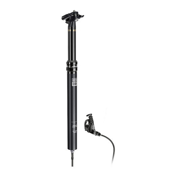
P r o d u c t I d e n t i f i c a t i o n - R e v e r b ™ Production versions of Reverb can be identified visually. Your Reverb can be A2 - Upper Post - No RockShox®... -
Page 7: Recommended Service Intervals
Extends wiper seal, top cap bushing, and brass key lifespan Perform remote lever bleed Ensures proper remote actuation function Replace all parts included in the Reverb A2 Service Restores hydraulic system and function Kit - 200 hours Every 200 Hours... -
Page 8: Torque Values
T o r q u e V a l u e s Part Tool Torque Internal seal head 28 N•m (250 in-lb) 23 mm open end wrench Top cap assembly 27-29 N•m (238-256 in-lb) 34 mm open end wrench Air valve base plate 3.9-5.1 N•m (35-45 in-lb) 26 mm open end wrench Post hose barb... -
Page 9: Parts, Tools, And Supplies
• Bicycle work stand • Reverb B1 Service Kit - 400 Hour • Park Tool® AV-5 vise inserts • Reverb A2 Service Kit - 200 Hour • Schrader valve core tool • Reverb brass keys, quantity 3 (use correct size) •... -
Page 10: Exploded View - Assembly
E x p l o d e d V i e w - A s s e m b l y Inner Shaft Assembly Internal Floating Piston Assembly Poppet Valve Assembly Saddle Clamp Assembly Bleed Screw Remote Lever Remote Lever Hose Barb Actuator Post Head... -
Page 11: Exploded View - Component
E x p l o d e d V i e w - C o m p o n e n t Inner Shaft Assembly Remote Lever Internal Floating Piston Assembly Actuator Remote Lever Hose Barb Poppet Valve Assembly Hydraulic Hose Saddle Clamp Assembly Top Cap Assembly Poppet Cover Retaining Ring... -
Page 12: Seatpost Service
S e a t p o s t S e r v i c e S e a t p o s t R e m o v a l Secure the bicycle in an upright position. NOTI CE The Reverb™ seatpost will be removed from the bicycle. Do not clamp the Reverb seatpost in a bicycle work stand before removal. - Page 13 Remove the remote lever assembly from the bicycle handlebar. Wrap a shop towel around the upper post and hose barb. The shop towel will absorb any Reverb™ hydraulic fluid that may drip. Unthread and remove the hose barb and hose. Hydraulic fluid may drip from the hose barb.
-
Page 14: 50/200/400 Hour Service
5 0 / 2 0 0 / 4 0 0 H o u r S e r v i c e L o w e r P o s t R e m o v a l N OTIC E Use bench vise soft jaw inserts to prevent damage to the seatpost or any seatpost components when clamping it into a vise. - Page 15 A2: Remove the retaining ring from the lower post. Retaining Ring Pliers B1: Lift the scalloped end of the retaining ring and remove the retaining ring from the post. Pick Slide the lower post down to expose the air valve base plate. Remove the seatpost from the vise.
- Page 16 Spray the inner shaft and RockShox® Vise Blocks with isopropyl alcohol 26 mm and wipe them with a clean shop towel. The clamping surfaces must be free of oil and grease. Clamp the inner shaft into the 10 mm slot in the vise blocks. RockShox Vise Blocks Unthread and remove the air valve base plate from the inner shaft.
- Page 17 Slide the lower post assembly up and remove it from the upper post. Remove the foam ring and bottomout o-ring. Clean the inside and outside of the lower post with isopropyl alcohol and a shop towel, then set it aside. 50 Hour Service Set the foam ring and o-ring aside on a clean shop towel.
- Page 18 Remove the three brass keys from the upper post. page 7, record the number of lines, which indicate key size, marked on the brass keys for future reference. The brass keys should be replaced with new brass keys of the same size, if worn, during each service interval.
-
Page 19: 200 (B1) Hour Service
2 0 0 ( B 1 ) H o u r S e r v i c e T o p C a p a n d S e a l H e a d B u s h i n g R e p l a c e m e n t The following steps are to be completed during the B1 200 hour service interval and include replacing parts included in the Reverb™... - Page 20 Apply a liberal amount of SRAM® Butter grease around the inside of a new top cap assembly and onto the seals. Install the new top cap assembly, wiper seal end first, over the seal head and onto the upper post assembly. Slide the top cap assembly down until it is positioned below the upper post key slots.
-
Page 21: 200 (A2) & 400 (B1) Hour Service
Install a new o-ring and bushing onto the seal head. Pinch the bushing to secure it around the seal head. To continue the 200 (B1) Hour Service , proceed to Brass Keys Installation. Top Cap and Seal Head Bushing Replacement... -
Page 22: Inner Shaft And Seal Head Removal
2 0 0 ( A 2 ) & 4 0 0 ( B 1 ) H o u r S e r v i c e I n n e r S h a f t a n d S e a l H e a d R e m o v a l ⚠... - Page 23 Remove the upper post from the vise and pour the hydraulic fluid into an oil pan or container. Inner Shaft and Seal Head Removal...
-
Page 24: Poppet Valve Removal
2 0 0 ( A 2 ) & 4 0 0 ( B 1 ) H o u r S e r v i c e P o p p e t V a l v e R e m o v a l Clamp the upper post into a bench vise and Park Tool®... - Page 25 Remove the poppet valve from the housing and inner shaft. Set the poppet valve aside. Needle Nose Pliers Poppet Valve Removal...
-
Page 26: Upper Post Disassembly
2 0 0 ( A 2 ) & 4 0 0 ( B 1 ) H o u r S e r v i c e U p p e r P o s t D i s a s s e m b l y Clamp the upper post head into the vise with flat soft jaws. - Page 27 Remove the internal floating piston (IFP) from the upper post. Insert seven to nine plastic cable ties (cable tie size may vary), one at a time, into the upper post and through the center of the IFP. Pull the cable ties out of the upper post and remove the IFP. Discard the IFP.
-
Page 28: Top Cap Installation
2 0 0 ( A 2 ) & 4 0 0 ( B 1 ) H o u r S e r v i c e T o p C a p I n s t a l l a t i o n Apply a liberal amount of SRAM®... -
Page 29: Inner Shaft Assembly
2 0 0 ( A 2 ) & 4 0 0 ( B 1 ) H o u r S e r v i c e I n n e r S h a f t A s s e m b l y NOTI CE Inspect each part for scratches. -
Page 30: Internal Floating Piston (Ifp) Installation
2 0 0 ( A 2 ) & 4 0 0 ( B 1 ) H o u r S e r v i c e I n t e r n a l F l o a t i n g P i s t o n ( I F P ) I n s t a l l a t i o n Place an oil pan under the Reverb™... - Page 31 Fully coat the inside and outside surfaces of the IFP tube with Reverb fluid. Install the IFP tube with the cross holes facing up, into the upper post. Rotate the IFP tube in a circular motion while pressing down until the IFP tube seats itself onto the seal inside the bottom of the upper post.
- Page 32 Apply a very liberal amount of SRAM® Butter grease to the new B1 IFP. Fill the groove on both sides of the IFP, and coat the outer and inner surfaces. NOTI CE The outer and inner surfaces must be coated with grease to prevent stiction.
- Page 33 B1: Use a marker to mark the Reverb IFP tool with the IFP height (H) (T) 100 mm measurement. (T) Reverb B1 Lower Post (H) IFP Travel (mm) Length (mm) Height (mm) Reverb IFP Height Tool (T) Reverb A2 Lower Post (H) IFP Travel (mm) Length (mm) Height (mm) 221.6 261.6 196.6 236.6 IFP height is critical for proper function.
-
Page 34: Inner Shaft Installation
2 0 0 ( A 2 ) & 4 0 0 ( B 1 ) H o u r S e r v i c e I n n e r S h a f t I n s t a l l a t i o n Hold the Reverb™... - Page 35 Open the bleed tool hose clamp. Hydraulic fluid should not drain out of the hose. If hydraulic fluid drains from the hose, air has entered the IFP tube during IFP installation, and the IFP removal installation processes must be repeated. Reverb Post Bleed Tool Hold the shaft in place and carefully slide the seal head down the shaft into the upper post.
- Page 36 Pull the inner shaft up. If any gap or movement is felt, fluid volume is insufficient and the IFP removal installation processes must be repeated. If no gap is felt, remove the seatpost from the vise. Clamp the seatpost back into the vise. Remove the Reverb™...
- Page 37 Excess fluid must be removed from the upper post. Install the Reverb™ Oil Height tool hose fitting onto a RockShox® Bleed syringe. Insert the Reverb Oil Height tool into the post head and draw the excess fluid from the upper post with the syringe. Discard the excess fluid into an oil pan.
-
Page 38: Poppet Valve Installation
2 0 0 ( A 2 ) & 4 0 0 ( B 1 ) H o u r S e r v i c e P o p p e t V a l v e I n s t a l l a t i o n Remove the poppet valve o-rings. - Page 39 Loosely thread the RockShox® Bleed syringe fitting into the poppet cover. Insert the poppet cover into the post head and push it into the post head until it snaps firmly into place. NOTI CE Do not thread the syringe fitting into the poppet cover tightly. It will be difficult to unthread from the poppet cover.
-
Page 40: 50/200/400 Hour Service
5 0 / 2 0 0 / 4 0 0 H o u r S e r v i c e L o w e r P o s t I n s t a l l a t i o n Clamp the upper post head into the vise with flat soft jaws. -
Page 41: Brass Keys Installation
5 0 / 2 0 0 / 4 0 0 H o u r S e r v i c e B r a s s K e y s I n s t a l l a t i o n NOTI CE New Brass Key Side-to-side movement between the inner and outer posts is an... - Page 42 Align the lower post key slots with the brass keys and ensure the laser etched RockShox® logo is aligned with the back of the seatpost head. Key Slots Hold each brass key in place and slide the lower post down until it engages the keys.
- Page 43 Remove the o-ring from the air valve base plate and clean the base plate. 50 and 200 (B1) Hour Service Clean the o-ring with isopropyl alcohol and a shop towel. Install the o-ring back onto the base plate. 400 (B1) Hour Service 200 (A2) Hour Service Install a new o-ring onto the base plate.
- Page 44 Remove the seatpost and vise blocks from the vise. Slide the lower post to full extension. Clamp the lower post into the vise and Park Tool® AV-5 vise inserts. A2: Install the retaining ring into the lower tube. B1: Install the retaining ring into the lower tube. Insert the flat end into the groove first and use your finger to guide the retaining ring around the end of the lower tube until it snaps completely into the groove.
-
Page 45: Pressurize Seatpost
5 0 / 2 0 0 / 4 0 0 H o u r S e r v i c e P r e s s u r i z e S e a t p o s t Pressurize the seatpost to 250 psi (17.2 bar). Reinstall the air cap and tighten until hand tight. -
Page 46: Remote Lever
R e m o t e L e v e r H o s e B a r b R e p l a c e m e n t ( O P T I O N A L ) If the remote hose barb is damaged from impact, it should be replaced. -
Page 47: Seatpost Installation
S e a t p o s t I n s t a l l a t i o n 5 0 / 2 0 0 / 4 0 0 H o u r S e r v i c e I n s t a l l a t i o n i n t o B i c y c l e Secure the bicycle in an upright position. -
Page 48: Hose And Remote Installation
5 0 / 2 0 0 / 4 0 0 H o u r S e r v i c e H o s e a n d R e m o t e I n s t a l l a t i o n Insert the hose barb and hose through the Reverb™... - Page 49 This publication includes trademarks and registered trademarks of the following companies: TORX® is a registered trademark of Acument Intellectual Properties, LLC. Park Tool® is a registered trademark of Park Tool Co.
- Page 50 www.sram.com ASIAN HEADQUARTERS WORLD HEADQUARTERS EUROPEAN HEADQUARTERS SRAM Taiwan SRAM LLC SRAM Europe No. 1598-8 Chung Shan Road 1000 W. Fulton Market, 4th Floor Paasbosweg 14-16 Shen Kang Hsiang, Taichung City Chicago, Illinois 60607 3862ZS Nijkerk Taiwan R.O.C. The Netherlands...
Need help?
Do you have a question about the reverb a2 and is the answer not in the manual?
Questions and answers