
Related Manuals for Greyline Instruments OCF 5.0


Summary of Contents for Greyline Instruments OCF 5.0
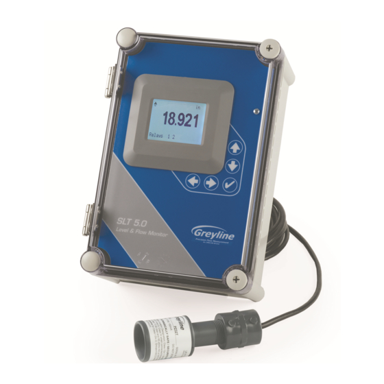
- Page 1 USER'S GUIDE Installation & Operation Instructions Open Channel Flow Monitor Model OCF 5.0 Manual Series A.1.8...
- Page 2 Note: This page has been left blank intentionally.
-
Page 3: Table Of Contents
OCF 5.0 Open Channel Flow Monitor INDEX CONNECTIONS ....................4 KEYPAD SYSTEM.................... 6 CALIBRATION MENU..................7 ICONS......................... 8 MAIN DISPLAY ....................9 MESSAGE ICON ....................9 STATUS......................9 PASSWORD..................... 10 UNITS/MODE ....................11 CALIBRATION....................12 CHANNEL SETUP ..................14 RELAY PARAMETERS.................. 15 DATA LOGGING .................... -
Page 4: Connections
OCF 5.0 Open Channel Flow Monitor CONNECTIONS: POWER INPUT: The standard model requires AC power input between 100 to 240 VAC 50/60Hz. No adjustments are necessary for voltages within this range. Optional DC: 9-32 VDC. Connect to + and - terminals. - Page 5 OCF 5.0 Open Channel Flow Monitor CONNECTIONS Page 5...
-
Page 6: Keypad System
OCF 5.0 Open Channel Flow Monitor KEYPAD SYSTEM The OCF 5.0 uses a menu system. Arrows show the four directions to leave a menu box. Press a key to move to the next item in the direction shown. Move the cursor (highlighted) under numerals and increase or decrease numerals with the ... -
Page 7: Calibration Menu
OCF 5.0 Open Channel Flow Monitor CALIBRATION MENU Page 7... -
Page 8: Icons
OCF 5.0 Open Channel Flow Monitor ICONS Page 8... -
Page 9: Main Display
The main display shows the units selected from the Units/Mode menu, Level, Range, Flow, HRT, and Volume rate being measured, TOTALIZER and RELAY states. The OCF 5.0 will start-up with this display. MESSAGE ICON Press from the main display to view status of the data logger and error/warning messages provided by the instrument. -
Page 10: Password
OCF 5.0 Open Channel Flow Monitor PASSWORD Password (a number from 0000 to 9999) prevents unauthorized access to menu. Calibration From the Main display press to get to . Factory default password is Password 0000 and if it has not been changed press the to proceed to the... -
Page 11: Units/Mode
OCF 5.0 Open Channel Flow Monitor UNITS/MODE press the and then the or to select Mode From Level Range Flow Volume displays distance from the sensor to the target or liquid surface like a Range tape measure. Range mode is useful to measure the exact distance from the sensor to the zero level during calibration. -
Page 12: Calibration
Press and or to change the number of seconds without LOE Time receiving an echo before the OCF 5.0 displays ECHO LOSS, and Control relays change state as calibrated under Relay Parameters. Factory default is 30 seconds and is recommended for most applications, Minimum is 1 second and maximum is 99 seconds. - Page 13 When liquid is at zero level press to view the Range reading in the Status menu. Use this range measured by the OCF 5.0 as the Max Range setting. Carefully measure distance from sensor to zero level with a tape measure,...
-
Page 14: Channel Setup
OCF 5.0 Open Channel Flow Monitor CHANNEL SETUP Page 14... -
Page 15: Relay Parameters
OCF 5.0 Open Channel Flow Monitor RELAY PARAMETERS Press and or to select a relay (2 relays are standard, 4 Relay additional are optional). Press or to select Function Temperature Pulse Flow Air temperature at the sensor location. -
Page 16: Data Logging
OCF 5.0 Open Channel Flow Monitor DATA LOGGING Setup Select Data Logging from Menu Selections. Log Site ID Enter a number from . The site ID will become part of the downloaded file name to help distinguish downloads from different instruments. - Page 17 OCF 5.0 Open Channel Flow Monitor Download letter will be A for the first download from an instrument. B for the second, then C etc. At the letter Z a - character will appear indicating that the maximum number of downloads for that instrument are on the USB flash drive.
-
Page 18: Special Functions
OCF 5.0 Open Channel Flow Monitor SPECIAL FUNCTIONS and press . Language Select English French Spanish Select 4-20mA or 0-5V mode for the analog output. Analog Out Backlight Select High Medium for continuous backlight. Select for high backlight (for 1 minute) - Page 19 OCF 5.0 Open Channel Flow Monitor SIMULATION Exercises the 4-20mA (0-5V) output, digital display and control relays. and press to simulate maximum Flow, Range or Select Test Maximum Level and to output 20mA (5V) to the analog channel. and press to simulate minimum Flow, Range or...
-
Page 20: Sensor Mounting Methods
OCF 5.0 Open Channel Flow Monitor SENSOR MOUNTING METHODS Page 20... - Page 21 OCF 5.0 Open Channel Flow Monitor SENSOR MOUNTING/LOCATION - Open Channel Flow Applications Each sensor is equipped with a 3/4 inch isolation coupling which MUST be used in your installation. A threaded nipple or length of conduit may be used to position the sensor at the desired height. The sensor should be hand-tightened by turning the sensor stem only.
- Page 22 Stilling wells are recommended to reduce the effects of turbulence as water flows through the flume or weir. The OCF 5.0 sensor is centered over the stilling well. Sensor height must be 8" (203 mm) or more above the highest water level.
- Page 23 OCF 5.0 Open Channel Flow Monitor ZERO POSITIONING OF SENSOR - Open Channel Flow Applications Locate the sensor at the position upstream from the throat of the flume or weir plate as recommended by the manufacturer. A technique for accurate sensor height adjustment is shown:...
- Page 24 OCF 5.0 Open Channel Flow Monitor ENCLOSURE INSTALLATION Locate the enclosure within 20 ft (6 m) of the sensor (500 ft -150 m optional). The enclosure can be wall mounted with the four mounting screws (included) or panel mounted with Option PM Panel Mount kit from Greyline Instruments.
-
Page 25: Error/Warning Messages
ECHO LOSS No valid echoes received within the LOE TIME setting. The OCF 5.0 will hold the display and outputs at the last reading until a new echo is received. - or - Your choice of Units exceeds 9,999,999. Use... -
Page 26: Field Troubleshooting
OCF 5.0 Open Channel Flow Monitor FIELD TROUBLESHOOTING SYMPTOMS CHECK Display - full scale - zero - erratic - random - drifting up - drifting down ECHO LOSS prompt - flashing Calibration Non-Linear SYMPTOMS FAULTS SOLUTIONS Unit “See’s” Wrong Target Due To:... - Page 27 OCF 5.0 Open Channel Flow Monitor - sensor cable extended and junction not - Use metal Junction Box insulated - through enclosure - use metal enclosure - through 4-20mA output cable - use shielded twisted pair (shielded to AC ground)
- Page 28 OCF 5.0 Open Channel Flow Monitor PZxx Series Sensors Troubleshooting Resistance measured (between the shield and center wire) across the coaxial cable ends by mulitmeter indicates ambient temperature. Resistance vs. Temperature Page 28...
- Page 29 OCF 5.0 Open Channel Flow Monitor FUSE REPLACEMENT 1. Turn OFF power. 2. Loosen cover screw and open. 3. Remove power module. 4. Locate fuse on Power Board. 5. Replace fuse with 2 AMP/ 250V, 5 x 20mm fuse. 6. Reinstall power module into chassis.
-
Page 30: Applications Hotline
OCF 5.0 Open Channel Flow Monitor APPLICATIONS HOTLINE For applications assistance, advice or information on any Greyline Instrument contact your Sales Representative, write to Greyline or phone the Applications Hotline below: United States: Tel: 315-788-9500 Fax: 315-764-0419 Canada: Tel: 613-938-8956... -
Page 31: Limited Warranty
OCF 5.0 Open Channel Flow Monitor LIMITED WARRANTY _____________________________________ Greyline Instruments warrants, to the original purchaser, its products to be free from defects in material and workmanship for a period of one year from date of invoice. Greyline will replace or repair, free of charge, any Greyline product if it has been proven to be defective within the warranty period. -
Page 32: Appendix A - Options
(152m) as required during installation. No adjustment is required when the sensor cable is extended or shortened. Use only RG62AU (or RG62U) coaxial cable which is available from Greyline Instruments or your local distributor. Nominal impedance of RG62AU cable is 93 ohms. - Page 33 OCF 5.0 Open Channel Flow Monitor EXTENDED SENSOR CABLE INSTALLATION IN MANHOLE Page 33...
- Page 34 OCF 5.0 Open Channel Flow Monitor SENSOR INTRINSIC SAFETY (OPTION ISB) When connected through Intrinsic Safety Barriers, Greyline PZ** Series sensors are certified for installation in a hazardous location rated: Class I, Groups C,D Class II, Groups E,F,G Class III The Intrinsic Safety Barrier may be ordered with the Greyline instrument and is supplied mounted in the Greyline instrument enclosure.
- Page 35 OCF 5.0 Open Channel Flow Monitor Page 35...
- Page 36 OCF 5.0 Open Channel Flow Monitor ENCLOSURE HEATER AND THERMOSTAT - Option TH Instruments can be factory-equipped with an Enclosure Heater and Thermostat or the module can be customer-installed. The Thermostat is factory set to turn ON at 40°F (4.5°C) and OFF at 60°F (15.5°C).
- Page 37 LCD display. Test operation of the OCF 5.0 by holding the sensor steadily and aiming at a flat, stable target 12 to 28" (305 to 711 mm) away from the end of the sensor. Allow a few seconds for the OCF 5.0 to lock onto the target before displaying its distance.
-
Page 38: Conversion Guide
OCF 5.0 Open Channel Flow Monitor CONVERSION GUIDE FROM MULTIPLY BY US GALLONS CUBIC FEET 0.1337 US GALLONS IMPERIAL GALS 0.8327 US GALLONS LITRES 3.785 US GALLONS CUBIC METERS 0.003785 LITRES/SEC 15.85 LITRES CUBIC METERS 0.001 BARRELS US GALLONS BARRELS IMPERIAL GALS 34.9726... -
Page 39: Specifications
OCF 5.0 Open Channel Flow Monitor SPECIFICATIONS Accuracy: ±0.25% of Range or 2 mm, whichever is greater Repeatability and Linearity: 0.1% F.S. Displays: White, backlit matrix - displays flow rate, totalizer, relay states, operating mode and calibration menu Calibration: built-in 5-key calibrator... - Page 40 OCF 5.0 Open Channel Flow Monitor Optional Sensor PZ32T Maximum Range: 32 ft. (10 m) Deadband (blanking): Programmable, minimum 12” (305 Beam Angle: 8° at 3 DB Temperature Compensation: Automatic, continuous Operating Frequency: 42 KHz Exposed Materials: PVC and Teflon Operating Temperature: - 40°...
Need help?
Do you have a question about the OCF 5.0 and is the answer not in the manual?
Questions and answers