
Related Manuals for Greyline Instruments DFM-IV


Summary of Contents for Greyline Instruments DFM-IV
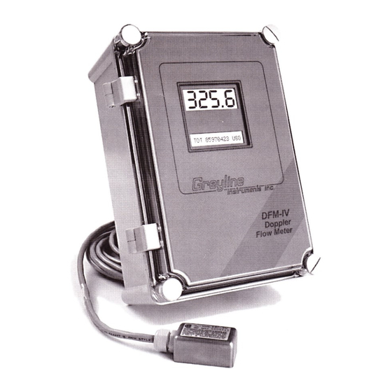
- Page 1 USER’S GUIDE Installation & Operation Instructions Doppler Flow Meter Model DFM-IV Manual Series A.6...
-
Page 2: Table Of Contents
DFM-IV Doppler Flow Meter Manual Series A.6 INDEX Bench Test · · · · · · · · · · · · · · · · · · · · · · · · · · · · · · · · · · · · · · · · · · · · · · · · · · · · · · · 3 Connections·... -
Page 3: Bench Test
Manual Series A.6 QUICK BENCH TEST: Connect Sensor as shown below, then Power. Test operation of the DFM-IV by holding the sensor in one hand and rubbing your thumb or fingers briskly across the face (plastic surface) of the sensor. -
Page 4: Keypad System
MENU - FLOW CHART The following diagram shows the DFM-IV Menu system. Arrows show the three directions to leave a box. Pressing a corresponding keypad arrow will move to the next box in the direction shown. Move the cursor (or underline) under numerals and increase or decrease numerals with the È and Ç keys. -
Page 5: Calibration Menu
DFM-IV Doppler Flow Meter Manual Series A.6 Calibration Menu Page 5... -
Page 6: Totalizer
DFM-IV Doppler Flow Meter Manual Series A.6 PASSWORD A scrolling display shows the units selected from the units selection Tot: 1098 column, the mode of operation (VELOCITY or FLOW), the full scale value for the large numeric display and the TOTALIZER value. -
Page 7: Relay Status Display
- Reverse character indicates that the Relay is On (energized). 2 3 4 5 24 HR LOG DFM-IV Flow Meters with optional Data Logger will display this menu. Refer to OPTIONS section. PASSWORD The password (a number from ) prevents unauthorized access to the menu. -
Page 8: Calibration
( entry is required only to set 20mA output at a specific MaxF flow rate and maximum flow in the optional data logger. setting has no effect on the DFM-IV MaxF digital display, totalizer, or control relays). 4-20mA CURRENT LOOP Some applications may require the 4-20mA output to be offset so that 4mA or 20mA correspond to flow rates other than Zero and Maximum. -
Page 9: Relay Parameters
DFM-IV Doppler Flow Meter Manual Series A.6 RELAY PARAMETERS RELAY PARAMETERS RELAY PARAMETERS CALIBRATION R1 Function Off Pulse Flow R1on 100 ft3 R1on 100.0 ft3/s 0.00 ft3/s Store? *** STORING *** Set Relays 1-3 (4-5 optional) to Off , Pulse or Flow. -
Page 10: Special Functions
Master or Slave (see Manual section SYNCHRONIZATION). position cursor under digits and set new number between New Password (Optional) set the baud rate of the DFM-IV RS232 output when equipped with Com 24 48 96 192 an optional data logger. Page 10... -
Page 11: Sensor Mounting
DFM-IV Doppler Flow Meter Manual Series A.6 SENSOR MOUNTING LOCATION The position of the sensor is one of the most important considerations for accurate Doppler flow measurement. The same location guidelines apply to Doppler as most other types of flow meters. - Page 12 DFM-IV Doppler Flow Meter Manual Series A.6 SENSOR MOUNTING Prepare an area 2" wide by 4" long (50mm x 100mm) for sensor bonding by removing loose paint, scale and rust. The objective of site preparation is to eliminate any discontinuity between the sensor and the pipe wall, which would prevent acoustical coupling.
- Page 13 Warm temperatures, moisture and vibration will accelerate this process. Dow Corning Silicone Compound #4 as supplied with the DFM-IV (and available from Greyline Instruments) is recommended for semi-permanent installations. Page 13...
- Page 14 DFM-IV Doppler Flow Meter Manual Series A.6 SENSOR MOUNTING/COUPLING RECOMMENDATIONS GOOD Page 14...
-
Page 15: Enclosure Installation
DFM-IV Doppler Flow Meter Manual Series A.6 ENCLOSURE INSTALLATION Locate the enclosure within 20 ft (6 m) of the sensor (500 ft -150 m optional). The enclosure can be wall mounted with the four mounting screws (included) or panel mounted with Option PM Panel Mount kit from Greyline Instruments. -
Page 16: Synchronization
DFM-IV flow meters if: - sensors from separate DFM-IV flow meters are mounted on the same pipe - extended sensor cables from separate DFM-IV flow meters are run in the same conduit To synchronize two or more DFM-IV flow meters: 1. -
Page 17: Backflow Rejection
Typically the external relay will be energized or de-energized in tandem with a pump or control valve. The external relay must be voltage free (the DFM-IV generates a low-voltage DC current across the INPUT terminals). In response to the external relay contact closure the DFM-IV display and outputs will... -
Page 18: Error/Warning Messages
DFM-IV Doppler Flow Meter Manual Series A.6 ERROR/WARNING MESSAGES The value entered for must be greater than 0.5 inches (1.26 cm) E: ILLEGAL I.D. Pipe ID and less than 180 inches (457.3 cm). The value entered for (maximum flow) is too low or too high. -
Page 19: Troubleshooting
(<1 ohm resistance). · Ensure 4-20mA Shield connected to Instrument Ground stud. · Reduce DFM Sensitivity setting. Cross talk between two or more DFM-IV · Turn OFF one flowmeter or follow flowmeters on same pipe synchronization procedure for two or more DFM-IV Flowmeters. - Page 20 DFM-IV Doppler Flow Meter Manual Series A.6 Possible Causes: Corrective Action: Valve leak or Reverse flow · Test Valve. Relocate Sensor farther from valve · Use Backflow Rejection Sensor connections incorrect · Refer to Connections diagram METER READING ERRATIC Sensor mounted too close to valve, pump or ·...
- Page 21 DFM-IV Doppler Flow Meter Manual Series A.6 Possible Causes: Corrective Action: Variable Speed Drive interference · Follow Drive manufacturers wiring and Grounding instructions · Relocate Flowmeter electronics, Sensor and wiring away from VSD METER READING DOES NOT TRACK FLOW Sensor and GND wires reversed or not properly ·...
-
Page 22: Common Questions And Answers
DFM-IV Doppler Flow Meter Manual Series A.6 COMMON QUESTIONS AND ANSWERS The pipe vibrates. Will it affect the flow meter? Common vibration frequencies are far lower than the sonic frequencies used by the Greyline flow meter, and will not normally affect accuracy or performance. However, applications where very weak Doppler signal is present (when sensitivity is adjusted to maximum and signal strength is low), accuracy may be affected by pipe vibration, or the flow meter may show readings under no-flow conditions. - Page 23 (Greyline Option JB). BNC coaxial connectors (TV cable type) are not recommended for cable splices. Does the DFM-IV require periodic recalibration? No. DFM-IV calibration does not drift over time. The solid state sensor has no moving parts to wear and affect calibration. The Doppler flow technique generates an ultrasonic signal proportional to the velocity of flow.
-
Page 24: Applications Hotline
DFM-IV Doppler Flow Meter Manual Series A.6 APPLICATIONS HOTLINE For applications assistance, advice or information on any Greyline Instrument contact your Sales Representative, write to Greyline or phone the Applications Hotline below: United States: Tel: 315-788-9500 Fax: 315-764-0419 Canada: Tel: 613-938-8956... -
Page 25: Flow Meter Data Sheet
DFM-IV Doppler Flow Meter Manual Series A.6 FLOW METER DATA SHEET Greyline Instruments Inc. Please complete and return this form to Greyline. It is 16456 Sixsmith Dr., Long Sault, Ont. K0C 1P0 important. We use this information to check our database... -
Page 26: Warranty
Manual Series A.6 LIMITED WARRANTY ______________________ Greyline Instruments warrants, to the original purchaser, its products to be free from defects in material and workmanship for a period of one year from date of invoice. Greyline will replace or repair, free of charge, any Greyline product if it has been proven to be defective within the warranty period. -
Page 27: Appendix A - Options
DFM-IV Doppler Flow Meter Manual Series A.6 APPENDIX A – OPTIONS EXTRA SENSOR CABLE (OPTION DXC) Each Greyline flow meter includes 20 ft / 6m (or 50 ft / 15 m optional) continuous shielded coaxial pair cable. Additional cable and Cable Junction Box (Option DJB) may be ordered with the Flow Meter, or the cable may be spliced and extended up to 500 ft (152m) as required during installation. - Page 28 DFM-IV Doppler Flow Meter Manual Series A.6 SENSOR INTRINSIC SAFETY (OPTION 2ISB) When connected through INTRINSIC SAFETY BARRIER Intrinsic Safety Barriers, the INTRINSIC SAFETY BARRIER Greyline Sensor Model SE3 is CSA certified for installation in a hazardous location rated: Class I, Groups C,D...
- Page 29 DFM-IV Doppler Flow Meter Manual Series A.6 ENCLOSURE HEATER AND THERMOSTAT - Option TH Instruments can be factory-equipped with an Enclosure Heater and Thermostat. The Thermostat is factory set to turn ON at 40°F (4.5°C) and OFF at 60°F (15.5°C). Power consumption is 15 Watts.
- Page 30 DFM-IV Flow Meters may be ordered factory-configured for 12VDC, or 24VDC power input. QUICK BENCH TEST: Connect Sensor as shown below, then Power. Test operation of the DFM-IV by holding the sensor in one hand and rubbing your thumb or fingers briskly across the face (plastic surface) of the sensor.
- Page 31 DFM-IV Doppler Flow Meter Manual Series A.6 INSERTION FLOW SENSOR 20' (6 m) CONTINUOUS (OPTION ISE) SHIELDED COAXIAL PAIR (50' / 15 m OPTIONAL) MARKER POINTS Insertion Depth: 1/8th pipe inside diameter plus 3/4" (20 mm). UPSTREAM ADJUSTABLE SWAGE-LOCK FITTING Orientation: Screw head marks the active face and should point upstream ±5°.
-
Page 32: Data Logger
DFM-IV Doppler Flow Meter Manual Series A.6 Data Logger Menu (Optional) PASSWORD: 00 DATA LOGGING UNITS / MODE STOP Setup Session No Log Site ID Formatted Trend StartJan 01/2000 Time Event Start 03:02:16 StartJan 01/2000 HiAlm LoAlm nterval: 24 Hr... - Page 33 8 Hrs 4 Hrs 1 Hrs Press Æ to return to Press È and the DFM-IV will report indicating Interval. xxxxx Hrs Left the amount of logging time available with your current set-up. You can also press Ç to return to previous menu items and make changes.
- Page 34 Viewing FORMATTED Data Logs on the DFM-IV Display press Æ to 24 Hour Formatted logs can be viewed directly on the DFM-IV display. From 24 HR . This function is available only if 24 Hour Formatted logging has been Stored from the DATA LOGGING menu.
- Page 35 È. To keep existing data in the Log press È from If you have made changes Reset Log? to the Start Date, Time or Interval, the data logger will automatically start a new “session”. The DFM-IV will display “ ”.
- Page 36 From the Data Logging prompt the menu will return to Store? Yes RUN STOP SETUP and press È to activate the Data Logger to start. The DFM-IV will position the cursor under . Press È to return to display SESSION NO. x DATA LOGGING Logging "Sessions"...
-
Page 37: Rs232C Serial Output
DFM-IV Doppler Flow Meter Manual Series A.6 RS232C SERIAL OUTPUT (with optional Data Logger) Format: 8 Bits, 1 Stop Bit, No Parity. (Baud rate may be changed under the SPECIAL FUNCTIONS menu. Factory default is 19200 baud). Output connector is DB9-Female. Use the cable supplied for connection to a PC Computer. Use the cable and optional Null Modem NM-DB9M/DB25M for connection to a modem. - Page 38 Factory default is 19200 baud). Use shielded, 4-conductor cable (Greyline cable option SC-18AWG recommended). Connect the cable shield to Ground at the DFM-IV electronics enclosure and do not connect to Ground at the other end. RS232 Cable RS232/485 Converter...
-
Page 39: Specifications
DFM-IV Doppler Flow Meter Manual Series A.6 SPECIFICATIONS 7.4 / 188 mm " 6.46 / 164 mm " 5.12 / 130 mm " Flow Rate Range: 0.25 to 40 ft/sec ((0.08 to 12.2 m/sec) in most applications Pipe Size: Any pipe ID from 0.5" to 180"... -
Page 40: Appendix B - Conversion Table
DFM-IV Doppler Flow Meter Manual Series A.6 APPENDIX B - CONVERSION TABLE CONVERSION GUIDE FROM MULTIPLY BY US GALLONS CUBIC FEET 0.1337 US GALLONS IMPERIAL GALS 0.8327 US GALLONS LITRES 3.785 US GALLONS CUBIC METERS 0.003785 LITRES/SEC 15.85 LITRES CUBIC METERS 0.001... -
Page 41: Pipe Charts
DFM-IV Doppler Flow Meter Manual Series A.6 PIPE CHARTS Carbon Steel & PVC Pipe Pipe Pipe Standard Extra Heavy Dbl. Extra Heavy Schedule 10 Schedule 20 Schedule 30 Schedule 40 Size O.D. I.D. WALL I.D. WALL I.D. WALL I.D. WALL I.D. - Page 42 DFM-IV Doppler Flow Meter Manual Series A.6 Stainless Steel, Hastelloy "C" & Titanium Pipe Pipe Pipe Schedule 5 S (a) Schedule 10 S (a) Schedule 40 S Schedule 80 S Size O.D. I.D. WALL I.D. WALL I.D. WALL I.D. WALL ½...
- Page 43 DFM-IV Doppler Flow Meter Manual Series A.6 Cast Iron Pipe - ASA Standard Pipe Pipe Class Class Class Class Class Class Class Size O.D. WALL I.D. WALL I.D. WALL I.D. WALL I.D. WALL I.D. WALL I.D. WALL I.D. 3.96 0.32 3.32...
-
Page 44: Calibration Record
DFM-IV-CALIBRATION RECORD - Circle selected units and enter Values in blank spaces...
Need help?
Do you have a question about the DFM-IV and is the answer not in the manual?
Questions and answers