
Subscribe to Our Youtube Channel
Related Manuals for Greyline Instruments SLT32


Summary of Contents for Greyline Instruments SLT32
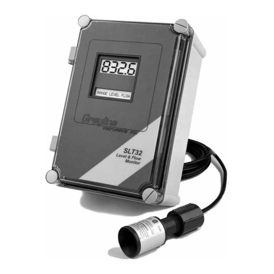
- Page 1 USER’S GUIDE Installation & Operation Instructions Level & Flow Monitor Model SLT32 Manual Series B.11...
- Page 2 Note: This page has been left blank intentionally.
-
Page 3: Table Of Contents
SLT32 Level & Flow Monitor Manual Series B.11 INDEX BenchTest · · · · · · · · · · · · · · · · · · · · · · · · · · · · · · · · · · · · · · · · · · · · · · · · · · · · · · · · 4 Connections·... -
Page 4: Benchtest
LCD display. Test operation of the SLT32 by holding the sensor steadily and aiming at a flat, stable target 12 to 28" (305 to 711 mm) away from the end of the sensor. -
Page 5: Keypad System
MENU - FLOW CHART The following diagram shows part of the SLT32 Menu system. Arrows show the three directions to leave a box. Pressing a corresponding keypad arrow will move to the next box in the direction shown. -
Page 7: Run
From RUN use È to get to the Echo Confidence display, Echo Strength Arrow TOTALIZER The Totalizer display will only be enabled when the SLT32 is calibrated in mode. From FLOW È or Ç keys to display value. The Totalizer value is updated every 2 seconds with flow volume Tot: 1 litre (0.264 USG). -
Page 8: Password
Volume mode displays tank inventory in engineering units like gallons or liters. Horizontal Round Tank mode sets the SLT32 to calculate and display volume units in a horizontal round tank. mode is for open channel flow through a flume or weir. - Page 9 È . MxVol You can enter values up to 6 digits (e.g. 150,000 liters). When the measured tank volume exceeds 4 digits, the SLT32 will automatically display a ‘multiplier’ on the lower alphanumeric display. = 150,000 Liters UNITS 1000L...
-
Page 10: Flume Selection
SLT32 Level & Flow Monitor Manual Series B.11 FLUME SELECTION menu will only appear in mode. FLUME SELECTION FLOW Use È and Æ to select the correct Flume or Weir. FLOW MODE ONLY UNITS/MODE FLUME SELECTION CALIBRATION V-Notch > Parshall >... -
Page 11: Calibration - For Level
(any value 0). In Level or Range modes the SLT32 will only accept MinRg values 8" (20.3 cm). VOLUME - Press Æ to return to MinRg... -
Page 12: Calibration- For Open Channel Flow
Store? Yes (NOTE: flow must be at zero flow) SENSOR Carefully measure distance from sensor to zero RANGE level with tape measure. MAX LEVEL NOTE: The SLT32 will not detect targets beyond user RANGE entered MaxRg ZERO LEVEL Page 12... -
Page 13: 4-20Ma Current Loop Offset
A value of 20% is recommended for most applications. For fast level changes (up to ½ inch/sec - 13 mm/sec), a Damping value of 1% is recommended. Maximum is 99%. If the SLT32 is unable to obtain repeated echoes the Damping setting will be automatically set to 1% by the instrument. -
Page 14: Relay Parameters
Maximum pulse setting is 999,999. Minimum time between pulses is 1 second and pulse duration is 350 milliseconds. References temperature reading from the SLT32's ultrasonic sensor (air temperature at the Temp sensor location). Press È and Æ and set the relay On and Off set points. - Page 15 SLT32 Level & Flow Monitor Manual Series B.11 Appears in Flow mode only. Press È to and Æ to select (low Flow R Function Pump LoAlm alarm) or (high alarm). HiAlm mode - press È and Æ and set relay On and Off set point.
-
Page 16: Special Functions
SLT32 Level & Flow Monitor Manual Series B.11 SPECIAL FUNCTIONS SPECIAL FUNCTION SLT32 V 2.77 iew Codes? 1234567890123456 Date May 31/1999 Time 23:39:51 LOE Time 30 s FLOW MODE ONLY Reset Tot? Temp 20.3 C º Min Temp 20.0 C º... - Page 17 Indicates current temperature at the sensor head. Press Æ to and Æ Temp 25.0C Min Temp to display the minimum and maximum temperatures the SLT32 Max Temp has sensed. Press Æ to Display ° ° . Position the cursor under °...
-
Page 18: Sensor Mounting/Location - Tank Level
SLT32 Level & Flow Monitor Manual Series B.11 SENSOR MOUNTING/LOCATION - Tank Level/Inventory Applications GOOD Each SLT32 Level Transmitter includes a 90° non-contacting ultrasonic sensor. The sensor must be installed in a position to obtain unobstructed echoes from the liquid or material being measured. - Page 19 SLT32 Level & Flow Monitor Manual Series B.11 SENSOR MOUNTING LOCATION - Tank Level/Inventory Applications PREFERRED SENSOR LOCATION 1 FT (30 cm) HORIZONTAL FROM SIDEWALL FOR 6" SCHEDULE 40 EVERY 10' (3 m) VERTICAL STAND PIPE IF EXTENSION NOTE: 2 FT (60 cm) FOR...
- Page 20 SLT32 Level & Flow Monitor Manual Series B.11 Notes: 1. Use the ¾" NPT "Isolation Coupling" supplied and hand only. Do not clamp sensor tighten FLANGE MOUNT body or stem. FLEXIBLE 2. Locate the sensor 1 ft (30 cm) from...
-
Page 21: Sensor Mounting/Location - Open Channel Flow
SLT32 Level & Flow Monitor Manual Series B.11 SENSOR MOUNTING/LOCATION - Open Channel Flow Applications Each sensor is equipped with a 3/4 inch isolation coupling which MUST be used in your installation. A threaded nipple or length of conduit may be used to position the sensor at the desired height. The sensor should be hand-tightened by turning the sensor stem only. - Page 22 Stilling wells are recommended to reduce the effects of turbulence as water flows through the flume or weir. The SLT32 sensor is centered over the stilling well. Sensor height must be 12" / 30.5 cm or more above the highest water level. The well must be kept clean of sediments and deposits on the side walls.
- Page 23 SLT32 Level & Flow Monitor Manual Series B.11 ZERO POSITIONING OF SENSOR - Open Channel Flow Applications Locate the sensor at the position upstream from the throat of the flume or weir plate as recommended by the manufacturer. A technique for accurate sensor height adjustment is shown:...
-
Page 24: Enclosure Installation
Locate the enclosure within 500 ft (150 m) of the sensor. It can be wall mounted with four mounting screws (supplied) or panel mounted with Option PM Panel Mounting Kit from Greyline Instruments. Avoid mounting the enclosure in direct sunlight to protect the electronics from damage due to overheating and condensate. -
Page 25: Error/Warning Messages
See FIELD "ECHO LOSS" LOE TIME TROUBLESHOOTING (F). In mode the SLT32 will hold the Level display and outputs at the last reading until a new echo is received. In mode it will display and totalization will stop until an echo is FLOW 0.00... -
Page 26: Field Troubleshooting
SLT32 Level & Flow Monitor Manual Series B.11 FIELD TROUBLESHOOTING SYMPTOMS CHECK Display - full scale - zero - erratic - random - drifting up - drifting down prompt - flashing ECHO LOSS Calibration Non-Linear SYMPTOMS FAULTS SOLUTIONS Unit “See’s” Wrong Target Due To:... - Page 27 SLT32 Level & Flow Monitor Manual Series B.11 - through 4-20mA output cable - use shielded twisted pair (shielded to AC ground) - use grounded metal conduit - wiring or installation close to - follow V.S.D. manufacturer’s instructions variable speed drive or inverter...
- Page 28 SLT32 Level & Flow Monitor Manual Series B.11 FUSE REPLACEMENT 1. Turn OFF power 2. Loosen 2 Phillips corner screws and remove power module from the chassis. 3. Locate fuse on Power Board 4. Replace fuse with 2 Amp/250V, 5 x 20mm fuse 5.
-
Page 29: Installation Considerations In Noisy Environments
SLT32 Level & Flow Monitor Manual Series B.11 INSTALLATION CONSIDERATIONS IN NOISY ENVIRONMENTS Greyline’s instruments are designed with a high degree of noise immunity for use in industrial environments. Noise interference can still occur if certain minimal considerations are not adhered to when installing the equipment. - Page 30 SLT32 Level & Flow Monitor Manual Series B.11 Avoiding noise problems 1. It is recommended that electronic instruments be connected to a relatively clean AC power source. Use an AC power filter or isolation transformer if necessary. 2. The sensor input line and the control lines (AC or DC) should not be run in the same conduit . The sensor input should be separated from wires going to inductive loads such as motors, solenoids, relays and contactors.
-
Page 31: Applications Hotline
SLT32 Level & Flow Monitor Manual Series B.11 APPLICATIONS HOTLINE For applications assistance, advice or information on any Greyline Instrument contact your Sales Representative, write to Greyline or phone the Applications Hotline below: United States: Tel: 315-788-9500 Fax: 315-764-0419 Canada:... -
Page 32: Product Return Procedure
SLT32 Level & Flow Monitor Manual Series B.11 PRODUCT RETURN PROCEDURE Instruments may be returned to Greyline for service or warranty repair. Obtain an RMA Number from Greyline - Before shipping a product to the factory please contact Greyline by telephone, fax or email to obtain an RMA number (Returned Merchandise Authorization). -
Page 33: Warranty
Manual Series B.11 LIMITED WARRANTY ______________________ Greyline Instruments warrants, to the original purchaser, its products to be free from defects in material and workmanship for a period of one year from date of invoice. Greyline will replace or repair, free of charge, any Greyline product if it has been proven to be defective within the warranty period. -
Page 34: Appendix A - Options
EXTRA SENSOR CABLE (OPTION XC) Each Greyline SLT32 includes 25 ft. (7.6m) RG62AU coaxial cable. Additional RG62AU coaxial cable and Cable Junction Box (Option JB) may be ordered with the Flow Monitor, or the cable may be spliced and extended up to 500 ft (152m) as required during installation. No adjustment is required when the sensor cable is extended or shortened. - Page 35 SLT32 Level & Flow Monitor Manual Series B.11 SENSOR INTRINSIC SAFETY - OPTION ISB SENSOR MODELS PZ32T/PZ32TE/PZ12 (with built-in temperature compensation) When connected through an Intrinsic Safety Barrier, the Greyline PZ32T and PZ32TE sensors are CSA certified for installation in a hazardous location rated:...
- Page 36 SLT32 Level & Flow Monitor Manual Series B.11 ENCLOSURE HEATER AND THERMOSTAT - Option TH Instruments can be factory-equipped with an Enclosure Heater and Thermostat. The Thermostat is factory set to turn ON at 40°F (4.5°C) and OFF at 60°F (15.5°). Power consumption is 15 Watts.
- Page 37 12 to 28" (305 to 711 mm) away from the end of the sensor. Allow a few seconds for the SLT32 to lock onto the target before displaying its distance. The SLT32 will now display Range in ft or cm (factory calibration).
-
Page 38: Data Logger
SLT32 Level & Flow Monitor Manual Series B.11 DATA LOGGER MENU (Optional) PASSWORD: 00 DATA LOGGING UNITS / MODE STOP Setup Session No Log Site ID Formatted Trend StartJan 01/2000 Time Event StartJan 01/2000 HiAlm LoAlm Start 03:02:16 nterval: 24 Hr... - Page 39 . Press Æ to and then È to reset the Log and erase all previous Reset Log? Yes sessions and stored values. Or press È from to retain existing data in the Log. The SLT32 Reset Log? will display “ ”.
- Page 40 Viewing FORMATTED Data Logs on the SLT32 Display press Æ to 24 Hour Formatted logs can be viewed directly on the SLT32 display. From 24 HR . This function is available only if 24 Hour Formatted logging has been Stored from the Data Logging menu.
- Page 41 È. To keep existing data in the Log press È from If you have made changes Reset Log? to the Start Date, Time or Interval, the data logger will automatically start a new “session”. The SLT32 will display “ ”.
- Page 42 . Press Æ to Store? Yes RUN STOP SETUP and press È to activate the Data Logger to start. The SLT32 will display position the cursor under . Press È to return to SESSION NO. x DATA LOGGING Note: Greyline Logger software cannot accurately calculate totals from 'event' based log files.
-
Page 43: Rs232C Serial Output
SLT32 Level & Flow Monitor Manual Series B.11 RS232C SERIAL OUTPUT (with optional Data Logger) Format: 8 Bits, 1 Stop Bit, No Parity. (Baud rate may be changed under the SPECIAL FUNCTIONS menu. Factory default is 19200 baud). Output Connector is DB9-Female. Use the cable supplied for connection to a PC Computer. Use the cable and optional Null Modem NM-DB9M/DB25M for connection to modem. - Page 44 Factory default is 19200 baud). Use shielded, 4-conductor cable (Greyline cable option SC-18AWG recommended). Connect the cable shield to Ground at the SLT32 electronics enclosure and do not connect to Ground at the other end. RS232 Cable RS232/485 Converter...
- Page 45 SLT32 Level & Flow Monitor Manual Series B.11 ENCLOSURE SUNSCREEN - OPTION SCR Do not mount instrument electronics in direct sunlight. Overheating will reduce the life of electronic components and condensate may form during the heat/cool cycles and cause electrical shorts.
-
Page 46: Appendix B - Applications Background
(1/8 in. or less) can generally be disregarded. Use a stilling well in open channel applications. LIQUIDS - The SLT32 is ideal to monitor tank liquid level or inventory. Caustic, corrosive or very viscous liquids can be monitored without contacting the liquid. -
Page 47: Conversion Guide
SLT32 Level & Flow Monitor Manual Series B.11 CONVERSION GUIDE FROM MULTIPLY BY US GALLONS CUBIC FEET 0.1337 US GALLONS IMPERIAL GALS 0.8327 US GALLONS LITRES 3.785 US GALLONS CUBIC METERS 0.003785 LITRES/SEC 15.85 LITRES CUBIC METERS 0.001 BARRELS US GALLONS... -
Page 48: Specifications
SLT32 Level & Flow Monitor Manual Series B.11 SPECIFICATIONS 7.4 / 188 mm " 6.46 / 164 mm " 5.12 / 130 mm " Electronics Enclosure: NEMA4X (IP 66), watertight and dust tight, fiberglass with clear, shatterproof hinged Lexan cover Accuracy: 0.25% F.S.,... - Page 49 SLT32 Level & Flow Monitor Manual Series B.11 Optional Sensor PZ32TE 25' (7.6 m) RG62AU 3/4" COAXIAL CABLE Maximum Range: 32 ft. (10 m) Deadband (blanking): Programmable, minimum 12” (305 TEFLON ISOLATION COUPLING (SUPPLIED) Beam Angle: 8° at 3 DB Temperature Compensation: Automatic, continuous 3/4"...
- Page 50 SLT32 Level & Flow Monitor Manual Series B.11 Optional PZ12 25 ft (7.6 m) RG62AU COAXIAL CABLE Maximum Range: 12 ft (3.66 m) (50 ft 15 m OPTIONAL) Minimum Range (Deadband): 8" (203.2 mm) Operating Frequency: 92 KHz 3/4“ NPT Beam Angle: 8°...
- Page 51 SLT32 Level & Flow Monitor Manual Series B.11 Optional PZ34 25 ft (7.6 m) RG62AU COAXIAL CABLE (50 ft 15 m OPTIONAL) Maximum Range: 32 ft. (10 m) 3/4“ NPT Minimum Range (Deadband): 16" (406.4 mm) Operating Frequency: 46 KHz ISOLATION Beam Angle: 8º...
-
Page 52: Calibration Worksheet - Level
LEVEL ___ + ___ = ___________ VOLUME MAX RG = MIN RANGE for Vertical STORE MAX. VOL Tanks ___ + ___ - ___ = ___________ MIN RG NOTE: The SLT32 will not detect targets beyond user entered MaxRg Page 52... -
Page 53: Calibration Worksheet - Flow
Program MIN RANGE then MAX RANGE via: MAX HEAD B =________________ CALIBRATION (Height at MAX Flow) MODE MIN RANGE MIN RANGE MAX RANGE ______ - ______ ____________ STORE? NOTE: The SLT32 will not detect targets beyond the user entered MaxRg Page 53...
Need help?
Do you have a question about the SLT32 and is the answer not in the manual?
Questions and answers