Table of Contents
Advertisement
Quick Links
Advertisement
Table of Contents
Troubleshooting

Subscribe to Our Youtube Channel
Related Manuals for Greyline Instruments PORTAFLOW PT500


Summary of Contents for Greyline Instruments PORTAFLOW PT500
- Page 1 PORTAFLOW PT500 Portable Ultrasonic Flowmeter User’s Guide www.greyline.com...
- Page 2 Note: This page has been left blank intentionally Page www.greyline.com...
-
Page 3: Table Of Contents
Table of Contents 1: General Description........................5 1.1 Introduction........................5 1.2 Principles of Operation ......................6 1.3 Supplied Hardware ......................7 1.4 Portaflow PT500 Instrument....................8 1.4.1 Connectors ......................8 1.4.2 Keypad........................9 1.4.3 Power supply and battery charging ..............10 1.5 Transducers........................10 2: Installation………………………………………….…………………………………………………11 2.1 Transducer Positioning....................11 2.2 Transducer Attachment (Type ‘A’... - Page 4 3.6.4 How to log directly to a PC .................33 3.6.5 How to download logged data to a PC ...............34 3.7 Configuring the Portaflow PT500 Interfaces ..............34 3.7.1 How to set-up an RS232 connection ..............34 3.7.2 How to set-up a USB connection................36 3.7.3 How to turn the 4-20mA output OFF/ON............36...
-
Page 5: 1: General Description
1: General Description 1.1 Introduction This manual describes the operation of the Greyline Portaflow PT500 portable flowmeter. The flowmeter is designed to work with clamp-on transducers to enable the flow of a liquid within a closed pipe to be measured accurately without needing to insert any mechanical parts through the pipe wall or protrude into the flow system. -
Page 6: Principles Of Operation
The Portaflow PT500 system employs two ultrasonic transducers attached to the pipe carrying the liquid and compares the time taken to transmit an ultrasound signal in each direction. If the sound characteristics of the fluid are known, the Portaflow microprocessor can use the results of the transit time calculations to compute the fluid flow velocity. -
Page 7: Supplied Hardware
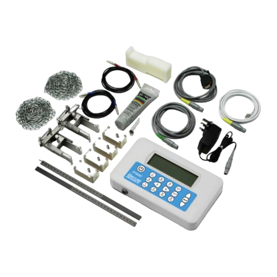
Portaflow PT500 Instrument Figure 1.2 Standard Portaflow equipment Standard equipment • Portaflow PT500 instrument with backlit graphic display • Power supply - with UK, US, European adaptors. 110/240VAC • 4-20mA/Pulse Output cable, USB cable and RS232-C cable • 2 lengths of chain each at 3.3 metres long •... -
Page 8: Portaflow Pt500 Instrument
RS232 and USB connections RS232 and USB cables are included as part of the Portaflow PT500 kit. These can be connected to the yellow 8- pin connector on the top of the flowmeter as shown in Figure 1.3. -
Page 9: Keypad
Menus and the menu selection keys The Portaflow PT500 menus are arranged hierarchally with the MAIN MENU being at the top level. Menu navigation is achieved by three keys on the right hand side of the keypad which are used to scroll UP and DOWN a menu list and SELECT a menu item. -
Page 10: Power Supply And Battery Charging
Supplied as standard for use on pipes 1.97” to 78.74” (50mm to 2000mm) outside diameter. Transducer set 'D' Type 'D' transducers are optional equipment that can be used by the Portaflow PT500 on pipes from 59” to 196” (1500mm to 5000mm). They are supplied complete with ratchet straps for ‘diagonal mode’ attachment. -
Page 11: 2: Installation
Installation Transducer Positioning In many applications an even flow velocity profile over The Portaflow equipment expects a uniform flow profile as a a full 360° is unattainable due, for example, to the distorted flow will produce unpredictable measurement presence of air turbulence at the top of the flow and errors. -
Page 12: Transducer Attachment (Type 'A' & 'B')
Transducer Attachment (Type ‘A’ & ‘B’) Type ‘A’ & ‘B’ transducers are fitted to adjustable guide rails which are secured to the pipe using wrap-around chains and mechanically connected together by a steel separation bar. The separation bar also acts as a ruler to allow the distance between the transducers to be accurately set to the value determined by the Portaflow instrument. -
Page 13: Fitting The Transducers
On each guide rail, attach one end of a securing chain to a hook on the tensioning bar (B), wrap the chain around the pipe (G) and then attach it to the hook on the other end of the tensioning bar whilst keeping the chain as tight as possible. -
Page 14: Installing The Usb Virtual Com. Port
14. Select OK to implement the change, and then close the remaining windows that were opened. 15. Your computer should now be able to communicate with the Portaflow PT500 instrument via the USB port in the same way as any other standard USB device. -
Page 15: 3: Operating Procedures
3: Operating Procedures Initial instrument setup (Paragraph 3.1) Battery charging, Set date/time, Language, Backlight Connect and take basic flow readings At a one-off location At a frequent location Manage site details (Paragraph 3.2) (Paragraph 3.3) (Paragraph 3.4) QUICK START VIEW EDIT SITE DATA Set up a named site Rename a site Choose site / check data... -
Page 16: Setting-Up The Instrument
3.1.1 Using the instrument for the first time Before you use your Portaflow PT500 for the first time you should first charge the battery, then select the display language and set-up the internal clock, as described below. Charging the battery Connect the external battery charger to the charger socket at the bottom of the instrument then switch on the utility supply. -
Page 17: Enabling/Disabling The Backlight
If the point at which you intend to take the measurement is likely to require regular monitoring it is best to set it up as a ‘Site’ within the Portaflow PT500, which then stores the site parameters (See Managing Named Sites). - Page 18 Before you can use the Portaflow system you need to obtain the following details (this information will be required when setting up the Quick Start menu): • The pipe outside diameter • The pipe wall thickness and material • The pipe lining thickness and material •...
- Page 19 Cast Iron Ductile Iron Copper Brass Concrete Glass Other (m/s) If a lining thickness value was entered earlier, this PIPE LINING MATERIAL DD-MM-YY HH:MM:SS screen is displayed to request that you enter the Select pipe lining material lining material type. If no lining thickness was entered this screen will be bypassed.
-
Page 20: Using The System At A Regularly Monitored Location
Note: Do not press ENTER until the transducers are fitted and connected to the instrument. Attaching and connecting the transducers 16. Fit the designated sensors to the pipe using the appropriate guide rails as described in Paragraph 2.2. Take great care to set the separation distance as accurately as possible. 17. - Page 21 site parameters will be listed on the screen. Pipe wall material : Mild Steel Lining material : --------- Scroll down through the menu list and Sensor set : A-ST enter/change the data that might have changed Sensor mode : Reflex since the last time the site was accessed.
-
Page 22: Managing Named Sites
If you want to monitor a particular site location frequently you can set up a named ‘Site’ to store the installation details, such as pipe dimensions and material, required to set-up the Portaflow PT500 system. These can then be recalled later when revisiting that particular location. -
Page 23: Changing A Site Name
Scroll down through the menu list and VIEW EDIT SITE DATA DD-MM-YY HH:MM:SS Dim: mm enter/change the pipe parameters and other data Choose from list of sites pertaining to the site. Site name MyNewSite Note that this menu allows you to choose a Dimension units Sensor Set, unlike the QUICK START menu Pipe outside diameter... -
Page 24: Instrument Calibration
Instrument Calibration The Portaflow is fully calibrated before it leaves the factory; however the following adjustments are provided to allow you to further ‘fine tune’ your instrument to suit local conditions and application where necessary. Apart from the zero flow offset adjustment, these are normally carried out only where the instrument is to be used in a permanent or semi-permanent location. -
Page 25: Adjusting The Calibration Factor
Key Point: In order to cancel any applied offset you must either read flow via Quick Start or switch the Portaflow instrument OFF & ON. Any value that you trim-out using the offset adjustment will be added/subtracted from the flow reading across the whole range. - Page 26 Pipe Material Roughness Factor Non ferrous metal 0.01 Glass Plastics Light metal Drawn steel pipes: 0.01 •Fine planed, polished surface •Plane surface •Rough planed surface Welded steel pipes, new: •Long usage, cleaned •Lightly and evenly rusted •Heavily encrusted Cast iron pipes: •Bitumen lining •New, without lining •Rusted / Encrusted...
-
Page 27: Adjusting The Damping Factor
With the system running in FLOW READING mode: Press the Options key to access the FLOW FLOW READING OPTION DD-MM-YY HH:MM:SS READING OPTION screen shown. Scroll down and select Roughness factor. Data review Zero Cutoff (m/s) 0.00 Change the roughness factor according to the pipe Set zero flow (m/s) 0.00 material and condition as described above. -
Page 28: Performing Monitoring & Logging Functions
Performing Monitoring & Logging Functions 3.6.1 How to measure totalised flows (manually) The basic measurement indicated on the FLOW READING screen is the instantaneous flow rate, which in some applications may vary over a period of time. Average flow rates are therefore often required in order to get a better understanding of an application’s true performance. - Page 29 Calculating the average flow To calculate the average flow wait for the allotted monitoring period to expire then divide the indicated total flow by the time taken. This will give you the average flow in m/s, galls/hours or whatever units you select. Note that in a bi-directional flow situation you must calculate the difference between the indicated positive and negative flow totals before carrying out the average flow rate calculation.
-
Page 30: How To Set Up The Basic Logging Application To Memory
3.6.2 How to set up the basic logging application to memory This procedure shows you how to set up a basic logging session under manual start/stop control. The logged data is saved to the instrument’s memory and can be downloaded to a PC at a later time. Starting point This procedure assumes that the Portaflow has been correctly installed and is operating in the FLOW READING mode. - Page 31 Monitoring the logged events as a graphic If you want to view the logging progress graphically REAL TIME LOGGER DD-MM-YY HH:MM:SS 4-20mA O/P is ON. Dim: mm rather than as text, press the Logger function key Unit l/min to get to the REAL TIME LOGGER screen. Log name Quickstart Log data to...
-
Page 32: How To Set Up Automatic (Timed) Logging Mode
3.6.3 How to set up automatic (timed) logging mode This procedure shows you how to set up an auto logging session under timed start/stop control. The logged data is saved to the instrument’s memory and can be downloaded to a PC at a later time. Starting point This procedure assumes that the Portaflow has been correctly installed and is operating in the FLOW READING mode. -
Page 33: How To Log Directly To A Pc
Swapping data destinations during a logging session When a logging session is in progress the Portaflow PT500 is normally in the FLOW READING mode. In this mode you can switch the logging data destination by pressing the Logger function key and then selecting either Memory or RS232 in the Log data to field –... -
Page 34: How To Download Logged Data To A Pc
Note: To download logged data to a Bluetooth printer see Paragraph 3.8. This procedure describes how to download stored data to a PC. It assumes that the Portaflow PT500 is already connected to the PC’s serial port and that RS232/USB communication has been established, as described in Paragraph 3.7.1. - Page 35 File>Open menu rather than having to re-enter the parameters. The main HyperTerminal window will now become active (note the connection name now shown in the title bar). Leave this window open while you configure the Portaflow PT500’s RS232 parameters. Page www.greyline.com...
-
Page 36: How To Set-Up A Usb Connection
Paragraph 2.3. This will set up a virtual port through which the Portaflow PT500 can communicate. When you make the connection with the computer use the same technique as described above for setting up an RS232 communications session through HyperTerminal. But in this case when you are asked to select a Com Port choose the virtual port set up by the driver installation. -
Page 37: 4-20Ma Signal Calibration And Ranging
3.7.3 Select Off, to turn OFF the 4-20mA Output or 4-20 mA OUTPUT DD-MM-YY HH:MM:SS Dim: mm select one of the output ranges to turn it ON. Press ENTER to return to the 4-20mA OUTPUT 4-20mA 0-20mA screen. 0-16mA 3.7.4 4-20mA signal calibration and ranging Key Point: The 4-20mA output has been calibrated in the factory and should not require further adjustment. -
Page 38: How To Convert The Measured Current To Flow Rate
4-20mA Signal scaling Note: The 4-20mA can be set to represent a particular flow range. It is also possible to enter a negative figure for the minimum output and this would enable a reverse flow to be monitored. With the instrument operating in the FLOW 4-20 mA OUTPUT DD-MM-YY HH:MM:SS 4-20 mA O/P is ON... -
Page 39: How To Turn The Pulse Output Off/On
This procedure shows you how to set up and use the RS232 printer to print logged data. Setting up an RS232 connection Connect the Portaflow PT500 to the printer using the printer cable supplied. This cable is fitted with a 9-way D-Type plug terminated as follows: Pin 1 –... - Page 40 Ensure that the printer has sufficient paper, is switched ON and ON LINE. To check that the Portaflow PT500 printer interface is operational, select Printer test from the SETUP RS232/USB menu. If the RS232 interface is working correctly the following message will be printed: Greyline Instruments <unit serial number>...
-
Page 41: How To Print Logged Data Using The Bluetooth® Printer
An Able Systems Ltd ASL Ap1300-BT Bluetooth-compatible printer can be used to provide wireless printing within a range of 100m direct line-of-sight. Note: Greyline Instruments cannot guarantee compatibility with any other Bluetooth printer. 1. Ensure the printer has sufficient paper then switch... - Page 42 Connecting to printer Please wait... Sending data to BT printer. BT CONNECTION DD-MM-YY HH:MM:SS Sending data to BT printer.. If communications has been successfully established the Portaflow PT500 will send data to Press to cancel printing the printer. Page www.greyline.com...
- Page 43 Establishing communications – non-default printer If the Bluetooth printer to be used is not the default printer then the Portaflow PT500 must first ‘search’ for the printer’s ID address and type ‘ASL Ap1300-BT’. When retrieved, these values are stored and the new printer becomes the ‘default’...
-
Page 44: 4: Maintenance & Repair
Maintenance & Repair This instrument does not contain any user-serviceable parts. The following notes are provided as a guide to general equipment care Do not disassemble this unit unless advised by Greyline. Return the unit to an approved service agent or place of purchase for further advice. -
Page 45: 5: Troubleshooting
5: Troubleshooting Overview If you have a problem with your flow monitoring system it can be due to any of the following: Faulty instrument If you suspect the instrument is faulty you can check it out using a test block as described in Paragraph 5.4.. -
Page 46: General Troubleshooting Procedure
General Troubleshooting Procedure START Recharge the battery. Is the display blank? If battery won't recharge then replace the charger (if faulty) or return the instrument for repair. Turn instrument OFF/ON. Is the display If the display is still scrambled/hung scrambled or up press the microprocessor reset hung-up? button. -
Page 47: Warning & Status Messages
Warning & Status Messages FLOW RATE ERRORS No flow signal Interpretation: This message appears when the transducers cannot send or receive signals to each other. Response: Firstly check that all cables are connected, transducers are on the pipe correctly with sufficient couplant on the face. This condition could also be due to a partially empty pipe, aerated liquid, particulate content too high or when the condition of the pipe being measured is poor. - Page 48 BT Module Not Found! Interpretation: No response from the internal Bluetooth Module. Response: Try again. If still no response contact Greyline Instruments. Failed to connect to printer! Interpretation: The unit has failed to make connection with the default Bluetooth printer.
- Page 49 BATTERY ERRORS Battery Low Interpretation: The battery has discharged to below 30% remaining. This leaves the instrument with approximately 4 hours remaining, depending on power usage, before it needs recharging. Response: Recharge the internal battery at the earliest opportunity. Do not leave the instrument for a prolonged period with a fully discharged battery.
-
Page 50: Test Block
14. The signal strength indicator at the left of the display should show 3–4 bars. Microprocessor Reset Facility In the rare event that the Portaflow PT500 instrument appears to totally hang-up, or displays total gibberish, you can reset its microprocessor by carefully inserting a straightened paperclip into the pinhole located in the right- hand side of the instrument to operate the internal reset switch. -
Page 51: Diagnostics Display
Diagnostics Display This feature is designed for advanced users and is intended to provide information that will aid the user to diagnose problems – e.g. no signal strength. When operating in the FLOW READING mode you can access a diagnostics screen by pressing the Options function key and then selecting Diagnostics from the FLOW READING OPTIONS screen. -
Page 52: Applications Hotline
United States: Tel: 315-788-9500 Fax: 315-764-0419 Canada: Tel: 613-938-8956 Fax: 613-938-4857 Toll Free: 888-473-9546 Email: info@greyline.com Web Site: www.greyline.com Greyline Instruments Inc. Canada: USA: 16456 Sixsmith Drive 105 Water Street Long Sault, Ont. K0C 1P0 Massena, NY 13662 Page www.greyline.com... -
Page 53: Product Return Procedure
Ship to Greyline - After obtaining an RMA number please ship the product to the appropriate address below: Canadian and International Customers: Customers: Greyline Instruments Inc. Greyline Instruments Inc. 16456 Sixsmith Drive 204 150th Avenue Long Sault, Ont. K0C 1P0... -
Page 54: Warranty
If a product manufactured by Greyline should prove defective within the first year, return it freight prepaid to Greyline Instruments along with a copy of your invoice. This warranty does not cover damages due to improper installation or handling, acts of nature, or unauthorized service. -
Page 55: Appendix A Specifications
Appendix A: Specifications GENERAL NEW! DSP Transit time. Measurement Technique: Timing Resolution: 50 pico-second, continuous signal level indication on display. Improved! Flow Minimum Velocity 0.1m/s; Max Velocity 20m/s: Bi-directional. Velocity Range: Turn Down Ratio: 100:1 Accuracy: ±0.5% to ±2% of flow reading for flow rate >0.2m/s and Pipe ID >75mm. ±3% of flow reading for flow rate >0.2m/s and Pipe ID in range 13mm - 75mm. - Page 56 High Temperature: Temperature Range -4°F to 392°F (-20°C to +200°C) 'A-HT' (High Temp) 0.51” to 4.525” (13 mm…115mm pipe O.D. (2MHz) 'B-HT' (High Temp) 1.97” to 78.74” (50 mm…2000mm pipe O.D. (1MHz) Improved! DATA LOGGER Data Logged: Log application details, flow rate. Logs data selected in setup, e.g l, gals, USgals, m³...
- Page 57 Power 10.5W. Consumption: Battery: Technology: 5-cell NiMH. Capacity: 3.8AHr. Operating time: Typically 20 hours continuous with backlight and 4-20mA output OFF. Recharge Time: 6.5 Hours. Service Life: >500 charge/discharge cycles. Power Supply/Charger: Manufacturer: ECOPAC Model ECO-181WP12. Input Voltage 90–264Vac. Range: Input Frequency 47–63Hz.
- Page 58 Battery Charger: EN61204 - 3. SHIPPING INFORMATION Box Dimensions: 16.15” x 8” x 14” (410mm x 205mm x 355mm). Weight: 16.5lbs (7.5 kg). Volumetric Weight: 11lbs (5. kg). Greyline Instruments reserves the right to alter specifications without notice. Page www.greyline.com...
Need help?
Do you have a question about the PORTAFLOW PT500 and is the answer not in the manual?
Questions and answers