Table of Contents
Advertisement
Quick Links
Advertisement
Chapters
Table of Contents

Related Manuals for IEI Technology A200C-800Z-R10


Summary of Contents for IEI Technology A200C-800Z-R10
- Page 1 A200C-800Z-R10 Motherboard...
- Page 2 CKY-6614 WSB- Card REVISION HISTORY Title A200C-800Z-R10 zero cache 800MHz Celeron M Motherboard Revision Number Description Date of Issue Initial release May 2006 COPYRIGHT NOTICE The information in this document is subject to change without prior notice in order to improve reliability, design and function and does not represent a commitment on the part of the manufacturer.
-
Page 3: Table Of Contents
A200C-800Z-R10 Motherboard Table of Contents INTRODUCTION....................15 A200 M ..............16 OTHERBOARD VERVIEW 1.1.1 A200 Motherboard Benefits ..............16 1.1.2 A200 Motherboard Features..............16 A200 M ..............17 OTHERBOARD ONNECTORS 1.2.1 A200 Overview..................17 1.2.2 A200 Motherboard Connectors ..............17 1.2.3... - Page 4 CKY-6614 WSB- Card 2.14 BIOS ......................... 32 2.15 ......... 33 PERATING EMPERATURE AND EMPERATURE ONTROL 2.16 ....................33 UDIO ODEC 2.17 ..................34 OWER ONSUMPTION 2.18 ......... 35 ACKAGED ONTENTS AND PTIONAL CCESSORY TEMS 2.18.1 Package Contents..................35 2.18.2 Optional Accessory Items................35 CONNECTORS AND JUMPERS .................
- Page 5 A200C-800Z-R10 Motherboard 3.4.1 LVDS Panel Voltage Selection Jumper ............. 69 3.4.2 Reset CMOS Jumper ................. 70 3.4.3 COM4 Mode Selection Jumpers ............... 71 3.4.3.1 COM4 in RS-232 Mode................72 3.4.3.2 COM4 in RS-422/452 Mode..............73 3.4.4 Convert COM3/COM4 RI Pin to 5V/12V ..........73 3.4.4.1 Setting COM3 Pin 9 (RI or Voltage)............
- Page 6 CKY-6614 WSB- Card ......................... 88 ......................89 DVANCED 5.3.1 CPU Configuration................... 90 5.3.2 IDE Configuration ..................92 5.3.2.1 IDE Master, IDE Slave ................94 5.3.3 Super IO Configuration ................98 5.3.4 Hardware Health Configuration............. 100 5.3.5 ACPI Configuration ..................102 5.3.6 MPS Configuration ..................
- Page 7 A200C-800Z-R10 Motherboard IRQ M ..................155 APPING ABLE DMA C ............... 155 HANNEL SSIGNMENTS EXTERNAL AC’97 AUDIO CODEC ..............157 ....................158 NTRODUCTION ................... 159 HYSICAL ONNECTION ..................160 RIVER NSTALLATION ..............161 OUND FFECT ONFIGURATION ....................162 OUND FFECT ................
- Page 8 CKY-6614 WSB- Card List of Figures Figure 1-1: A200 Motherboard Overview (Front Side)..........17 Figure 1-2: A200 Motherboard Overview (Reverse Side) ........19 Figure 1-3: POM-121IB Overview (Front Side) ............20 Figure 1-4: Expansion Daughter Board Overview (Reverse Side) ......21 Figure 1-5: A200 Rear Panel Board ................21 Figure 2-1: Data Flow Block Diagram................28 Figure 3-1: A200 Connector and Jumper Locations (Front Side) ......38 Figure 3-2: A200 Connector and Jumper Locations (Reverse Side) .....39...
- Page 9 A200C-800Z-R10 Motherboard Figure 3-22: Dual PS/2 Pinouts and Configuration..........62 Figure 3-23: Serial Port (COM1) and VGA Connector..........63 Figure 3-24: RJ-45 and Dual USB Connectors ............65 Figure 3-25: RJ-45 Ethernet Connector ..............65 Figure 3-26: COM3 and COM4 Connectors ..............66 Figure 3-27: COM3 and COM4 Connectors ..............68 Figure 3-28: JP1 Pinout Locations ................70...
- Page 10 CKY-6614 WSB- Card List of Tables Table 1-1: Technical Specifications ................23 Table 1-2: POM-121IB Technical Specifications ............23 Table 2-1: Power Consumption .................34 Table 3-1: Peripheral Interface Connectors..............40 Table 3-2: POM-121IB Peripheral Interface Connectors .........41 Table 3-3: Peripheral Interface Connectors..............42 Table 3-4: Onboard Jumpers ..................43 Table 3-5: IDE Device Connector Pinouts ..............45 Table 3-6: COM Serial Port Connector Pinouts............47 Table 3-7: IR Interface Connector Pinouts ...............48...
- Page 11 A200C-800Z-R10 Motherboard Table 3-25: COM3 Pinouts (RS-232 mode) ...............67 Table 3-26: COM4 Pinouts (RS-232 mode) ...............67 Table 3-27: COM4 Pinouts (RS-422/452 mode) ............67 Table 3-28: Jumpers....................69 Table 3-29: JP1 Jumper Settings................69 Table 3-30: CLR_CMOS Jumper Settings ..............71 Table 4-1: IEI Provided Cables...................82 Table 5-1: BIOS Navigation Keys................87...
- Page 12 CKY-6614 WSB- Card List of BIOS Menus Menu 1: Main ....................88 Menu 2: Advanced ....................90 Menu 3: CPU Configuration ..................91 Menu 4: IDE Configuration ..................92 Menu 5: IDE Master and IDE Slave Configuration ...........94 Menu 6: Super IO Configuration ................98 Menu 7: Hardware Health Configuration ...............
- Page 13 A200C-800Z-R10 Motherboard Glossary AC ’97 Audio Codec 97 Hard Disk Drive ACPI Advanced Configuration and Power Integrated Data Electronics Interface Input/Output Advanced Power Management ICH4 I/O Controller Hub 4 ARMD ATAPI Removable Media Device L1 Cache Level 1 Cache ASKIR Shift Keyed Infrared...
- Page 14 CKY-6614 WSB- Card THIS PAGE IS INTENTIONALLY LEFT BLANK ® Technology, Corp. 0-14...
-
Page 15: Introduction
A200C-800Z-R10 Motherboard Chapter Introduction 1-15... -
Page 16: A200 Motherboard Overview
CKY-6614 WSB- Card A200 Motherboard Overview A200C-800Z-R10 ( The Mini ITX form factor A200) 800MHz Celeron M single board computer is fully equipped with a high performance processor and advanced multi-mode I/Os. The A200 is designed for system manufacturers, integrators, and VARs that want performance, reliability, and quality at a reasonable price. -
Page 17: A200 Motherboard Connectors
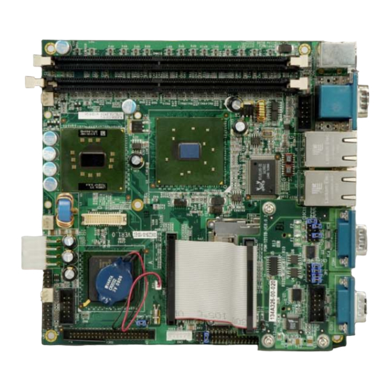
A200C-800Z-R10 Motherboard A200 Motherboard Connectors 1.2.1 A200 Overview The A200 single board computer (SBC) comes with both a motherboard and an expansion daughterboard the POM-121IB. The POM-121IB is mounted on the motherboard, over the PCMCIA flash card slot. The connectors on both these boards are described completely below. - Page 18 CKY-6614 WSB- Card 2 x RS-232 serial port connector 1 x Infrared (IrDA) connector 1 x USB 2.0 connector (supports two devices) 1 x CPU cooling fan connector 1 x Audio connector 1 x VGA connector 1 x Power (ATX) connector 1 x Power supply to mainboard connector 1 x LVDS LCD connector 1 x Digitial I/O (DIO) connector...
-
Page 19: Pom-121Ib Connectors
A200C-800Z-R10 Motherboard Figure 1-2: A200 Motherboard Overview (Reverse Side) The A200 motherboard has the following connectors accessible on the reverse side of the A200 (see Figure 1-2): 1 x Mini PCI slot (on the reverse side) The A200 motherboard has the following connectors on the board rear panel:... -
Page 20: Figure 1-3: Pom-121Ib Overview (Front Side)
CKY-6614 WSB- Card Figure 1-3: POM-121IB Overview (Front Side) The POM-121IB has the following connectors onboard and accessible on the front side of the A200 (see Figure 1-3): 1 x IDE connector 1 x Serial port connector (COM3) The POM-121IB has six jumpers (JP1 – JP6) accessible on the front side (see Figure 1-3). These jumpers are used to set the serial port mode for COM3 and COM4. -
Page 21: Rear Panel Interfaces
A200C-800Z-R10 Motherboard Figure 1-4: Expansion Daughter Board Overview (Reverse Side) The POM-121IB has the following connectors accessible on the reverse side (see Figure 1-4): 1 x Mini PCI slot (on the reverse side) The location of these connectors on the POM-121IB can be seen in Figure 1-3. These connectors are fully described in Chapter 3. -
Page 22: Technical Specifications
CKY-6614 WSB- Card Rear panel interfaces are listed below: 1 x PCMCIA slot 1 x compact flash slot 3 x Serial port slots (COM1, COM3, and COM4) 2 x LAN RJ-45 connectors (LAN1 and LAN 2) 4 x USB 2.0 ports 1 x VGA connector 1 x PS/2 keyboard connector 1 x PS/2 mouse connector... -
Page 23: Pom-121Ib Expansion Daughterboard Technical Specifications
A200C-800Z-R10 Motherboard USB2.0 6x USB 2.0, 4 in rear, 2 by pin header 2x IDE KB/MS PSII Mini DIMM Software programmable 1-255 sec. by supper I/O By super I/O IrDA 4 input / 4 output by supper I/O Digital I/O... - Page 24 CKY-6614 WSB- Card THIS PAGE IS INTENTIONALLY LEFT BLANK ® Technology, Corp. 1-24...
-
Page 25: Detailed Specifications
A200C-800Z-R10 Motherboard Chapter Detailed Specifications 1-25... -
Page 26: Cpu Support
CKY-6614 WSB- Card CPU Support The A200 board comes with a preinstalled ultra low voltage (ULV) Intel® Celeron® M 800MHz zero cache processor. The 800MHz Intel® Celeron® M processor has the following features and specifications: Operates at 1.004 volts Thermal design power (TDP) of 7 watts 400 MHz system bus Advanced mobile power management, including Deep Sleep states, helps enable longer battery life by minimizing the power consumption of the processor during brief periods of... -
Page 27: Intel® Ich4 Southbridge Chipset
A200C-800Z-R10 Motherboard quality and full surround-sound capability. LAN Connect Interface (LCI) provides flexible network solutions such as 10/100 Mbps Ethernet and 10/100 Mbps Ethernet with LAN manageability Dual Ultra ATA/100 controllers, coupled with the Intel® Application Accelerator supports faster IDE transfers to storage devices... -
Page 28: Graphics Support
CKY-6614 WSB- Card Figure 2-1: Data Flow Block Diagram Graphics Support The Intel® is integrated on the Intel® 852GM Northbridge chipset. The Extreme Graphics 2 Intel® Extreme Graphics 2 features are listed below. Enhanced Rapid Pixel and Texel Rendering: Optimized visual quality and performance from the addition of hardware to support of texel formatting, bicubic filter, color blending accuracy, and video mixing render, resulting in optimized visual quality and performance. - Page 29 A200C-800Z-R10 Motherboard arbitration between CPU, system memory and graphics memory. Intel® Extreme Graphics 2 specifications are listed below: Enhanced 2D: 256-bit internal path 8/16/32bpp DirectDraw*, GDI, GDI+ Anti-aliased text support Alpha blending Alphas stretch blitter Hardware alpha blended RGB cursor...
-
Page 30: Memory Support
CKY-6614 WSB- Card 350MHz RAMDAC for up to QXGA analog monitor support Dual DVO ports for up to QXGA digital display support Multiple display types (LVDS, DVI, TV-out, CRT) Memory Support The A200 CPU has two 240-pin dual inline memory module (DIMM) sockets and supports up to two 266MHz DDR DIMM modules with a maximum RAM of 2GB (1GB module in each slot). -
Page 31: Drive Interfaces
A200C-800Z-R10 Motherboard Fully compliant with IEEE 802.3, IEEE 802.3u, IEEE 802.3ab Supports IEEE 802.1P Layer 2 Priority Encoding Supports IEEE 802.1Q VLAN tagging Serial EEPROM 3.3V signaling, 5V PCI I/O tolerant Transmit/Receive FIFO (8K/64K) support Supports power down/link down power saving... -
Page 32: Real Time Clock
CKY-6614 WSB- Card 2.10 Real Time Clock 256-byte battery backed CMOS RAM 2.11 System Monitoring The A200 motherboard is capable of self-monitoring various aspects of its operating status including: CPU, chipset, and battery voltage, +3.3V, +5V, and +12V RPM of cooling fans CPU and board temperatures (by the corresponding embedded sensors) 2.12 Infrared Data Association (IrDA) Interface The A200 Motherboard IrDA supports the following interfaces. -
Page 33: Operating Temperature And Temperature Control
A200C-800Z-R10 Motherboard 2.15 Operating Temperature and Temperature Control The maximum and minimum operating temperatures for the A200 Motherboard are listed below. Minimum Operating Temperature: 0ºC (32°F) Maximum Operating Temperature: 60°C (140°F) A cooling fan and heat sink must be installed on the CPU. Thermal paste must be smeared on the lower side of the heat sink before it is mounted on the CPU. -
Page 34: Power Consumption
CKY-6614 WSB- Card LFE output Built-in 50mW/20ohm amplifier for both Front-out and Surround-Out External Amplifier Power Down (EAPD) capability Power management and enhanced power saving features Supports Power-Off CD function Adjustable VREFOUT control Supports 48KHz S/PDIF output, complying with AC'97 Rev 2.3 specifications Supports 32K/44.1K/48KHz S/PDIF input Power support: Digital: 3.3V;... -
Page 35: Packaged Contents And Optional Accessory Items
A200C-800Z-R10 Motherboard 2.18 Packaged Contents and Optional Accessory Items 2.18.1 Package Contents When you unpack the A200 Motherboard you should find the following components. 1x A200 single board computer 1x mini jumper pack (P/N: 33100-000079-RS) 1x ATA33 HDD cable (P/N:32200-000009-RS) - Page 36 CKY-6614 WSB- Card THIS PAGE IS INTENTIONALLY LEFT BLANK ® Technology, Corp. 1-36...
-
Page 37: Connectors And Jumpers
A200C-800Z-R10 Motherboard Chapter Connectors and Jumpers 1-37... -
Page 38: Peripheral Interface Connectors
CKY-6614 WSB- Card Peripheral Interface Connectors The locations of and list of all peripheral interface connectors are shown in Section 3.1.1. 3.1.1 A200 Peripheral Interface Connectors Figure 3-1 and Figure 3-2 shows the onboard peripheral connectors, backplane peripheral connectors and onboard jumpers. Figure 3-1: A200 Connector and Jumper Locations (Front Side) ®... -
Page 39: Figure 3-2: A200 Connector And Jumper Locations (Reverse Side)
A200C-800Z-R10 Motherboard Figure 3-2: A200 Connector and Jumper Locations (Reverse Side) Table 3-1 shows a list of the peripheral interface connectors on the A200 motherboard. Detailed descriptions of these connectors can be found in Section 3.2 on page 43. Label... -
Page 40: Pom-121Ib Peripheral Interface Connectors
CKY-6614 WSB- Card LPT1 Parallel port connector 26-pin header AUDIO Audio connector 16-pin header VGA connector 10-pin header Power connector 8-pin header ATXCTL Power supply to mainboard connector 3-pin header LVDS LCD connector 30-pin header Digital I/O connector 10-pin header Front panel connector 12-pin header Power out connector... -
Page 41: Figure 3-3: Pom-121Ib Jumper And Connector Locations (Front Side)
A200C-800Z-R10 Motherboard Figure 3-3: POM-121IB Jumper and Connector Locations (front side) Figure 3-4: POM-121IB Jumper and Connector Locations (Reverse Side) Table 3-2 shows a list of the peripheral interface connectors on the POM-121IB. Detailed descriptions of these connectors can be found in Section 3.2 on page 43. -
Page 42: Rear Panel Connectors
CKY-6614 WSB- Card 3.1.3 Rear Panel Connectors Figure 3-1 and Figure 3-3 show the rear panel connectors on the A200 motherboard. Detailed descriptions of these connectors can be found in Section 3.3. Label Connector Type Ethernet connector RJ-45 connector Two USB 2.0 ports USB port connectors Ethernet connector RJ-45 connector... -
Page 43: Internal Peripheral Connectors
A200C-800Z-R10 Motherboard JP2 (POM-121IB) COM3 Port RI and Voltage Selection 3-pin header JP3 (POM-121IB) COM3 Port RI and Voltage Selection 3-pin header JP4 (POM-121IB) COM4 pin-9 as signal RI or voltage 3-pin header JP5 (POM-121IB) COM4 pin-9 as signal RI or voltage... -
Page 44: Figure 3-5: A200 Ide Device Connector Locations
CKY-6614 WSB- Card Figure 3-5: A200 IDE Device Connector Locations Figure 3-6: POM-121IB IDE Device Connector Location DESCRIPTION DESCRIPTION RESET# DATA 7 DATA 8 DATA 6 DATA 9 DATA 5 DATA 10 DATA 4 DATA 11 DATA 3 DATA 12 DATA 2 DATA 13 DATA 1... -
Page 45: Com2 Serial Port Connector
A200C-800Z-R10 Motherboard DATA 0 DATA 15 IOW# IOR# CHRDY REV. PULL LOW DACK GROUND-DEFAULT INTERRUPT HDC CS0# HDC CS1# HDD ACTIVE# +5V(IDE2 only) +5V(IDE2 only) GND(IDE2 only) N/C(IDE2 only) Table 3-5: IDE Device Connector Pinouts 3.2.2 COM2 Serial Port Connector... -
Page 46: Figure 3-7: A200 Com2 Port Location
CKY-6614 WSB- Card Figure 3-7: A200 COM2 Port Location Figure 3-8: POM-121IB COM3 Port Location NOTE: Pin 10 in the 10-pin serial connector (COM3) on the POM-121IB does not have a connection. The RI (ring indicator) pin, Pin-8 can be set to provide 5V or 12V of power using the jumper settings to provide power to serial communication devices. -
Page 47: Infrared (Irda) Interface Connector
A200C-800Z-R10 Motherboard DESCRIPTION DESCRIPTION Table 3-6: COM Serial Port Connector Pinouts 3.2.3 Infrared (IrDA) Interface Connector CN Label: CN Type: 1 x 5 pin header CN Location: See Figure 3-9 CN Pinouts: See Table 3-7 The integrated infrared (IrDA) connector supports both Serial Infrared (SIR) and Amplitude Shift Key Infrared (ASKIR) interfaces. -
Page 48: Internal Usb Connector
CKY-6614 WSB- Card DESCRIPTION IR-RX IR-TX Table 3-7: IR Interface Connector Pinouts 3.2.4 Internal USB Connector CN Label: CN Type: 2x4 pin header CN Location: See Figure 3-10 CN Pinouts: See Table 3-8 One onboard 2x4 pin USB connector can connect to two USB 2.0 devices. Four additional USB ports are found on the rear panel. -
Page 49: Cpu Cooling Fan Connector
A200C-800Z-R10 Motherboard Figure 3-10: USB Port Connector Location DESCRIPTION DESCRIPTION DATA0- DATA1+ DATA0+ DATA1- Table 3-8: USB Connector Pinouts 3.2.5 CPU Cooling Fan Connector CN Label: CPU_FAN CN Type: 1x3 pin header CN Location: See Figure 3-11 CN Pinouts: See Table 3-9... -
Page 50: Figure 3-11: Cpu Cooling Fan Connector Location
CKY-6614 WSB- Card The CPU cooling fan connector (CPU_FAN) provides a 12V, 500mA current to the cooling fan. The connector has a "rotation" pin to get rotation signals from fans and notify the system so the system BIOS can recognize the fan speed. Please note that only certain fans can issue the rotation signals. -
Page 51: Audio Connector
A200C-800Z-R10 Motherboard 3.2.6 Audio Connector CN Label: AUDIO CN Type: 2 x 8 pin header CN Location: See Figure 3-12 CN Pinouts: See Table 3-10 The onboard audio connector (AUDIO) is directly connected to an onboard AC’97 AUDIO CODEC (RTL8119S-32). The audio connector directly connects to the MIC-IN, CD-IN and LINE-IN. -
Page 52: Vga Connector
CKY-6614 WSB- Card LINE_IN_R LINE_IN_L MIC_IN Table 3-10: Audio Connector Pinouts 3.2.7 VGA Connector CN Label: CN Type: 2x5 pin header CN Location: See Figure 3-13 CN Pinouts: See Table 3-11 The 2 x 5 pin VGA connector connects to a standard 10-pin female VGA connector. This can in turn be connected to an external graphics device. -
Page 53: Power Connector
A200C-800Z-R10 Motherboard DESCRIPTION DESCRIPTION DDC_DATA GREEN DDC_CLOCK BLUE HSYNC VSVNC Table 3-11: VGA Connector Pinouts 3.2.8 Power Connector CN Label: CN Type: 2x4 pin header CN Location: See Figure 3-14 CN Pinouts: See Table 3-12 The power connector (PW) is connected to an independent power supply unit (PSU) that supplies power to the system. -
Page 54: Atxctl Connector
CKY-6614 WSB- Card DESCRIPTION DESCRIPTION +12V +12V -12V Table 3-12: Power Connector Pinouts 3.2.9 ATXCTL Connector CN Label: ATXCTL CN Type: 1x3 pin header CN Location: See Figure 3-15 CN Pinouts: See Table 3-13 The ATXCTL connector connects the power supply to the motherboard connector. The power supply unit with the ATX connector is connected through the power button and the 5VSB. -
Page 55: Lvds Lcd Connector
A200C-800Z-R10 Motherboard DESCRIPTION 5VSB PS-ON Table 3-13: ATXCTL Connector Pinouts 3.2.10 LVDS LCD Connector CN Label: CN Type: 2x15 pin header CN Location: See Figure 3-16 CN Pinouts: See Table 3-14 The LVDS LCD connector (CN8) connects to a one or two channel (18-bit or 36-bit) LVDS panel. -
Page 56: Digital I/O Connector
CKY-6614 WSB- Card DESCRIPTION DESCRIPTION LVDS data0 output + LVDS data0 output - LVDS data1 output + LVDS data1 output - LVDS data2 output + LVDS data2 output - LVDS clock output + LVDS clock output - LVDS data3 output + LVDS data3 output - LVDS data0 output + LVDS data0 output -... -
Page 57: Front Panel Connector
A200C-800Z-R10 Motherboard Figure 3-17: DIO Connector Location DESCRIPTION DESCRIPTION INPUT1 OUTPUT1 INPUT2 OUTPUT2 INPUT3 OUTPUT3 INPUT4 OUTPUT4 Table 3-15: DIO Connector Pinouts 3.2.12 Front Panel Connector CN Label: CN Type: 2x5 pin header CN Location: See Figure 3-18 CN Pinouts:... -
Page 58: Figure 3-18: Front Panel Connector Location
CKY-6614 WSB- Card Power button Reset button Speaker Power LED HDD LED Figure 3-18: Front Panel Connector Location DESCRIPTION DESCRIPTION POWER LED+ Speaker+ POWER LED- PWR BUTTON- PWR BUTTON+ Speaker - HDD LED+ RESET+ HDD LED+ RESET- Table 3-16: Front Panel Connector Pinouts ®... -
Page 59: Power Out Connector
A200C-800Z-R10 Motherboard 3.2.13 Power Out Connector CN Label: CN Type: 1x3 pin header CN Location: See Figure 3-19 CN Pinouts: See Table 3-17 The power out connector (CN2) provides power for extension use. Figure 3-19: Power Extension Connector Location DESCRIPTION... -
Page 60: Lcd Backlight Connector
CKY-6614 WSB- Card HDD LED+ RESET+ HDD LED+ RESET- Table 3-17: Power Extension Connector (CN2) Pinouts 3.2.14 LCD Backlight Connector CN Label: CN Type: 1x6 pin header CN Location: See Figure 3-20 CN Pinouts: See Table 3-18 The LCD backlight connector (CN3) connects to the backlight in an LCD screen. Figure 3-20: LCD Backlight Connector Location DESCRIPTION DESCRIPTION... -
Page 61: External (Rear Panel) Connectors
A200C-800Z-R10 Motherboard Table 3-18: LCD Backlight Connector Pinouts External (Rear Panel) Connectors Figure 3-21 shows the A200 Motherboard rear panel. The peripheral connectors on the back panel can be connected to devices externally when the CPU card is installed in a chassis. -
Page 62: Keyboard/Mouse Connector
CKY-6614 WSB- Card 3.3.1 Keyboard/Mouse Connector CN Label: KB_MS CN Type: Dual PS/2 CN Location: See Figure 3-21 (labeled number 1 and 2) CN Pinouts: See Figure 3-22 and Table 3-19 The A200 keyboard and mouse connectors are standard PS/2 connectors. Figure 3-22: Dual PS/2 Pinouts and Configuration DESCRIPTION DESCRIPTION... -
Page 63: Serial Port And Vga Connector
A200C-800Z-R10 Motherboard KB_CLOCK MS_CLOCK Table 3-19: PS/2 Connector Pinouts 3.3.2 Serial Port and VGA connector CN Label: CRT_COM1 CN Type: 15-pin Female (VGA) and 9-Pin Male (COM1) CN Location: See Figure 3-21 (LAN labeled number 5 and 6) CN Pinouts: See Figure 3-23, Table 3-20 (VGA) and Table 3-21 (COM1) The A200 offers two high speed NS16C550 compatible UART’s with 16-byte... -
Page 64: Lan And Usb Connectors
CKY-6614 WSB- Card DDC DAT HSYNC VSYNC DDCCLK Table 3-20: VGA Connector Pinouts DESCRIPTION DESCRIPTION Table 3-21: Serial Port (COM1) Connector Pinouts 3.3.3 LAN and USB Connectors CN Label: J1 and J2 CN Type: RJ-45 (LAN) and USB ports (USB) CN Location: See Figure 3-21 (LAN labeled number 5 and 6, USB labeled 7 and 8) -
Page 65: Figure 3-24: Rj-45 And Dual Usb Connectors
A200C-800Z-R10 Motherboard Figure 3-24: RJ-45 and Dual USB Connectors The pin assignments are listed in the following tables: DESCRIPTION DESCRIPTION +2.5VCC TX0+ TX0- TX1+ TX1- TX2+ TX2- TX3+ TX3- LINK- LINK+ ACTIVE- ACTIVE+ Table 3-22: LAN Pinouts DESCRIPTION DESCRIPTION DATA-... -
Page 66: Serial Port Connectors
CKY-6614 WSB- Card The RJ-45 Ethernet connector has two status LEDs, one green and one yellow. The green LED indicates activity on the port and the yellow LED indicates the port is linked. See Table 3-24. DESCRIPTION STATUS DESCRIPTION STATUS GREEN Activity YELLOW... -
Page 67: Serial Port Connectors
A200C-800Z-R10 Motherboard COM3 pinouts are shown below. Description Description DCD3 DSR3 RXD3 RTS3 TXD3 CTS3 DTR3 RI3 (or 5V/12V) GROUND Table 3-25: COM3 Pinouts (RS-232 mode) COM4 pinouts when COM4 is operating in RS-232 mode are shown below. Description Description... -
Page 68: Onboard Jumpers
CKY-6614 WSB- Card CN Location: See Figure 3-21 (labeled number 11 and 12) A PCMCIA slot (on the A200 mother board) and a CF slot (on the bottom side of the POM-121IB) are accessible on the rear panel. The PCMCIA slot supports standard PCMCIA memory cards . -
Page 69: Lvds Panel Voltage Selection Jumper
A200C-800Z-R10 Motherboard Label (location) Connector Type CLR_CMOS (A200) Clear CMOS 3-pin header JP1 (A200) LVDS LCD voltage setting 6-pin header JP1 (POM-121IB) COM4 mode selection 12-pin header JP2 (POM-121IB) COM3 Port RI and Voltage Selection 3-pin header JP3 (POM-121IB) COM3 Port RI and Voltage Selection... -
Page 70: Reset Cmos Jumper
CKY-6614 WSB- Card Figure 3-28: JP1 Pinout Locations 3.4.2 Reset CMOS Jumper Jumper Label: Jumper Type: 3 pin header Jumper Settings: See Table 3-30 Jumper Location: See Figure 3-29 If the CPU Card fails to boot due to improper BIOS setting, use this jumper to clear the CMOS data and reset the system BIOS information. -
Page 71: Com4 Mode Selection Jumpers
A200C-800Z-R10 Motherboard Load Optimal Defaults Load Failsafe Defaults. After you have done one of the above, save your changes and exit the CMOS Setup menu. CLR_CMOS DESCRIPTION 1-2 (Default) Keep CMOS Setup Clear CMOS Setup Table 3-30: CLR_CMOS Jumper Settings The clear CMOS jumper is located in Figure 3-29. -
Page 72: Com4 In Rs-232 Mode
CKY-6614 WSB- Card Jumper Settings: See Section 3.4.3.1 and Section 3.4.3.2 Jumper Location: See Figure 3-30 JP1 and JP4 on the POM-121B allow you to specify the COM4 mode as either RS-232 or RS-422/452. The jumper locations and their pinouts locations are shown in Figure 3-30 below. -
Page 73: Com4 In Rs-422/452 Mode
A200C-800Z-R10 Motherboard 3.4.3.2 COM4 in RS-422/452 Mode To operate COM4 in RS-422/452 mode, the following jumper settings must be made: JP1: For COM4 to operate in RS-432/452 mode, short the following pins Pin 2 and Pin 3 Pin 5 and Pin 6... -
Page 74: Setting Com3 Pin 9 (Ri Or Voltage)
CKY-6614 WSB- Card 3.4.4.1 Setting COM3 Pin 9 (RI or Voltage) Figure 3-31: COM3 RI Pin Selection Pinout Locations For the RI pin on COM3 to retain its RI functionality make the following settings: JP3: RI pin retains RI functionality (Default), short the following pins Pin 2 and Pin 3 JP2: If RI pin retains RI functionality, the setting on this jumper is not important... -
Page 75: Setting Com4 Pin 9 (Ri Or Voltage)
A200C-800Z-R10 Motherboard 3.4.4.2 Setting COM4 Pin 9 (RI or Voltage) Figure 3-32: COM4RI Pin Selection Pinout Locations For the RI pin on COM$ to retain its RI functionality make the following settings: JP5: RI pin retains RI functionality (Default), short the following pins... - Page 76 CKY-6614 WSB- Card THIS PAGE IS INTENTIONALLY LEFT BLANK ® Technology, Corp. 1-76...
-
Page 77: Installation And Configuration
A200C-800Z-R10 Motherboard Chapter Installation and Configuration 1-77... -
Page 78: Installation Considerations
CKY-6614 WSB- Card Installation Considerations NOTE: The following installation notices and installation considerations should be read and understood before the CPU card is installed. All installation notices pertaining to the installation of the CPU card should be strictly adhered to. Failing to adhere to these precautions may lead to severe damage of the CPU card and injury to the person installing the CPU card. -
Page 79: Unpacking
A200C-800Z-R10 Motherboard are properly connected. allow screws to come in contact with the PCB circuit, connector pins, or its components. Unpacking NOTE: If any of the items listed below are missing when you unpack the A200 CPU card, do not proceed with the installation and contact the reseller or vendor you purchased the CPU card from. -
Page 80: A200 Motherboard Installation
A200 Motherboard Installation WARNING! Never run the A200 without an appropriate heatsink and cooler that can be ordered from IEI Technology or purchased separately. WARNING! Please note that the installation instructions described in this manual should be carefully followed in order to avoid damage to the A200 components and injury to you. -
Page 81: Components To Install
A200C-800Z-R10 Motherboard 4.3.2 Components to Install To install the A200, the following components must be installed or connected to the A200 DIMM modules Peripheral devices 4.3.3 DIMM Module Installation 4.3.3.1 Purchasing the Memory Module When you purchase your DIMM modules, the following considerations should be taken... -
Page 82: Ide Disk Drive Connector (Ide1)
CKY-6614 WSB- Card Quantity Type mini jumper pack ATA33 HDD cable Power cable RS-232 cable Table 4-1: IEI Provided Cables 4.3.4.1 IDE Disk Drive Connector (IDE1) The cable used to connect the A200 to the IDE HDD is a standard 44-pin ATA33 flat cable. To connect an IDE device to the A200 follow the instructions below. -
Page 83: Chassis Installation
A200C-800Z-R10 Motherboard motherboard. Step 2: Connect the other end of the same ribbon cable in Step 1 to the IDE1 connector on the expansion daughterboard. Step 0: Chassis Installation After the DIMM modules have been installed and after the internal peripheral connectors have been connected to the peripheral devices and the jumpers have been configured, the A200 can be mounted into chassis. - Page 84 CKY-6614 WSB- Card THIS PAGE IS INTENTIONALLY LEFT BLANK ® Technology, Corp. 1-84...
-
Page 85: Ami Bios Setup
A200C-800Z-R10 Motherboard Chapter AMI BIOS Setup 1-85... -
Page 86: Introduction
CKY-6614 WSB- Card Introduction A licensed copy of AMI BIOS is preprogrammed into the ROM BIOS. The BIOS setup program allows users to modify the basic system configuration. This chapter describes how to access the BIOS setup program and the configuration options you may change. 5.1.1 Starting Setup The AMI BIOS is activated when you turn on the computer. -
Page 87: Getting Help
A200C-800Z-R10 Motherboard F2 /F3 key Change color from total 16 colors. F2 to select color forward. F10 key Save all the CMOS changes, only for Main Menu Table 5-1: BIOS Navigation Keys 5.1.3 Getting Help When you press F1 a small help window describing the appropriate keys to use and the possible selections for the highlighted item appears. -
Page 88: Main
CKY-6614 WSB- Card Main When you enter the BIOS Setup program, the Main menu (BIOS Menu 1) appears. The Main menu gives you an overview of the basic system information. BIOS Menu 1: Main System Overview The System Overview lists a brief summary of different system components. The fields in System Overview cannot be changed. -
Page 89: Advanced
A200C-800Z-R10 Motherboard Speed: Lists the processor speed Count: The number of CPUs on the A200 System Memory: Displays the auto-detected system memory. Size: Lists memory size The System Overview field also has two user configurable fields: System Time [xx:xx:xx]: Allows you to set the system time. -
Page 90: Cpu Configuration
CKY-6614 WSB- Card BIOS Menu 2: Advanced NOTE: The floppy configuration function shown in the menu above is not available on the A200. 5.3.1 CPU Configuration The CPU Configuration menu (BIOS Menu 3) shows detailed CPU specifications. ® Technology, Corp. 1-90... -
Page 91: Execute Bit Disable
A200C-800Z-R10 Motherboard BIOS Menu 3: CPU Configuration The CPU Configuration menu (BIOS Menu 3) lists the following CPU details: Manufacturer: Lists the name of the CPU manufacturer Brand String: Lists the brand name of the CPU being used Frequency: Lists the CPU processing speed... -
Page 92: Ide Configuration
CKY-6614 WSB- Card Enabled Execution of code in data-only memory pages is EFAULT prohibited. CPU TM Function 5.3.2 IDE Configuration The IDE Configuration menu (BIOS Menu 4) allows you to set or change the configurations for the IDE devices installed in the system. BIOS Menu 4: IDE Configuration OnBoard PCI IDE Controller [Both] The OnBoard PCI IDE Controller BIOS option specifies the IDE channels used by the... -
Page 93: Ide Master And Ide Slave
A200C-800Z-R10 Motherboard Disabled Prevents the system from using the onboard IDE controller Only allows the system to detect the Primary IDE Primary channel, including both the Primary Master and Primary Slave) Only allows the system to detect the Secondary IDE... -
Page 94: Ide Master, Ide Slave
CKY-6614 WSB- Card 5.3.2.1 IDE Master, IDE Slave IDE Master and IDE Slave configuration options for both primary and secondary IDE devices are shown in the BIOS menu below. BIOS Menu 5: IDE Master and IDE Slave Configuration [Advanced/IDE Configuration] Auto-Detected Drive Parameters The “grayed-out”... -
Page 95: Type [Auto]
A200C-800Z-R10 Motherboard method of addressing data on a disk drive is supported or not. Block Mode: Block mode boosts IDE drive performance by increasing the amount of data transferred. Only 512 bytes of data can be transferred per interrupt if block mode is not used. Block mode allows transfers of up to 64 KB per interrupt. -
Page 96: Lba/Large Mode [Auto]
CKY-6614 WSB- Card LBA/Large Mode [Auto] The LBA/Large Mode BIOS option allows you to disable or auto detect LBA (Logical Block Addressing). LBA is a method of addressing data on a disk drive. In LBA mode, the maximum drive capacity is 137 GB. Disabled This selection prevents the BIOS from using the LBA mode control on the specified channel. -
Page 97: Dma Mode [Auto]
A200C-800Z-R10 Motherboard PIO mode 2 selected with a maximum transfer rate of 8.3MBps PIO mode 3 selected with a maximum transfer rate of 11.1MBps PIO mode 4 selected with a maximum transfer rate of 16.6MBps (This setting generally works with all hard disk drives manufactured after 1999. -
Page 98: Super Io Configuration
CKY-6614 WSB- Card Enabled (Default) Allows BIOS to use 32-bit data transfers on support hard disk drives. 5.3.3 Super IO Configuration The Super IO Configuration menu (BIOS Menu 6) allows you to set or change the configurations for the parallel ports and serial ports. BIOS Menu 6: Super IO Configuration Serial Port1 Address [3F8/IRQ4] The Serial Port1 Address option allows BIOS to select the Serial Port 1 base address. -
Page 99: Serial Port2 Address [2F8/Irq3]
A200C-800Z-R10 Motherboard 3E8/IRQ4 Serial Port 1 I/O port address is 3E8 and the interrupt address is IRQ4 Serial Port 1 I/O port address is 2E8 and the interrupt 2E8/IRQ3 address is IRQ3 Serial Port2 Address [2F8/IRQ3] The Serial Port2 Address option allows BIOS to select the Serial Port 2 base address. -
Page 100: Hardware Health Configuration
CKY-6614 WSB- Card Serial Port 3 base address is 2F0 Serial Port 3 base address is 2E0 Serial Port3 IRQ [11] The Serial Port3 IRQ selection allows you to set the serial port 3 interrupt address 10 is assigned as the serial port 3 interrupt address 11 is assigned as the serial port 3 interrupt address EFAULT Serial Port4 Address [2E8]... -
Page 101: Menu 7: Hardware Health Configuration
A200C-800Z-R10 Motherboard BIOS Menu 7: Hardware Health Configuration The following hardware health parameters are monitored. System Temperatures: The following system temperatures are monitored CPU Temperature System Temperature Sensor 1 System Temperature Sensor 2 CPU Fan Speed Voltages: The following system voltages are monitored CPU Core +3.30Vin... -
Page 102: Acpi Configuration
CKY-6614 WSB- Card 5VSB VBAT 5.3.5 ACPI Configuration The ACPI Configuration menu (BIOS Menu 8) allows you to configure the Advanced Configuration and Power Interface (ACPI) and Power Management (APM) options. BIOS Menu 8: ACPI Configuration ACPI Aware O/S [Yes] ACPI Aware O/S can only be configured if your OS complies with the ACPI standard. -
Page 103: Mps Configuration
A200C-800Z-R10 Motherboard (Default) Enables the ACPI support for the operating system. This selection should be enabled if the OS does support ACPI 5.3.6 MPS Configuration The MPS Configuration menu (BIOS Menu 9) allows you to configure the multi-processor table. BIOS Menu 9: MPS Configuration MPS Revision [1.1]... -
Page 104: Usb Configuration
CKY-6614 WSB- Card 5.3.7 USB Configuration The USB Configuration menu (BIOS Menu 10) gives you information on the USB configuration and allows you to configure some USB features. BIOS Menu 10: USB Configuration USB Configuration The USB Configuration field shows the system USB configuration. The items listed are: Module Version: x.xxxxx.xxxxx USB Devices Enabled: Lists the USB devices that are enabled on the system. -
Page 105: Legacy Usb Support [Disabled]
A200C-800Z-R10 Motherboard Disabled USB function disabled Enabled (Default) USB function enabled Legacy USB Support [Disabled] The Legacy USB Support BIOS option refers to USB mouse and USB keyboard support. Normally if this option is not enabled, any attached USB mouse or USB keyboard does not become available until a USB compatible operating system is fully booted with all USB drivers loaded. -
Page 106: Usb Mass Storage Delay [20 Sec]
CKY-6614 WSB- Card The USB Mass Storage Device Configuration field appears if a USB drive is connected to one of the USB ports or connectors. If this option is selected a menu appears. BIOS Menu 11: USB Mass Storage Device USB Mass Storage Delay [20 sec] The USB Mass Storage Delay BIOS option allows you to set number of seconds the POST waits for the USB mass storage device after the start unit command is issued. -
Page 107: Boot
A200C-800Z-R10 Motherboard Boot The Boot menu (BIOS Menu 12) allows you to configure system boot options. BIOS Menu 12: Boot 1-10... -
Page 108: Boot Settings Configuration
CKY-6614 WSB- Card 5.4.1 Boot Settings Configuration The Boot Settings Configuration menu (BIOS Menu 12) allows you to configure advanced system boot options. BIOS Menu 13: Boot Settings Configuration Quick Boot [Enabled] The Quick Boot BIOS option allows you to make the computer speed up the boot process. -
Page 109: Quiet Boot [Disabled]
A200C-800Z-R10 Motherboard Quiet Boot [Disabled] The Quiet Boot BIOS option allows the boot up screen options to be modified between POST messages or an OEM logo. Disabled (Default) Displays normal POST messages Enabled Displays OEM Logo instead of POST messages... -
Page 110: Wait For 'F1' If Error [Enabled]
CKY-6614 WSB- Card mouse is being used. Wait For ‘F1’ If Error [Enabled] The Wait For ‘F1’ if Error option allows you to specify how the system responds when the system detects an error on boot up. Disabled If there is an error when booting up, the system does not wait for user intervention but continues to boot up in the operating system. -
Page 111: Boot Device Priority
A200C-800Z-R10 Motherboard Enabled (Default) Can be booted from a remote system through the 5.4.2 Boot Device Priority The Boot Device Priority menu (BIOS Menu 14) specifies the boot sequence from the available devices. Possible boot devices may include: CD/DVD BIOS Menu 14: Boot Device Priority Settings... -
Page 112: Hard Disk Drives
CKY-6614 WSB- Card 5.4.3 Hard Disk Drives The Hard Disk Drives menu is similar to the Removable Drives BIOS Menu 15 and it specifies the boot sequence of the available HDDs. When the menu is opened, the HDDs connected to the system are listed as shown below: 1st Drive [HDD: PM-(part number)] 2nd Drive [HDD: PS-(part number)]... -
Page 113: Menu 15: Removable Drives
A200C-800Z-R10 Motherboard You can then select the boot sequence from the available devices. If you select the “1st Drive” option a list of available removable drives are shown. Select the first removable drive you wish the system to boot from. If you do not wish to boot from the “1st Drive” you may also disable it. -
Page 114: Cd/Dvd Drives
CKY-6614 WSB- Card 5.4.5 CD/DVD Drives The CD/DVD Drives menu is similar to the Removable Drives BIOS Menu 15 and it specifies the boot sequence of the available CD/DVD drives. When the menu is opened, the CD drives and DVD drives connected to the system are listed as shown below: 1st Drive [CD/DVD: PM-(part ID)] 2nd Drive [HDD: PS-(part ID)]... -
Page 115: Change Supervisor Password
A200C-800Z-R10 Motherboard BIOS Menu 16: Security Change Supervisor Password The default setting for the Change Supervisor Password is Not Installed. If you wish to install a supervisor password, select this field and enter the password. After the password has been added, a User Access Level option and a Password Check option appear. -
Page 116: Chipset
CKY-6614 WSB- Card Change User Password The default setting for the Change User Password is Not Installed. If you wish to install a user password, select this field and enter the password. After the password has been added, Install appears next to Change User Password. Password Check [Setup] The Password Check option allows you to specify when a user is prompted for the password. -
Page 117: Northbridge Configuration
A200C-800Z-R10 Motherboard BIOS Menu 17: Chipset 5.6.1 Northbridge Configuration The Northbridge Configuration menu (BIOS Menu 17) allows you to configure the Northbridge chipset. 1-11... -
Page 118: Dram Frequency [200]
CKY-6614 WSB- Card BIOS Menu 18:Northbridge Chipset Configuration [Chipset] DRAM Frequency [200] The DRAM Frequency option allows you to specify the DRAM frequency or allow the system to automatically detect the DRAM frequency. 200MHz Sets the DRAM frequency to 200MHz 266MHz Sets the DRAM frequency to 266MHz Sets the DRAM frequency to 333MHz... -
Page 119: Dram Cas# Latency [2.5]
A200C-800Z-R10 Motherboard EEPROM contains all necessary DIMM specifications the including speed of the individual components such as CAS and bank cycle time as well as valid settings for the module and the manufacturer's code. The SPD enables the BIOS to read the spec sheet of the DIMMs on boot-up and then adjust the memory timing parameters accordingly. -
Page 120: Dram Ras# To Cas# Delay [3 Clocks]
CKY-6614 WSB- Card 3 clocks (D EFAULT DRAM RAS# to CAS# Delay [3 clocks] The DRAM RAS# to CAS# Delay refers to the Row Address Strobe (RAS) to CAS delay time. (To be able to change this configuration option the DRAM Latency Timing configuration option must be set to “Manual”) The following configuration options are available 2 clocks... -
Page 121: Init. Graphic Adapter Priority [Internal Vga]
A200C-800Z-R10 Motherboard Enabled Memory is reserved for ISA expansion cards Init. Graphic Adapter Priority [Internal VGA] The Init. Graphic Adapter Priority option allows you to select the graphics controller the system uses as a primary boot device. The options are:... -
Page 122: Boot Display Device [Crt]
CKY-6614 WSB- Card Boot Display Device [CRT] The Boot Display Device BIOS option allows you to select the display device the system uses when it boots. The available options are listed below: Auto CRT (Default) CRT + EFP CRT + LFP Flat Panel Type [640x480 18bit LVDS] The Flat Panel Type BIOS option allows you to specify the flat panel PC type you are using. -
Page 123: Southbridge Configuration
A200C-800Z-R10 Motherboard 5.6.2 SouthBridge Configuration The SouthBridge Configuration menu (BIOS Menu 19) allows you to configure the southbridge chipset. BIOS Menu 19:SouthBridge Chipset Configuration [Chipset] OnBoard AC97 The OnBoard AC97 Audio option allows you to enable or disable the AC’97 CODEC. -
Page 124: Power
CKY-6614 WSB- Card The OnBoard LAN1 option allows you to enable or disable the onboard LAN1. Disabled Onboard LAN1 device manually disabled Enabled (Default) The onboard LAN1 device automatically detected and enabled OnBoard LAN2 [Enabled] The OnBoard LAN2 option allows you to enable or disable the onboard LAN1. Disabled Onboard LAN2 device manually disabled Enabled... -
Page 125: Power Management/Apm [Enabled]
A200C-800Z-R10 Motherboard Power Management/APM [Enabled] The Power Management/APM BIOS option allows you to access the advanced power management features. Disabled Disables the Advanced Power Management (APM) feature Enabled (Default) Enables the APM feature Power Button Mode [On/Off] The Power Button Mode BIOS option allows you to specify how the power button functions. -
Page 126: Resume On Ring [Disabled]
CKY-6614 WSB- Card Resume on Ring [Disabled] The Resume on Ring BIOS option allows you to specify if the system will be roused from a suspended or standby state when there is activity on the RI (ring in) modem line. That is, the system will be roused by an incoming call on a modem. -
Page 127: Exit
A200C-800Z-R10 Motherboard Exit The Exit menu (BIOS Menu 21) allows you to load default BIOS values, optimal failsafe values and to save configuration changes. BIOS Menu 21:Exit Save Changes and Exit If you have finished making the configuration changes and wish to save them and exit the BIOS menus, select this option. -
Page 128: Discard Changes
CKY-6614 WSB- Card Discard Changes If you have finished making configuration changes but do not want to save them but still want to continue working with BIOS, select this option. Load Optimal Defaults This option allows you to load optimal default values for each of the parameters on the Setup menus. -
Page 129: Software Drivers
A200C-800Z-R10 Motherboard Chapter Software Drivers 1-12... -
Page 130: Available Software Drivers
CKY-6614 WSB- Card Available Software Drivers NOTE: The contents of the CD may vary throughout the life cycle of the product and is subject to change without prior notice. You may visit the IEI website or contact technical support for the latest updates. The A200 board has four software drivers: Chipset Audio... -
Page 131: Figure 6-2: Welcome Screen
A200C-800Z-R10 Motherboard Step 3: The “Welcome” window in Figure 6-2 appears next. Figure 6-2: Welcome Screen Step 4: Click “N ” and the license agreement shown in Figure 6-3 appears. Figure 6-3: License Agreement 1-13... -
Page 132: Figure 6-4: Readme Information
CKY-6614 WSB- Card Step 5: If you agree to the license terms click “Y .” The “Readme” in Figure 6-4 appears. Figure 6-4: Readme Information Step 6: Click “Y .” The driver is installed on the computer. After the installation is complete the installation complete screen shown in Figure 6-5 appears. -
Page 133: Realtek Audio Driver Installation
A200C-800Z-R10 Motherboard Figure 6-5: Restart the Computer RealTek Audio Driver Installation To install the RealTek AC’97 Audio driver, please follow the steps below: Step 1: Insert the CD into the system that contains the A200 board. Open the CD folder and locate the AUDIO DRIVER A3.79 directory. -
Page 134: Figure 6-6: Audio Driver Install Shield Wizard Starting
CKY-6614 WSB- Card Figure 6-6: Audio Driver Install Shield Wizard Starting Step 3: The RealTek Audio Setup prepares the install shield to guide you through the rest of the setup process. See Figure 6-7. Figure 6-7: Audio Driver Setup Preparation Step 4: After install shield is prepared, the welcome screen shown in Figure 6-8 appears. -
Page 135: Figure 6-8: Audio Driver Welcome Screen
A200C-800Z-R10 Motherboard Figure 6-8: Audio Driver Welcome Screen Figure 6-9: Audio Driver Software Configuration Step 5: At this stage the “Digital Signal Not Found” screen shown in Figure 6-10 1-13... -
Page 136: Figure 6-10: Audio Driver Digital Signal
CKY-6614 WSB- Card appears. To continue the installation process, click the “Y ” button. The installation notice shown below appears. Figure 6-10: Audio Driver Digital Signal Step 6: At this stage the clicking the “Y ” button in Figure 6-10 appears, the installation of the driver begins. -
Page 137: Figure 6-11: Audio Driver Installation Begins
A200C-800Z-R10 Motherboard Figure 6-11: Audio Driver Installation Begins Step 7: After the driver installation process is complete, a confirmation screen shown in Figure 6-12 appears 1-13... -
Page 138: Intel Graphics Media Accelerator Driver
CKY-6614 WSB- Card Figure 6-12: Audio Driver Installation Complete Step 8: The confirmation screen shown in Figure 6-12 allows you to restart the computer immediately after the installation is complete or to restart the computer later. For the settings to take effect the computer must be restarted. Once you have decided when to restart the computer, click the “F ”... -
Page 139: Figure 6-13: Gma Driver Installation Welcome Screen
A200C-800Z-R10 Motherboard Figure 6-13: GMA Driver Installation Welcome Screen Step 3: To continue installing click “Next” and a license agreement shown in Figure 6-14 appears. Read through the license agreement. 1-13... -
Page 140: Figure 6-14: Gma Driver License Agreement
CKY-6614 WSB- Card Figure 6-14: GMA Driver License Agreement Step 4: If you choose to accept the terms and conditions stipulated in the license agreement shown Figure 6-14, click the “Y ” button. The installation notice shown in Figure 6-15 appears. Figure 6-15: GMA Driver Installing Notice Step 5: After the driver installation process is complete, a confirmation screen shown in... -
Page 141: Lan Driver Installation
A200C-800Z-R10 Motherboard Figure 6-16: GMA Driver Installation Complete Step 6: The confirmation screen shown in Figure 6-16 allows you to restart the computer immediately after the installation is complete or to restart the computer later. For the settings to take effect the computer must be restarted. Once you have decided when to restart the computer, click the “F... -
Page 142: Figure 6-17: Lan License Agreement
CKY-6614 WSB- Card Figure 6-17: LAN License Agreement Step 3: If you accept the terms, click “Next.” You are then prompted for the directory the driver is stored in. (See Figure 6-18) Figure 6-18: Select the Driver Directory 1-14 ® Technology, Corp. -
Page 143: Figure 6-19: Lan Driver Configuration
A200C-800Z-R10 Motherboard Step 4: After selecting the directory the driver is installed in, click “Next.” The screen in Figure 6-19 appears. Figure 6-19: LAN Driver Configuration Step 5: In Figure 6-19 you have three options. Install Base Driver Installs the base driver... - Page 144 CKY-6614 WSB- Card THIS PAGE IS INTENTIONALLY LEFT BLANK 1-14 ® Technology, Corp.
-
Page 145: Abios Configuration Options
A200C-800Z-R10 Motherboard Appendix BIOS Configuration Options 1-14... -
Page 146: Bios Configuration Options
CKY-6614 WSB- Card A.1 BIOS Configuration Options Below is a list of BIOS configuration options described in Chapter 5. System Overview ....................88 Execute Bit Disable ....................91 CPU TM Function ....................92 OnBoard PCI IDE Controller [Both]..............92 IDE Master and IDE Slave ..................93 Auto-Detected Drive Parameters................94 Type [Auto] ....................95... - Page 147 A200C-800Z-R10 Motherboard Legacy USB Support [Disabled]................ 105 USB 2.0 Controller [Enabled]................105 USB2.0 Controller Mode [HiSpeed]..............105 USB Mass Storage Device Configuration ............105 USB Mass Storage Delay [20 sec]..............106 Device #1 ....................106 Quick Boot [Enabled] ..................108 Quiet Boot [Disabled] ..................
- Page 148 CKY-6614 WSB- Card OnBoard AC97 ....................123 Spread Spectrum Mode..................123 OnBoard LAN1 [Enabled]................... 123 OnBoard LAN2 [Enabled]................... 124 Power Management/APM [Enabled]..............125 Power Button Mode [On/Off] ................125 Restore on AC Power Loss [Last State]............125 Resume on Ring [Disabled] ................126 Resume on PME# [Disabled] ................
-
Page 149: Bwatchdog Timer
A200C-800Z-R10 Motherboard Appendix Watchdog Timer 1-14... - Page 150 CKY-6614 WSB- Card NOTE: The following discussion applies to DOS environment. It is recommended you contact IEI support or visit our website for specific drivers for more sophisticated operating systems, e.g., Windows and Linux. The Watchdog Timer is provided to ensure that standalone systems can always recover from catastrophic conditions that cause the CPU to crash.
- Page 151 A200C-800Z-R10 Motherboard NOTE: When exiting a program it is necessary to disable the Watchdog Timer, otherwise the system will reset. Example program: ; INITIAL TIMER PERIOD COUNTER W_LOOP: AX, 6F02H ;setting the time-out value BL, 30 ;time-out value is 48 seconds ;...
- Page 152 CKY-6614 WSB- Card THIS PAGE IS INTENTIONALLY LEFT BLANK 1-15 ® Technology, Corp.
-
Page 153: Caddress Mapping
A200C-800Z-R10 Motherboard Appendix Address Mapping 1-15... -
Page 154: Io Address Map
CKY-6614 WSB- Card C.1 IO Address Map I/O address Description Range 000-01F DMA Controller 020-021 Interrupt Controller 040-043 System time 060-06F Keyboard Controller 070-07F System CMOS/Real time Clock 080-09F DMA Controller 0A0-0A1 Interrupt Controller 0C0-0DF DMA Controller 0F0-0FF Numeric data processor 1F0-1F7 Primary IDE Channel 2F8-2FF... -
Page 155: Irq Mapping Table
A200C-800Z-R10 Motherboard C.3 IRQ Mapping Table IRQ0 System Timer IRQ8 RTC clock IRQ1 Keyboard IRQ9 ACPI IRQ2 Available IRQ10 IRQ3 COM2 IRQ11 LAN/USB2.0/SATA IRQ4 COM1 IRQ12 PS/2 mouse IRQ5 SMBus Controller IRQ13 IRQ6 IRQ14 Primary IDE IRQ7 Available IRQ15 Secondary IDE Table C-3: IRQ Mapping Table C.4 DMA Channel Assignments... - Page 156 CKY-6614 WSB- Card THIS PAGE IS ITNENTIONALLY LEFT BLANK 1-15 ® Technology, Corp.
-
Page 157: Dexternal Ac'97 Audio Codec
A200C-800Z-R10 Motherboard Appendix External AC’97 Audio CODEC 1-15... -
Page 158: Introduction
CKY-6614 WSB- Card D.1 Introduction The audio functionalities of the A200 CPU card can be implemented using a separately purchased audio module, the AC-KIT08R-R10. The audio kit is powered by a Realtek ALC655 is a 16-bit, full duplex AC’97 2.3 compatible audio CODEC with 48KHz sampling rate. -
Page 159: Physical Connection
A200C-800Z-R10 Motherboard Figure D-1: Audio Functionalities via the Audio Kit D.2 Physical Connection Figure D-2: Audio Kit Connectors 1-15... -
Page 160: Driver Installation
CKY-6614 WSB- Card The audio kit comes with a PCI slot bracket for the installation into a PC case or rackmount chassis. Connect the 10-pin header to the PCIE-9450’s AUDIO1 header as shown in Figure E-1, and if necessary, connect the CDIN1 and AUXIN1 to optical drives or other audio sources, e.g., an MPEG card, using a 4-pin cable. -
Page 161: Sound Effect Configuration
A200C-800Z-R10 Motherboard D.4 Sound Effect Configuration After installing the audio CODEC driver, you should be able to use the multi-channel audio features now. Click the audio icon from the Notification Area from system task bar (see Figure D-5). The shortcut to the configuration utility is also available through the Sound Effect Manager icon in the Control Panel (Figure D-4). -
Page 162: Sound Effect
CKY-6614 WSB- Card D.5 Sound Effect You may select a pre-configured sound environment setting with the preset equalizer settings. You may also load an equalizer setting or make a new equalizer setting using the “Load EQ Setting” and “Save Preset” button. (See Figure D-7) Figure D-6: Setting Sound Effects D.6 Environment Simulation This is the default screen whenever the configuration utility is opened. -
Page 163: Karaoke Mode
A200C-800Z-R10 Motherboard Figure D-7: Sound Effects Properties Editor D.7 Karaoke Mode Figure D-8: Karaoke Mode 1-16... -
Page 164: Equalizer Selection
CKY-6614 WSB- Card The Karaoke mode shown in Figure D-8 allows you to eliminate the vocal of the music you play or adjust the key to accommodate your range. The configuration options that come with the Karaoke function include: Voice Cancellation: This checkbox, when selected, disables the vocal part of the music your play in your computer while the background music remains. -
Page 165: Speaker Configuration
A200C-800Z-R10 Motherboard The equalizer in Figure D-9 allows users to change sound effect parameters. The default screen shows equalized values. You may also select preset modes from the buttons below. The configurable values include 10 bands of equalizer ranging from 100Hz to 16KHz. -
Page 166: Speaker Test
CKY-6614 WSB- Card Channel mode for 5.1 speaker output Synchronize the phonejack switch with speakers settings Select a speaker configuration by selecting its check circle, and then click OK to apply the configuration change. Connect your speakers to the corresponding phonejacks. It is recommended you write down your configuration, power off the system, and then complete the physical connections. -
Page 167: S/Pdif-In & S/Pdif-Out
A200C-800Z-R10 Motherboard The audio configuration window in Figure D-11 allows you to test each connected speaker to see if your 4-channel or 6-channel audio operates properly. If any speaker malfunctions, you should then check the cabling or replace the malfunctioning parts. - Page 168 CKY-6614 WSB- Card Figure D-12: Connector Sensing Realtek ALC655 supports Jack Sensing functionality. If an audio device is plugged into the wrong connector, a warning message will display informing users to correct the physical connections. Click the Start button in Figure D-12 to start the sensing. Please remember to close all running audio-related programs before executing the sensing operation.
- Page 169 A200C-800Z-R10 Motherboard Figure D-13: EX Connection The “Audio Connector” column shows the settings used in the “Speaker Configuration” window. The “Current Connection” column shows the types of devices detected during test. If the result does not match the physical connection, an exclamation mark will appear. (See...
-
Page 170: Hrtf Demo
CKY-6614 WSB- Card Figure D-14: Connector Sensing Test Result After closing the EZ-Connector screen, the following window should appear showing the latest connection status. D.13 HRTF Demo 1-17 ® Technology, Corp. -
Page 171: Microphone Effect
A200C-800Z-R10 Motherboard Figure D-15: HRTF Demo The HRTF window in Figure D-15 allows you to adjust your HRTF (Head Related Transfer Functions) 3D positional audio before playing 3D applications. Select a preferred Environment mode and/or different Sound and Moving Path settings. -
Page 172: General
CKY-6614 WSB- Card D.15 General The general window in Figure D-16 provides information about this AC’97 audio configuration utility including Audio Driver version, DirectX version, Audio Controller, and AC’97 Codec. You may also change the language of this utility through the Language pull-down menu. -
Page 173: Eindex
A200C-800Z-R10 Motherboard Index 1-17... - Page 174 CKY-6614 WSB- Card 124, 127, 128, 145, 146, 150, 153 10/100 Mbps Ethernet, 27 Celeron M, 80 chipset driver, 130 852GM, 26, 28, 130 Chipsets, 26 clear CMOS, 18, 42, 69, 71 clear CMOS jumper, 18 A200, 2, 16, 17, 18, 19, 20, 21, 22, 26, CMOS, 13, 32, 42, 56, 69, 70, 71, 86, 87, 30, 31, 32, 33, 34, 35, 38, 39, 42, 43, 150, 153...
- Page 175 A200C-800Z-R10 Motherboard DMA controller, 27 IDE device, 82, 93 DOS environment, 150 IDE device connectors, 17, 43 dual channel, 16 infrared, 13, 18, 32, 47 Dynamic Video Memory Technology Intel® Extreme Graphics 2, 26, 28, 29 v2.0, 28 Interrupt controller, 27...
- Page 176 CKY-6614 WSB- Card 43, 54, 57, 68, 78, 81, 83 RJ-45 Ethernet connector, 66 motherboard, 34 RJ-45 Ethernet connectors, 19 RJ-45 LAN, 18 RoHS, 16 NetBurst® micro-architecture, 26 RPM, 32 Northbridge, 26 RS-232, 18, 19, 32, 35, 42, 45, 66, 67, 72, 80, 82 RS-232 cable, 35, 80, 82 parallel port, 100...
- Page 177 A200C-800Z-R10 Motherboard USB2.0, 105 UART, 13, 31 ultra low voltage, 26 VGA, 42, 121, 130 ULV, 16, 22, 26, 34 VGA connector, 18, 19, 22, 40, 52, 61, Unpacking, 79 USB, 13, 16, 32, 48, 49, 61, 83, 104, 105, USB 2.0, 18, 19, 22, 23, 26, 27, 39, 42,...
Need help?
Do you have a question about the A200C-800Z-R10 and is the answer not in the manual?
Questions and answers