Sign In
Upload
Manuals
Brands
IEI Technology Manuals
Motherboard
A200C-800Z-R10
IEI Technology A200C-800Z-R10 Motherboard Manuals
Manuals and User Guides for IEI Technology A200C-800Z-R10 Motherboard. We have
1
IEI Technology A200C-800Z-R10 Motherboard manual available for free PDF download: User Manual
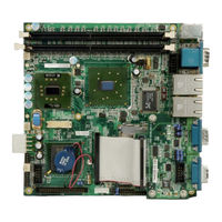
IEI Technology A200C-800Z-R10 User Manual (177 pages)
Mini ITX Celeron M 800MHz/Zero cache CPU Board with VGA/LCD,GbE, USB 2.0,Audio,With PCMCIA
Brand:
IEI Technology
| Category:
Motherboard
| Size: 7.23 MB
Table of Contents
Table of Contents
3
1 Introduction
15
A200 Motherboard Overview
16
A200 Motherboard Benefits
16
A200 Motherboard Features
16
A200 Motherboard Connectors
17
A200 Overview
17
Figure 1-1: A200 Motherboard Overview (Front Side)
17
Figure 1-2: A200 Motherboard Overview (Reverse Side)
19
POM-121IB Connectors
19
Figure 1-3: POM-121IB Overview (Front Side)
20
Figure 1-4: Expansion Daughter Board Overview (Reverse Side)
21
Figure 1-5: A200 Rear Panel Board
21
Rear Panel Interfaces
21
Technical Specifications
22
A200-800Z-R10 Motherboard Technical Specifications
22
POM-121IB Expansion Daughterboard Technical Specifications
23
Table 1-1: Technical Specifications
23
Table 1-2: POM-121IB Technical Specifications
23
2 Detailed Specifications
25
Cpu Support
26
Onboard Chipsets
26
Intel® 852GM Northbridge Chipset
26
Northbridge and Southbridge Chipsets
26
Intel® ICH4 Southbridge Chipset
27
Data Flow
27
Graphics Support
28
Figure 2-1: Data Flow Block Diagram
28
Memory Support
30
Pci Bus Interface Support
30
Gbe Ethernet
30
Drive Interfaces
31
IDE HDD Interfaces
31
PCMCIA Flash Card Support
31
Serial Ports
31
Real Time Clock
32
System Monitoring
32
Infrared Data Association (Irda) Interface
32
Usb Interfaces
32
Bios
32
Operating Temperature and Temperature Control
33
Audio Codec
33
Power Consumption
34
Table 2-1: Power Consumption
34
Packaged Contents and Optional Accessory Items
35
Optional Accessory Items
35
Package Contents
35
3 Connectors and Jumpers
37
Peripheral Interface Connectors
38
A200 Peripheral Interface Connectors
38
Figure 3-1: A200 Connector and Jumper Locations (Front Side)
38
Figure 3-2: A200 Connector and Jumper Locations (Reverse Side)
39
POM-121IB Peripheral Interface Connectors
40
Table 3-1: Peripheral Interface Connectors
40
Figure 3-3: POM-121IB Jumper and Connector Locations (Front Side)
41
Figure 3-4: POM-121IB Jumper and Connector Locations (Reverse Side)
41
Table 3-2: POM-121IB Peripheral Interface Connectors
41
Jumpers
42
Rear Panel Connectors
42
Table 3-3: Peripheral Interface Connectors
42
Internal Peripheral Connectors
43
IDE Connectors
43
Table 3-4: Onboard Jumpers
43
Figure 3-5: A200 IDE Device Connector Locations
44
Figure 3-6: POM-121IB IDE Device Connector Location
44
COM2 Serial Port Connector
45
Table 3-5: IDE Device Connector Pinouts
45
Figure 3-7: A200 COM2 Port Location
46
Figure 3-8: POM-121IB COM3 Port Location
46
Figure 3-9: IR Interface Connector Location
47
Infrared (Irda) Interface Connector
47
Table 3-6: COM Serial Port Connector Pinouts
47
Internal USB Connector
48
Table 3-7: IR Interface Connector Pinouts
48
CPU Cooling Fan Connector
49
Figure 3-10: USB Port Connector Location
49
Table 3-8: USB Connector Pinouts
49
Figure 3-11: CPU Cooling Fan Connector Location
50
Table 3-9: CPU Cooling Fan Pinouts
50
Audio Connector
51
Figure 3-12: ATXCTL1 Connector Locations
51
Figure 3-13: VGA Connector Location
52
Table 3-10: Audio Connector Pinouts
52
VGA Connector
52
Figure 3-14: Power Connector Location
53
Power Connector
53
Table 3-11: VGA Connector Pinouts
53
ATXCTL Connector
54
Figure 3-15: ATXCTL Connector Location
54
Table 3-12: Power Connector Pinouts
54
Figure 3-16: LVDS Connector Location
55
LVDS LCD Connector
55
Table 3-13: ATXCTL Connector Pinouts
55
Digital I/O Connector
56
Table 3-14: LVDS Connector Pinouts
56
Figure 3-17: DIO Connector Location
57
Front Panel Connector
57
Table 3-15: DIO Connector Pinouts
57
Figure 3-18: Front Panel Connector Location
58
Table 3-16: Front Panel Connector Pinouts
58
Figure 3-19: Power Extension Connector Location
59
Power out Connector
59
Figure 3-20: LCD Backlight Connector Location
60
LCD Backlight Connector
60
Table 3-17: Power Extension Connector (CN2) Pinouts
60
External (Rear Panel) Connectors
61
Figure 3-21: A200 Motherboard Rear Panel
61
Table 3-18: LCD Backlight Connector Pinouts
61
Figure 3-22: Dual PS/2 Pinouts and Configuration
62
Keyboard/Mouse Connector
62
Figure 3-23: Serial Port (COM1) and VGA Connector
63
Serial Port and VGA Connector
63
Table 3-19: PS/2 Connector Pinouts
63
LAN and USB Connectors
64
Table 3-20: VGA Connector Pinouts
64
Table 3-21: Serial Port (COM1) Connector Pinouts
64
Figure 3-24: RJ-45 and Dual USB Connectors
65
Figure 3-25: RJ-45 Ethernet Connector
65
Table 3-22: LAN Pinouts
65
Table 3-23: USB Pinouts
65
Figure 3-26: COM3 and COM4 Connectors
66
Serial Port Connectors
66
Table 3-24: RJ-45 Ethernet Connector Leds
66
Serial Port Connectors
67
Table 3-25: COM3 Pinouts (RS-232 Mode)
67
Table 3-26: COM4 Pinouts (RS-232 Mode)
67
Table 3-27: COM4 Pinouts (RS-422/452 Mode)
67
Onboard Jumpers
68
Figure 3-27: COM3 and COM4 Connectors
68
LVDS Panel Voltage Selection Jumper
69
Table 3-28: Jumpers
69
Table 3-29: JP1 Jumper Settings
69
Figure 3-28: JP1 Pinout Locations
70
Reset CMOS Jumper
70
COM4 Mode Selection Jumpers
71
Figure 3-29: CLR_CMOS Pinout Locations
71
Table 3-30: CLR_CMOS Jumper Settings
71
COM4 in RS-232 Mode
72
Figure 3-30: COM4 Mode Jumper Pinout Locations
72
COM4 in RS-422/452 Mode
73
Convert COM3/COM4 RI Pin to 5V/12V
73
Figure 3-31: COM3 RI Pin Selection Pinout Locations
74
Setting COM3 Pin 9 (RI or Voltage)
74
Figure 3-32: COM4RI Pin Selection Pinout Locations
75
Setting COM4 Pin 9 (RI or Voltage)
75
4 Installation and Configuration
77
Installation Considerations
78
Installation Notices
78
Unpacking
79
Checklist
79
Unpacking Precautions
79
A200 Motherboard Installation
80
Preinstalled Components
80
Components to Install
81
DIMM Module Installation
81
Peripheral Device Connection
81
Purchasing the Memory Module
81
Compact Flash Connector
82
IDE Disk Drive Connector (IDE1)
82
Table 4-1: IEI Provided Cables
82
Chassis Installation
83
Rear Panel Connectors
83
Ethernet Connection
83
LCD Panel Connection
83
USB Connection
83
5 Ami Bios Setup
85
Introduction
86
Starting Setup
86
Using Setup
86
BIOS Menu Bar
87
Getting Help
87
Table 5-1: BIOS Navigation Keys
87
Unable to Reboot after Configuration Changes
87
Main
88
System Overview
88
Advanced
89
CPU Configuration
90
Execute Bit Disable
91
Menu 3: CPU Configuration
91
CPU TM Function
92
IDE Configuration
92
Onboard PCI IDE Controller [Both]
92
IDE Master and IDE Slave
93
Auto-Detected Drive Parameters
94
IDE Master, IDE Slave
94
Type [Auto]
95
Zip
95
Block (Multi Sector Transfer) [Auto]
96
Lba/Large Mode [Auto]
96
PIO Mode [Auto]
96
32Bit Data Transfer [Enabled]
97
Auto]
97
DMA Mode [Auto]
97
Serial Port1 Address [3F8/IRQ4]
98
Super IO Configuration
98
Serial Port2 Address [2F8/IRQ3]
99
Serial Port2 Mode [Normal]
99
Serial Port3 Address [3E8]
99
Hardware Health Configuration
100
Serial Port3 IRQ [11]
100
Serial Port4 Address [2E8]
100
Serial Port4 IRQ [10]
100
Menu 7: Hardware Health Configuration
101
ACPI Aware O/S [Yes]
102
ACPI Configuration
102
MPS Configuration
103
MPS Revision [1.1]
103
USB Configuration
104
USB Devices Enabled
104
USB Function [Enabled]
104
Legacy USB Support [Disabled]
105
USB 2.0 Controller [Enabled]
105
USB Mass Storage Device Configuration
105
USB2.0 Controller Mode [Hispeed]
105
Device #1
106
USB Mass Storage Delay [20 Sec]
106
Menu 11: USB Mass Storage Device
106
Boot
107
Boot Settings Configuration
108
Quick Boot [Enabled]
108
Bootup Num-Lock [Off]
109
PS/2 Mouse Support [Enabled]
109
Quiet Boot [Disabled]
109
Boot from LAN Support [Disabled]
110
Hit 'DEL' Message Display [Enabled]
110
Wait for 'F1' if Error [Enabled]
110
Boot Device Priority
111
Hard Disk Drives
112
Removable Drives
112
Menu 15: Removable Drives
113
CD/DVD Drives
114
Security
114
Change Supervisor Password
115
User Access Level [Full Access]
115
Menu 16: Security
115
Change User Password
116
Chipset
116
Password Check [Setup]
116
Northbridge Configuration
117
Configure DRAM Timing by SPD [Enabled]
118
DRAM Frequency [200]
118
Menu 18:Northbridge Chipset Configuration [Chipset]
118
DRAM CAS# Latency [2.5]
119
DRAM RAS# Precharge [3 Clocks]
119
DRAM Burst Length
120
DRAM Precharge Delay [7 Clocks]
120
DRAM RAS# to CAS# Delay [3 Clocks]
120
Memory Hole [Disabled]
120
Graphics Aperture Size [64MB]
121
Init. Graphic Adapter Priority [Internal VGA]
121
Internal Graphics Mode Select [Enable, 32MB]
121
Boot Display Device [CRT]
122
Flat Panel Type [640X480 18Bit LVDS]
122
Onboard AC97
123
Onboard LAN1 [Enabled]
123
Southbridge Configuration
123
Spread Spectrum Mode
123
Onboard LAN2 [Enabled]
124
Power
124
Power Button Mode [On/Off]
125
Power Management/Apm [Enabled]
125
Restore on AC Power Loss [Last State]
125
Resume on PME# [Disabled]
126
Resume on Ring [Disabled]
126
Resume on RTC Alarm [Disabled]
126
RTC Alarm Date (Days)
126
System Time
126
Discard Changes and Exit
127
Exit
127
Save Changes and Exit
127
Discard Changes
128
Load Failsafe Defaults
128
Load Optimal Defaults
128
6 Software Drivers
129
Available Software Drivers
130
Chipset Driver Installation
130
Figure 6-1: Installshield Wizard Preparation Screen
130
Figure 6-2: Welcome Screen
131
Figure 6-3: License Agreement
131
Figure 6-4: Readme Information
132
Realtek Audio Driver Installation
133
Figure 6-5: Restart the Computer
133
Figure 6-6: Audio Driver Install Shield Wizard Starting
134
Figure 6-7: Audio Driver Setup Preparation
134
Figure 6-8: Audio Driver Welcome Screen
135
Figure 6-9: Audio Driver Software Configuration
135
Figure 6-10: Audio Driver Digital Signal
136
Figure 6-11: Audio Driver Installation Begins
137
Intel Graphics Media Accelerator Driver
138
Figure 6-12: Audio Driver Installation Complete
138
Figure 6-13: GMA Driver Installation Welcome Screen
139
Figure 6-14: GMA Driver License Agreement
140
Figure 6-15: GMA Driver Installing Notice
140
Lan Driver Installation
141
Figure 6-16: GMA Driver Installation Complete
141
Figure 6-17: LAN License Agreement
142
Figure 6-18: Select the Driver Directory
142
Figure 6-19: LAN Driver Configuration
143
Abios Configuration Options
145
A.1 BIOS Configuration Options
146
Bios Configuration Options
146
Bwatchdog Timer
149
Caddress Mapping
153
Io Address Map
154
St Mb Memory Address Map
154
Addres Map
154
Irq Mapping Table
155
Dma Channel Assignments
155
Dexternal Ac'97 Audio Codec
157
Introduction
158
Physical Connection
159
Driver Installation
160
Sound Effect Configuration
161
Sound Effect
162
Environment Simulation
162
Karaoke Mode
163
Equalizer Selection
164
Speaker Configuration
165
Speaker Test
166
S/PDIF-In & S/PDIF-Out
167
Connector Sensing
167
Hrtf Demo
170
Microphone Effect
171
General
172
Eindex
173
Advertisement
Advertisement
Related Products
IEI Technology AFOLUX CX Series
IEI AFL2-17AB-H61-P/R-R12
IEI Technology AFL2-17AB-H61-i5/PC-R12
IEI Technology ACT-457A
IEI Technology AFOLUX AFL-ATOM Series
IEI Technology AFL-10A-N270/R/1G-R22
IEI Technology AFL-W19A-GM45
IEI Technology AFL2-17AB-H61-i5/R-R13
IEI Technology AFL2-12A-HM65/PC-R11
IEI Technology AFL2-W19AB-H61-P/PC-R11
IEI Technology Categories
Motherboard
Touch Panel
Computer Hardware
Single board computers
Desktop
More IEI Technology Manuals
Login
Sign In
OR
Sign in with Facebook
Sign in with Google
Upload manual
Upload from disk
Upload from URL