Advertisement
Quick Links
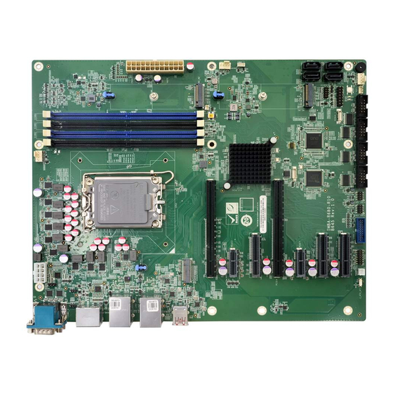
ATX Motherboard Supports LGA1700 12th/13th Gen. Intel® Core™
i9/i7/i5/i3, Pentium® and Celeron® Processor, DDR5,
Triple Independent Display, Dual 2.5GbE LAN, M.2,
Quick Installation Guide
Package List
IMBA-R680 package includes the following items:
1 x IMBA-R680 single board computer
2 x SATA cable
1 x I/O shielding
1 x QIG
USB 3.2, SATA 6Gb/s, and RoHS
IMBA-R680
Version 1.0
July 28, 2022
©2022 Copyright by IEI Integration Corp.
All rights reserved.
Advertisement

Related Manuals for IEI Technology IMBA-R680


Summary of Contents for IEI Technology IMBA-R680
- Page 1 USB 3.2, SATA 6Gb/s, and RoHS IMBA-R680 Quick Installation Guide Version 1.0 July 28, 2022 Package List IMBA-R680 package includes the following items: 1 x IMBA-R680 single board computer 2 x SATA cable 1 x I/O shielding ...
-
Page 2: Specifications
Specifications CPU: LGA1700 12 Generation Intel® Core™ i9/i7/i5/i3, Celeron® and Pentium® processors (up to 125W TDP) Chipset: Intel® R680E Memory: Four 288-pin 4800 MHz dual-channel unbuffered DDR5 SDRAM DIMM slots supporting up to 128 GB memory (ECC & non-ECC supported) ... - Page 3 Audio: 1 x iAUDIO supports IEI AC-KIT-888S Audio Kit (2x5 pin) Front Panel: 1 x Front panel (2x7 pin, p=2.54; power LED, HDD LED, speaker, power button, reset button) LAN LED: 2 x LAN LED (1x2 pin, p=2.0) ...
- Page 4 IEI Resource Download Center All the drivers and utility for the IMBA- https://download.ieiworld.com R680 are available on IEI Resource Download Center. Type IMBA-R680 and press Enter to find all the relevant software, utilities, and documentation. To install software from the downloaded ISO file, mount the file as a virtual drive to view its content.
-
Page 5: Ordering Information
Ordering Information IMBA-R680-R10: ATX motherboard supports LGA1700 12th/13th Generation Intel® Core™ i9/i7/i5/i3, Pentium® and Celeron® processor, DDR5, triple independent display, dual 2.5GbE LAN, M.2, USB 3.2, SATA 6Gb/s, and RoHS AC-KIT-888S-R10: Realtek ALC888S 7.1 Channel HD Audio board, RoHS ... -
Page 6: Jumpers Setting And Connectors
Jumpers Setting and Connectors LABEL FUNCTION J_ATX_AT1 AT/ATX power mode setting J_CMOS1 Clear CMOS jumper ME_FLASH1 Flash descriptor security override jumper IAUDIO Audio connector for IEI AC-KIT-888S kit ATX1 ATX power connector CPU12V1 ATX CPU 12V power connector BAT2 RTC battery connector CHASSIS1 Chassis intrusion connector DIMM1, DIMM2,... - Page 7 COM1_2 External dual RS-232/422/485 connector HDMI_DP1 External HDMI and DP combo connector External 2.5GbE RJ-45 and dual USB 3.2 LAN1_USB1 Gen 1 combo connector External 2.5GbE RJ-45 and dual USB 3.2 LAN2_USB2 Gen 2 combo connector USB3_1 External dual USB 3.2 Gen 2 connector J_ATX_AT1: AT/ATX Power Mode Setting PIN NO.
- Page 8 ATX1: ATX Power Connector PIN NO. DESCRIPTION PIN NO. DESCRIPTION +3.3V +3.3V +3.3V -12V PS_ON Power good 5VSB +12V +12V +3.3V CPU12V1: ATX CPU 12V Power Connector PIN NO. DESCRIPTION PIN NO. DESCRIPTION +12V +12V +12V +12V BAT2: RTC Battery Connector PIN NO.
- Page 9 DIO1 : Digital Input/Output Connector PIN NO. DESCRIPTION PIN NO. DESCRIPTION Output 5 Output 4 Output 3 Output 2 Output 1 Output 0 Input 5 Input 4 Input 3 Input 2 Input 1 Input 0 DEBUG_1: EC Debug Connector PIN NO. DESCRIPTION PIN NO.
- Page 10 F_PANEL1: Front Panel Connector DESCRIPTION DESCRIPTION PWR_LED+ SPKR+ SPKR PWR_LED- PWR_BTN+ SPKR- PWR_BTN- HDD_LED+ Reset+ RESET HDD_LED- Reset- J_I2C1: I C Connector PIN NO. DESCRIPTION PIN NO. DESCRIPTION I2C_CLK I2C_DATA JLAN_LED1: LAN1 Link LED Connector DESCRIPTION DESCRIPTION +3.3V I225_LINK_ACT_N JLAN_LED2: LAN2 Link LED Connector DESCRIPTION DESCRIPTION +3.3V...
- Page 11 SATA1, SATA2, SATA3, SATA4: SATA 6Gb/s Connectors PIN NO. DESCRIPTION PIN NO. DESCRIPTION SATA_RX‐ SATA_TX+ SATA RX+ SATA_TX‐ J_SMB1: SMBus Connector PIN NO. DESCRIPTION PIN NO. DESCRIPTION SMB_CLK SMB_DATA JSPI1: Flash SPI ROM Connector PIN NO. DESCRIPTION PIN NO. DESCRIPTION +3.3V SPI_CLK SPI_CS#...
- Page 12 USB3_2: Internal USB 3.2 Gen 1 Connector PIN NO. DESCRIPTION PIN NO. DESCRIPTION USB2_4_P USB3_RX3_N USB2_4_N USB3_RX3_P USB3_TX4_P USB3_TX3_N USB3_TX4_N USB3_TX3_P USB3_RX4_P USB2_3_N USB3_RX4_N USB2_3_P M2_M1: M.2 M-key Slot PIN NO. DESCRIPTION PIN NO. DESCRIPTION +3.3V +3.3V PCIE_4_RX_DN PCIE_4_RX_DP NGFF1_ACT_N PCIE_TX_DN4 +3.3V PCIE_TX_DP4...
- Page 13 PCIE_1_RX_DN PCIE_1_RX_DP PCIE_TX_DN1 PCIE_TX_DP1 PLT_RST_N SRCCLKREQB_17_N PCIE_CLK_DN17 PCIE_CLK_DP17 PEDET +3.3V +3.3V +3.3V M2_M2: M.2 M-key Slot PIN NO. DESCRIPTION PIN NO. DESCRIPTION +3.3V +3.3V PCIE_20_RX_DN PCIE_20_RX_DP NGFF2_ACT_N PCIE_TX_DN20 +3.3V PCIE_TX_DP20 +3.3V +3.3V PCIE_19_RX_DN +3.3V PCIE_19_RX_DP PCIE_TX_DN19 PCIE_TX_DP19...
- Page 14 PCIE_18_RX_DN PCIE_18_RX_DP PCIE_TX_DN18 PCIE_TX_DP18 M_2_SATA_SLP PCIE_17_RX_DN PCIE_17_RX_DP PCIE_TX_DN17 PCIE_TX_DP17 PERST_N SRCCLKREQB_15_N PCIE_CLK_DN15 PCIE_CLK_DP15 +3.3V +3.3V +3.3V...
- Page 15 COM1, COM2: External RS-232/422/485 Connectors RS-232 RS-422 RS-485 TXD422- TXD485- TXD422+ TXD485+ RXD422+ RXD422- HDMI_DP1 External DP Connector PIN NO. DESCRIPTION PIN NO. DESCRIPTION LANE0P LANE3N LANE0N AUX_CTRL_DET_C LANE1P AUXP LANE1N LANE2P AUXN LANE2N LANE3P External HDMI Connector PIN NO. DESCRIPTION PIN NO.
- Page 16 HDMI_DATA0# HDMI_HPD HDMI_CLK LAN1_USB1 External Dual USB 3.2 Gen 1 Connector PIN NO. DESCRIPTION PIN NO. DESCRIPTION USB_DATA- USB_DATA- USB_DATA+ USB_ DATA+ USB3_RX- USB3_RX- USB3_RX+ USB3_ RX+ USB3_TX- USB3_TX- USB3_TX+ USB3_TX+ 2.5GbE RJ-45 Connector PIN NO. DESCRIPTION PIN NO. DESCRIPTION LAN1_MDI0P LAN1_MDI2P LAN1_MDI0N...
- Page 17 LAN2_USB2 External Dual USB 3.2 Gen 2 Connector PIN NO. DESCRIPTION PIN NO. DESCRIPTION USB_DATA- USB_DATA- USB_DATA+ USB_ DATA+ USB3_RX- USB3_RX- USB3_RX+ USB3_ RX+ USB3_TX- USB3_TX- USB3_TX+ USB3_TX+ 2.5GbE RJ-45 Connector PIN NO. DESCRIPTION PIN NO. DESCRIPTION LAN1_MDI0P LAN1_MDI2P LAN1_MDI0N LAN1_MDI2N LAN1_MDI1P LAN1_MDI3P...
- Page 18 Board Layout: Jumper and Connector Locations (Unit: mm)
Need help?
Do you have a question about the IMBA-R680 and is the answer not in the manual?
Questions and answers