Hameg HM7042-5 Manual
Hide thumbs
Also See for HM7042-5:
- User manual (28 pages) ,
- Service manual (22 pages) ,
- Manual (52 pages)
Table of Contents
Advertisement
Available languages
Available languages
Quick Links
Download this manual
See also:
User Manual
Advertisement
Chapters
Table of Contents

Related Manuals for Hameg HM7042-5


Summary of Contents for Hameg HM7042-5
- Page 1 P o w e r s u p p l y H M 7 0 4 2 - 5 Handbuch / Manual / Manuel Deutsch / English / Français...
-
Page 2: Konformitätserklärung
Schnittstellenkabel möglich, so darf jeweils nur eines angeschlossen sein. Bei Datenleitungen ist generell auf doppelt abgeschirmtes Verbindungskabel zu achten. Als IEEE-Bus Kabel sind die von HAMEG beziehbaren doppelt geschirmten Kabel HZ72S bzw. HZ72L geeignet. 2. Signalleitungen Messleitungen zur Signalübertragung zwischen Messstelle und Messgerät sollten generell so kurz wie möglich gehalten werden. -
Page 3: Table Of Contents
Sehr geehrter Kunde, sehr geehrte Kundin, Um den Ablauf einer Reparatur zu beschleunigen, hat HAMEG ein neues Verfahren eingeführt: Das RMA- Verfahren (R R R R R eturn M M M M M aterial A A A A A uthorization). Daher bitten wir alle Kunden, vor Einsendung eines Gerätes, eine RMA-Nummer anzufordern. -
Page 4: Deutsch
H M 7 0 4 2 - 5 D r e i f a c h N e t z g e r ä t H M 7 0 4 2 - 5 2 x 0-32 / 0-2 A und 1 x 0-5,5 V / 0-5 A Anzeigen für Strom und Spannung: 4-stellig bei Kanal I + III;... -
Page 5: Dreifach Netzgerät Hm7042-5
T e c h n i s c h e D a t e n Dreifach Netzgerät HM7042-5 Technische Daten Technische Daten Technische Daten Technische Daten Technische Daten (bei +23 bei +23 bei +23 bei +23 bei +23 °C °C °C... -
Page 6: Wichtige Hinweise
(z.B. im Freien oder in feuchten Räumen) – Schwere Transportbeanspruchung Bleiben die vorderen Gerätefüße eingeklappt, wie in Bild 2, lässt sich das Gerät mit vielen weiteren Geräten von HAMEG Überschreiten der Schutzkleinspannung! Bei sicher stapeln. Reihenschaltung aller Ausgangsspannungen des Werden mehrere Geräte aufeinander gestellt sitzen die ein- HM 7042-5 kann die Schutzkleinspannung von 42 V geklappten Gerätefüße in den Arretierungen des darunter lie-... -
Page 7: Bestimmungsgemäßer Betrieb
Sie sich bitte an den Händler, bei dem (Klingenbreite ca. 2 mm) werden die an der linken und rech- Sie Ihr HAMEG Produkt erworben haben. Um den Ablauf zu ten Seite des Sicherungshalters befindlichen Kunststoff- beschleunigen, können Kunden innerhalb der Bundesrepublik arretierungen nach innen gedrückt. -
Page 8: Bezeichnung Der Bedienelemente
B e z e i c h n u n g d e r B e d i e n e l e m e n t e VOLTAGE Einstellregler Spannung 0...5,5 V Bezeichnung der Bedienelemente CURRENT Einstellregler für I der Strom- begrenzung / elektronischen Sicherung... -
Page 9: Netzgerätegrundlagen
Die Größe der Ausgangsspannung und die übertragene Leis- tung lässt sich durch die Einschaltdauer des Schalttransis- sind. Dies ist bei HAMEG Netzgeräten der Fall. Die Ausgangs- tors regeln. Prinzipiell werden zwei Arten von getakteten spannungen, welche kombiniert werden sollen, sind in der Netzteilen unterschieden: Regel voneinander unabhängig. -
Page 10: Strombegrenzung
Wie man sieht, addieren sich bei dieser Art der dimensioniert. Verwenden Sie Netzgeräte eines Verschaltung die einzelnen Ausgangsspannungen. anderen Herstellers als HAMEG, welche nicht Die dabei entstehende Gesamtspannung kann überlastsicher sind, können diese durch die dabei leicht die Schutzkleinspannung von 42 V ungleiche Verteilung zerstört werden. -
Page 11: Einführung In Die Bedienung Des Hm7042-5
Ein- / Ausschalten der Ausgänge Ein- / Ausschalten der Ausgänge Ein- / Ausschalten der Ausgänge Bei allen HAMEG Netzgeräten lassen sich die Ausgangs- spannungen durch Tastendruck Ein- und Ausschalten. Das Netzgerät selbst bleibt dabei eingeschaltet. Somit lassen sich vorab die gewünschten Ausgangsgrößen komfortabel einstel- “... -
Page 12: Bedienelemente Und Anzeigen
B e d i e n e l e m e n t e u n d A n z e i g e n Kanal II (0-5,5V / 5A) Bedienelemente und Anzeigen Ausgangspannung regelbar von 0 - 5,5 V. Sicherheitsbuchsen für 4mm-Sicherheitsstecker. - Page 13 Der Kurzschluss des Aus- gangs wird nun entfernt. ELECTRONIC FUSE wird betä- tigt. Die LED [ON] leuchtet. Das HM7042-5 befindet sich im Modus elektronische Sicherung. Wird jetzt der Grenzwert I eines Ausganges erreicht, werden alle Ausgänge gleichzeitig abgeschaltet.
-
Page 14: English
General remarks regarding the CE marking 3. External influences HAMEG measuring instruments comply with the EMI norms. Our tests In the vicinity of strong magnetic or/and electric fields even a careful for conformity are based upon the relevant norms. Whenever different... - Page 15 T a b l e o f c o n t e n t Deutsch English Declaration of Conformity General remarks regarding the CE marking Triple Power Supply HM7042-5 Specifications Important hints Used symbols Unpacking Positioning Transport Storage Safety instructions...
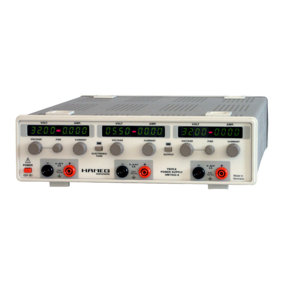
- Page 16 H M 7 0 4 2 - 5 T r i p l e P o w e r S u p p l y H M 7 0 4 2 - 5 2 x 0 – 32 V / 2 A and 1 x 0 – 5.5 V / 0 – 5 A Independent floating outputs Pushbutton for activating/deactivating outputs Separate voltage and current displays for each output:...
-
Page 17: Triple Power Supply Hm7042-5
LED: shows current limit Maximum ratings Max. voltage applicable to output terminals (ON/OFF): Included in delivery: Included in delivery: Included in delivery: HM7042-5 Power Supply, Included in delivery: Included in delivery: CH I + III: 33 V Manual, line cord... -
Page 18: Important Hints
The line voltage of the instrument must correspond to the If the feet are not used (picture 2) the instrument can be line voltage used. combined with many other HAMEG instruments. – Opening of the instrument is allowed only to qualified... -
Page 19: Warranty And Repair
Check fuse holder and line cord for any damages. Use a suitable screw driver of appr. 2 mm to depress the HAMEG instruments are subject to a strict quality control. All plastic fuse holder releases on both sides, the housing is instruments are burned in for 10 hrs prior to shipment. -
Page 20: Operating Controls
O p e r a t i n g c o n t r o l s VOLTAGE Adjustment of output voltage 0...5.5 V Operating controls CURRENT Adjustment of current limit I both current limit and electronic Front panel fuse threshold Œ... -
Page 21: Basics Of Power Supplies
This is the case with all OPVA voltage HAMEG supplies. As a rule, the output voltages to be combined are independent of each other, hence, it is allowed to connect reference voltage the outputs of one supply with those of another or more. -
Page 22: Current Limit
Switching the display on/off in order to protect a sensitive test circuit. In case of an All Hameg supplies feature a pushbutton which turns the inadvertent short in the test circuit the current will be limited outputs ON/OFF while the supply remains functioning. This to the value set which will in most cases prevent damage. -
Page 23: Survey Of Controls And Displays
O p e r a t i n g c o n t r o l s a n d d i s p l a y s Operating controls and displays 0 – 32 V / 2 A 0 – 5.5 V / 5 A Output voltage, adjustable 0 –... - Page 24 to be removed. Then Electronic Fuse is depressed, the LED [ON] will light up indicating that the HM7042-5 is in the Electronic Fuse mode. In this mode all outputs will be immediately deactivated if the I of one channel is reached.
- Page 25 O p e r a t i n g c o n t r o l s a n d d i s p l a y s Subject to change without notice...
-
Page 26: Français
Les instruments HAMEG répondent aux normes de la directive CEM. Une bonne liaison de masse est nécessaire. En liaison avec des Le test de conformité fait par HAMEG répond aux normes génériques générateurs de signaux, il faut utiliser des câbles à double blindage actuelles et aux normes des produits. - Page 27 Notions fondamentales sur les alimentations Alimentations linéaires Alimentations à découpage Fonctionnement en parallèle et en série Limitation du courant Fusible électronique Concept de la HM7042-5 Introduction à l’utilisation de la HM7042-5 Éléments de commande et indicateurs Sous réserve de modifications...
- Page 28 H M 7 0 4 2 - 5 A l i m e n t a t i o n t r i p l e H M 7 0 4 2 - 5 2 x 0-32V / 0-2A et 1 x 0-5,5V / 0-5A Affichage des valeurs du courant et de la tension : 4 chiffres pour les sorties I et III ;...
-
Page 29: Alimentation Triple Hm7042-5
Niveaux maximum Accessoires fournis: Accessoires fournis: Accessoires fournis: Accessoires fournis: Accessoires fournis: Tensions: Alimentation triple HM7042-5, câble d’alimentation, manuel Voies I +III 33 V Voie II Accessoires disponibles en option: Accessoires disponibles en option: Accessoires disponibles en option: Accessoires disponibles en option: Accessoires disponibles en option: HZ10 câble de mesure... -
Page 30: Remarques Importantes
La basse tension de sécurité de 42 V risque d’être Figure 3 dépassée en cas de branchement en série de toutes les tensions de sortie du HM7042-5. Notez qu’il existe dans ce cas un danger de mort lors d’un contact avec les pièces sous tension. Il est supposé... -
Page 31: Utilisation Conforme
Après expiration de la garantie, le service clientèle un seul et même élément et le remplacement du fusible ne HAMEG se tient à votre disposition pour toute réparation et peut avoir lieu qu’après avoir débranché l’appareil du secteur changement de pièce. -
Page 32: Désignation Des Éléments De Commande
D é s i g n a t i o n d e s é l é m e n t s d e c o m m a n d e VOLTAGE Bouton de réglage de la tension Désignation des éléments de commande 0 –... -
Page 33: Notions Fondamentales Sur Les Alimentations
Fonctionnement en parallèle et en série supérieur à celui des alimentations à régulation linéaire. Le composant de réglage à régulation continue (le transistor) de Les alimentations HAMEG ont été conçues pour être l’alimentation linéaire est remplacé par un commutateur branchées en série et/ou en parallèle. -
Page 34: Limitation Du Courant
Exemple: Un appareillage fonctionnant sous 12 V consomme un courant de 2,7 A. Chaque sortie 32 V du HM7042-5 peut délivrer un maximum de 2 A. Pour pouvoir alimenter cet appareillage Concept du HM7042-5 uniquement à partir du HM7042-5, il faut régler les tensions des deux sorties 32 V sur 12 V. -
Page 35: Introduction À L'utilisation De La Hm7042-5
Le courant maximum du HM7042-5 dans le cas d’un branche- ment en série est de 2 A. Un courant maximum de 4 A peut être obtenu avec un branchement en parallèle de deux sorties 0-32 V. -
Page 36: Éléments De Commande Et Indicateurs
É l é m e n t s d e c o m m a n d e e t i n d i c a t e u r s Éléments de commande et indicateurs 0-32 V / 2 A 0-5,5 V / 5 A Tension de sortie réglable de 0 à... - Page 37 CURRENT. Retirer le court-circuit de la sortie, appuyer sur ELECTRONIC FUSE , la LED (ON) s’allume. Le HM7042-5 se trouve en mode Fusible électronique. Si la valeur limite I d’une sortie est atteinte, toutes les sorties sont désactivées simultanément.
- Page 38 N o t i z e n / N o t e s / N o t a t i o n Sous réserve de modifications...
- Page 39 N o t i z / N o t e s / N o t a t i o n Sous réserve de modifications...
- Page 40 . h a m e g . d e Subject to change without notice HAMEG GmbH 43-7042-0560/01-10-2004-gw Industriestraße 6 © HAMEG GmbH D-63533 Mainhausen ® registriered trademark Tel +49 (0) 61 82 800-0 DQS-Certification: DIN EN ISO 9001:2000 Fax +49 (0) 61 82 800-100 Reg.-Nr.: 071040 QM...
Need help?
Do you have a question about the HM7042-5 and is the answer not in the manual?
Questions and answers