Hameg HM7042-5 User Manual
Triple power supply
Hide thumbs
Also See for HM7042-5:
- Manual (40 pages) ,
- Service manual (22 pages) ,
- User manual (13 pages)
Table of Contents
Advertisement
Available languages
Available languages
Quick Links
Download this manual
See also:
Manual
Advertisement
Chapters
Table of Contents

Related Manuals for Hameg HM7042-5


Summary of Contents for Hameg HM7042-5
- Page 1 HM7042-5 Triple Power Supply Benutzerhandbuch User Manual *5800447002* 5800447002...
-
Page 2: Allgemeine Hinweise Zur Ce-Kennzeichnung
Spannungsgrenzen (2006/95/ EG) [LVD] Bei Datenleitungen ist generell auf doppelt abgeschirmtes z über die elektromagnetische Verträglichkeit Verbindungskabel zu achten. Als IEEE-Bus Kabel ist das von HAMEG beziehbare doppelt geschirmte Kabel HZ72 geeignet. (2004/108/EG) [EMCD] z über die Beschränkung der Verwendung bestimmter 2. -
Page 3: Table Of Contents
Bezeichnung der Bedienelemente Netzgeräte-Grundlagen Lineare Netzteile Getaktete Netzteile Parallel- und Serienbetrieb Gerätekonzept des HM7042-5 Einführung in die Bedienung des HM7042-5 Bedienelemente und Anzeigen Kanal I + III (0-32V / 2A) Kanal II (0-5,5V / 5A) Sonstige Bedienelemente Strombegrenzung Elektronische Sicherung (ELECTRONIC Fuse) - Page 4 H M 7 0 4 2 - 5 D r e i f a c h - N e t z g e r ä t H M 7 0 4 2 - 5 HZ42 19“ Einbausatz 2HE 2 x 0…32 V/0…2 A 1 x 0…5,5 V/0…5 A Leistungsfähiges und preiswertes Netzgerät für Labor- anwendungen...
-
Page 5: Dreifach-Netzgerät Hm7042-5
T e c h n i s c h e D a t e n Grenzwerte Gegenspannung: Dreifach-Netzgerät HM7042-5 CH 1 + CH 3 33 V Alle Angaben bei 23 °C nach einer Aufwärmzeit von 30 Minuten. CH 2 Falsch gepolte Spannung: max. -
Page 6: Wichtige Hinweise
HM7042-5 kann die Schutzkleinspannung von 42 V Bleiben die vorderen Gerätefüße eingeklappt, wie in Bild 2, überschritten werden. Beachten Sie, dass in die- lässt sich das Gerät mit vielen weiteren Geräten von HAMEG sem Fall das Berühren von spannungsführenden sicher stapeln. -
Page 7: Gewährleistung Und Reparatur
W i c h t i g e H i n w e i s e Feuchtigkeitsgehalt der Luft, bei Explosionsgefahr sowie bei Verwenden Sie keinen Alkohol, Lösungs- oder aggressiver chemischer Einwirkung betrieben werden. Scheuermittel. Keinesfalls darf die Reinigungs- flüssigkeit in das Gerät gelangen. Die Anwendung Der zulässige Umgebungstemperaturbereich während des anderer Reinigungsmittel kann die Kunststoff- und Betriebes reicht von +5 °C...+40 °C. -
Page 8: Bezeichnung Der Bedienelemente
B e z e i c h n u n g d e r B e d i e n e l e m e n t e CURRENT Einstellregler für I 2 Bezeichnung der Bedienelemente Strombegrenzung / elektroni- schen Sicherung 0 –... -
Page 9: Netzgeräte-Grundlagen
Ausgangsleistung des Netzteiles „zerhackt“. Die Größe der Aus- den Parallelbetrieb und/oder Serienbetrieb dimensioniert sind. gangsspannung und die übertragene Leistung lässt sich durch Dies ist bei HAMEG Netzgeräten der Fall. Die Ausgangsspan- die Einschaltdauer des Schalttransistors regeln. Prinzipiell nungen, welche kombiniert werden sollen, sind in der Regel werden zwei Arten von getakteten Netzteilen unterschieden: voneinander unabhängig. - Page 10 Ein Verbraucher zieht an 12 V einen Strom von 2,7 A. Jeder werden. 32-V-Ausgang des HM7042-5 kann maximal 2 A. Damit nun der Verbraucher mit dem HM7042-5 versorgt werden kann, sind die Ausgangsspannungen beider 32-V-Ausgänge auf 12 V einzustellen.
-
Page 11: Gerätekonzept Des Hm7042-5
Beim Einschalten sind die Ausgänge immer ausgeschaltet. Dies dient der Sicherheit der angeschlossenen Verbraucher. Es sollte immer zuerst die benötigte Ausgangsspannung Der Maximalstrom vom HM7042-5 ist bei Reihenschaltung auf eingestellt werden. Danach werden die Ausgänge des HM7042-5 2 A begrenzt. Durch Parallelschaltung der beiden Ausgangs- mit OUTPUT zugeschaltet. -
Page 12: Bedienelemente Und Anzeigen
B e d i e n e l e m e n t e u n d A n z e i g e n zung leuchtet die LED und die Ausgangsspannung sinkt 6 Bedienelemente und Anzeigen auf 0 Volt ab. Kanal II (0-5,5V / 5A) Kanal I + III (0-32V / 2A) Ausgangspannung regelbar von 0 - 5,5 V. -
Page 13: Sonstige Bedienelemente
Wert von I eingestellt. Der Kurzschluss des Ausgangs wird nun entfernt. ELECTRONIC FUSE wird betätigt. Die LED [ON] leuchtet. Das HM7042-5 befindet sich im Modus elektroni- sche Sicherung. Wird jetzt der Grenzwert I eines Ausganges erreicht, werden alle Ausgänge gleichzeitig abgeschaltet. -
Page 14: General Remarks Regarding The Ce Marking
G e n e r a l r e m a r k s r e g a r d i n g t h e C E m a r k i n g General remarks regarding the CE marking HAMEG measuring instruments comply with the EMI norms. Our tests for conformity are based upon the relevant norms. Whenever different maximum limits are optional HAMEG will select the most stringent ones. - Page 15 T a b l e o f c o n t e n t Deutsch English General remarks regarding the CE marking Triple Power Supply HM7042-5 Specifications Important hints Symbols Unpacking Positioning Transport / Storage Safety instructions Proper operating conditions...
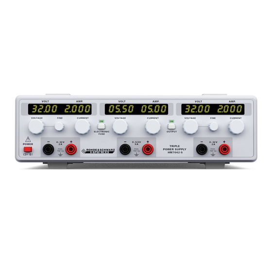
- Page 16 H M 7 0 4 2 - 5 T r i p l e P o w e r S u p p l y H M 7 0 4 2 - 5 HZ42 19“ Rackmount Kit 2RU R 2 x 0…32 V/0…2 A 1 x 0…5.5 V/0…5 A R High-performance and inexpensive laboratory power supply R Floating, overload and short-circuit proof outputs...
-
Page 17: Triple Power Supply Hm7042-5
S p e c i f i c a t i o n s Triple Power Supply HM7042-5 All data valid at 23 °C after 30 minutes warm-up. Outputs 2 x 0…32 V/2 A and ON/OFF pushbutton control, SMPS 0…5.5 V/5A... -
Page 18: Important Hints
Opening of the instrument is allowed only to qualified per- If the feet are not used (picture 2) the instrument can be com- sonnel bined with many other HAMEG instruments. – Prior to opening the instrument must be disconnected from the line and all other inputs/outputs. -
Page 19: Warranty And Repair
I m p o r t a n t h i n t s class 2. The instrument may be used in any position, however, sufficient ventilation must be assured as convection cooling is used. For continuous operation prefer a horizontal or slightly upward position using the feet. -
Page 20: Operating Controls
O p e r a t i n g c o n t r o l s 2 Operating controls CURRENT Adjustment of current limit I Front panel both current limit and electronic fuse threshold VOLT Voltage display AMP. Current display 0 –... -
Page 21: Basics Of Power Supplies
It is mandatory that the power supplies used are definitely specified for these operating modes. This is the case with all HAMEG supplies. As a rule, the output voltages to be combined OPVA are independent of each other, hence, it is allowed to connect... -
Page 22: Current Limit
Example: Exceeding the safety voltage level of 42 V! A load requires 12 V at 2.7 A. Each 32 V output of the HM7042-5 can deliver 2 A. First set both supplies to 12 V. Then connect both If all outputs are series connected the maximum black and both red safety connectors respectively in parallel. -
Page 23: Operating Controls And Displays
O p e r a t i n g c o n t r o l s a n d d i s p l a y s activated. In case “Current limit“ was selected the LEDs 6 Operating controls and displays will light up, the voltage will drop to zero. - Page 24 , the short has to be remov- ed. Then Electronic Fuse is depressed, the LED [ON] will light up indicating that the HM7042-5 is in the Electronic Fuse mode. In this mode all outputs will be immediately deactivated if the I of one channel is reached.
- Page 25 O p e r a t i n g c o n t r o l s a n d d i s p l a y s Subject to change without notice...
- Page 26 Subject to change without notice...
- Page 27 Subject to change without notice...
- Page 28 Service: www.service.rohde-schwarz.com Subject to change – Data without tolerance limits is not binding. R&S ® is a registered trademark of Rohde & Schwarz GmbH & Co. KG. Trade names are trademarks of the owners. 5800.4470.02 │ Version 03 │HM7042-5...
Need help?
Do you have a question about the HM7042-5 and is the answer not in the manual?
Questions and answers