Table of Contents
Advertisement
Quick Links
READ AND SAVE THESE INSTRUCTIONS
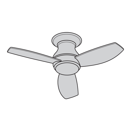
CURVA SKY LED OUTDOOR
44" & 52" Wet Location Snugger
Ceiling Fan Owner's Manual
44" Model Numbers
CF144LGRT00
Graphite
CF144LORB00
Oil Rubbed Bronze
CF144LWW00
Appliance White
Questions, problems, missing parts: Before returning to the store, Call Customer Service
BP7536-1 Curva Sky Outdoor (EnSpFr) 202101275.indb 1
BP7536-1 Curva Sky Outdoor (EnSpFr) 202101275.indb 1
52" Model Numbers
CF152LGRT00
CF152LORB00
Oil Rubbed Bronze
CF152LWW00
Appliance White
1-888-757-7697
Graphite
U.L. Model No.: CF144L & CF152L
1/27/21 11:10 AM
1/27/21 11:10 AM
Advertisement
Table of Contents

Related Manuals for Emerson CF144LGRT00


Summary of Contents for Emerson CF144LGRT00
- Page 1 READ AND SAVE THESE INSTRUCTIONS CURVA SKY LED OUTDOOR 44” & 52” Wet Location Snugger Ceiling Fan Owner’s Manual 44” Model Numbers 52” Model Numbers CF152LGRT00 CF144LGRT00 Graphite Graphite CF152LORB00 CF144LORB00 Oil Rubbed Bronze Oil Rubbed Bronze CF152LWW00 CF144LWW00 Appliance White...
-
Page 2: Table Of Contents
Table of Contents Section Section Safety Instructions 9 . Maintenance 1 . Unpacking Instructions 10 . Repair Parts 2 . Electrical Requirements 11 . Troubleshooting 3 . Ceiling Fan Assembly 12 . Energy Efficient Use of Ceiling Fan 4 . How to Hang Your Ceiling Fan 5 . -
Page 3: Unpacking Instructions
1. Unpacking Instructions PACKAGE CONTENTS Part Description Quantity Fan Motor Assembly Ceiling Trim Ring Ceiling Mounting Plate Fan Blades Lower Housing LED Light Fixture Assembly Glass No-Light Cover 6-Speed Electronic Receiver Control with Parts Bag 6-Speed Handheld Transmitter with Wall Bracket PROTECTIVE PLASTIC BAG Remove the fan motor... -
Page 4: Electrical Requirements
1. Unpacking Instructions (Continued) THESE FAN MODELS ARE SUITABLE FOR WET LOCATIONS SUCH AS PORCHES, PATIOS, AND DECKS. This Manual Is Designed to Make it as Easy as Possible for You to Assemble, Install, Operate and Maintain Your Ceiling Fan Tools Needed for Assembly One Phillips Head Screwdriver One Stepladder... -
Page 5: Ceiling Fan Assembly
3. Ceiling Fan Assembly M5 x 16 mm FLANGE HEAD BLADE SCREWS (3 per blade) FAN BLADE SLIDE FAN BLADE INTO BLADE CENTER SLOT FAN MOTOR ASSEMBLY WARNING BLADE SLOT To reduce the risk of personal injury, do not bend Figure 1 the blades during installation, balancing the blades or cleaning the fan. - Page 6 3. Ceiling Fan Assembly (Continued) Remove one of the three M4 x 10 mm Pan Head LED LIGHT FIXTURE Screws in the Lower Housing and loosen the remaining ASSEMBLY two screws . Retain the M4 x 10 mm Pan Head Screw for future use . Tuck wires into the LED Light Fixture Assembly and CUT OUT position in the Lower Housing Assembly .
- Page 7 CAUTION CEILING To reduce the risk of injury, install the fan so that the blades are at least 7 ft. (2.1m) above the floor (Figure 6). WARNING Turning off wall switch is not sufficient. To avoid LEAST possible electrical shock, be sure electricity is turned off at the main fuse box before wiring.
- Page 8 Slide the Ceiling Trim Ring over the Fan Motor Assembly and let it rest on the Fan Motor Assembly FAN MOTOR ASSEMBLY (Figure 8) . CEILING TRIM RING Figure 8 Place the Fan Motor Assembly onto the Ceiling Mounting Plate Hook during wiring Fan Motor Assembly to Outlet Box (Figure 9) .
-
Page 9: How To Wire Your Ceiling Fan
5. How to Wire Your Ceiling Fan If you feel that you do not have enough electrical WARNING wiring knowledge or experience, have your fan installed by a licensed electrician. Turning off wall switch is not sufficient. To avoid possible electrical shock, be sure electricity is turned off at the main fuse box before wiring. - Page 10 5. How to Wire Your Ceiling Fan (Continued) MOUNTING Securely connect the Supply White Wire (neutral) to PLATE the Receiver White Wire (AC IN N)/(TO MOTOR N) SUPPLY and White Fan Wire (neutral) using a Wire Connector WHITE WIRE (Figure 12) . WIRE CONNECTOR RECEIVER...
- Page 11 Figure 15 RECEIVER GREEN GROUND WIRE WHITE BLACK RECEIVER SUPPLY WIRE WIRE BLACK RECEIVER WHITE WIRE SUPPLY WIRE BLACK/WHITE RECEIVER WIRE BLUE RECEIVER WIRE BLUE FAN WIRE WHITE FAN WIRE GREEN MOUNTING BLACK FAN WIRE PLATE WIRE GREEN FAN WIRE Figure 16 BP7536-1 Curva Sky Outdoor (EnSpFr) 202101275.indb 11 BP7536-1 Curva Sky Outdoor (EnSpFr) 202101275.indb 11...
- Page 12 Remove and retain one of the four M5 x 10 mm Pan Head Ceiling Cover Screws and Split Washers in the Ceiling Mounting Plate . Loosen the remaining three M5 x 10 mm Pan Head Ceiling Cover Screws and Split Washers (Figure 17) . Unhook the Fan Motor Assembly from the Ceiling Mounting Plate Hook and lift the Fan Motor Assembly up to the Ceiling Mounting Plate .
- Page 13 Place the Glass into the opening in the Lower Housing, aligning the three Flat Areas on the top edge of the Glass with the three raised Dimples on the Lower Housing and turn the Glass clockwise until it stops (Figure 19) . NOTE: Periodically check that the Glass is seated fully clockwise in the Lower Housing.
-
Page 14: Optional Installation Of No-Light Cover
7. Optional Installation of No-Light Cover NOTE: To use the No-Light Cover, the LED Light Fixture Assembly MUST NOT Be Installed, or the LED Light Fixture Assembly MUST Be Removed. WARNING Turning off wall switch is not sufficient. To avoid possible electrical shock, be sure electricity is turned off at the main fuse box before wiring. - Page 15 7. Optional Installation of No-Light Cover (Continued) Disconnect the LED Light Fixture Assembly wire terminals from the Fan Motor Assembly wire terminals . (Figure 22) . Store the LED Light Fixture Assembly in a safe location for future installation . Tuck the Fan Motor Assembly wires and connectors into the Lower Housing prior to assembling the No-Light FAN MOTOR...
-
Page 16: Remote Control Procedures
8. Remote Control Procedures 8.1: Preset Memory Feature WARNING Your Receiver is equipped with a preset memory feature . If the AC supply to the Receiver is powered Fan installation must be completed, including the installation of the fan blades, before testing the remote through a Wall Switch, when the Switch is turned OFF, control. - Page 17 Your Remote Control has full control of your Ceiling Fan and Light . POWER INDICATOR When power is restored, push and hold the FAN LIGHT POWER OFF Button ( ) for 3 to 5 Seconds to set the Code in the Receiver (Figure 26) . FAN POWER OFF BUTTON NOTE: The Ceiling Fan Lights (if installed) will Blink...
- Page 18 8.8: Storage Bracket Installation A Storage Bracket is provided for holding your Remote Control when not in use . If you desire to use the Bracket, install it on a wall that is away from excess heat or humidity . COVER Slide the Wall Bracket Cover up to expose the Screw Holes for installation (Figure 30) .
-
Page 19: Maintenance
9. Maintenance IMPORTANT CARE INSTRUCTIONS WARNING for your Ceiling Fan Do not use water when cleaning your ceiling fan. Periodic cleaning of your new ceiling fan is the only It could damage the motor or the blades and create the maintenance that is needed . -
Page 20: Repair Parts
10. Repair Parts PARTS BAG 8 - 52" 9 - 44" BP7536-1 Curva Sky Outdoor (EnSpFr) 202101275.indb 20 BP7536-1 Curva Sky Outdoor (EnSpFr) 202101275.indb 20 1/27/21 11:10 AM 1/27/21 11:10 AM... -
Page 21: Troubleshooting
11. Troubleshooting WARNING FOR YOUR OWN SAFETY TURN OFF POWER AT FUSE BOX OR CIRCUIT BREAKER BEFORE TROUBLESHOOTING YOUR FAN. TROUBLE PROBABLE CAUSE SUGGESTED REMEDY 1. Fan will not start. 1 . Fuse or circuit breaker blown . 1 . Check main and branch circuit fuses or circuit breakers . WARNING Make sure main power is turned OFF. - Page 22 SERIAL NUMBER: DATE CODE: The serial number of this fan can be found on the nameplate on top of the fan housing . The date code can be found on the carton and on top of the fan housing, stamped in ink on a white label . You should record this data above and keep it in a safe place for future use .
Need help?
Do you have a question about the CF144LGRT00 and is the answer not in the manual?
Questions and answers