Vega VEGAPULS SR 68 Operating Instructions Manual
Radar sensor for continuous level
measurement of bulk solids
Hide thumbs
Also See for VEGAPULS SR 68:
- Operating instructions manual (92 pages) ,
- Quick setup manual (24 pages) ,
- Product information (20 pages)
Table of Contents
Advertisement
Quick Links
Advertisement
Table of Contents

Related Manuals for Vega VEGAPULS SR 68


Summary of Contents for Vega VEGAPULS SR 68
-
Page 1: Operating Instructions
Tel: +44 (0)191 490 1547 Fax: +44 (0)191 477 5371 Email: northernsales@thorneandderrick.co.uk Website: www.heattracing.co.uk www.thorneanderrick.co.uk Operating Instructions Radar sensor for continuous level measurement of bulk solids VEGAPULS SR 68 4 … 20 mA/HART two-wire Document ID: 38294... -
Page 2: Quick Start
See also chapter "Connecting to power supply" Set parameters 1. Go via the display and adjustment module to the menu "Setup". 2. Select in the menu item "Medium" the medium of your applica- tion, for example "Powder/Dust". VEGAPULS SR 68 • 4 … 20 mA/HART two-wire... - Page 3 2. Select the output characteristics in the menu item "Current out- put". The quick start is then finished. For further information see chapter "Parameter adjustment". VEGAPULS SR 68 • 4 … 20 mA/HART two-wire...
-
Page 4: Table Of Contents
Parameter adjustment ....................56 Saving the parameter adjustment data ................57 Set up with other systems DD adjustment programs ....................58 Field Communicator 375, 475 ..................58 Diagnosis, Asset Management and service VEGAPULS SR 68 • 4 … 20 mA/HART two-wire... - Page 5 Please note the Ex-specific safety information for installation and op- eration in Ex areas. These safety instructions are part of the operating instructions manual and come with the Ex-approved instruments. Editing status: 2013-05-16 VEGAPULS SR 68 • 4 … 20 mA/HART two-wire...
-
Page 6: About This Document
This arrow indicates a single action. Sequence of actions Numbers set in front indicate successive steps in a procedure. Battery disposal This symbol indicates special information about the disposal of bat- teries and accumulators. VEGAPULS SR 68 • 4 … 20 mA/HART two-wire... -
Page 7: For Your Safety
During work on and with the device the required personal protective equipment must always be worn. Appropriate use VEGAPULS SR 68 is a sensor for continuous level measurement. You can find detailed information on the application range in chapter "Product description". -
Page 8: Ce Conformity
FCC/IC. The instrument is in conformity with RSS-210 of the IC regulations. The instrument may only be used in closed vessels made of metal, concrete, or fibre-reinforced plastic. VEGAPULS SR 68 • 4 … 20 mA/HART two-wire... -
Page 9: Environmental Instructions
The environment management system is certified according to DIN EN ISO 14001. Please help us fulfill this obligation by observing the environmental instructions in this manual: • Chapter "Packaging, transport and storage" • Chapter "Disposal" VEGAPULS SR 68 • 4 … 20 mA/HART two-wire... -
Page 10: Product Description
Go to www.vega.com, "VEGA Tools" and "Serial number search". As an alternative, you can find the data via your Smartphone: • Download the smartphone app "VEGA Tools" from the "Apple App Store " or the "Google Play Store" • Scan the Data Matrix code on the type label of the instrument or •... -
Page 11: Principle Of Operation
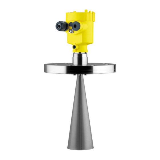
– if necessary, further certificates Principle of operation Application area The VEGAPULS SR 68 is a radar sensor for continuous measurement of bulk solids also under difficult process conditions. It is particularly suitable for level measurement in high silos and large bunkers. -
Page 12: Accessories And Replacement Parts
PACTware with VEGA-DTM is required. You can find further information in the operating instructions "Interface adapter VEGACONNECT" (Document-ID 32628). The VEGADIS 81 is an external display and adjustment unit for VEGA VEGADIS 81 plics sensors. - Page 13 The antenna impedance cone is used for optimum transmission of microwaves and for sealing against the process. You find further information in the operating instructions "Antenna impedance cone VEGAPULS 62 and 68" (Document-ID 31381). VEGAPULS SR 68 • 4 … 20 mA/HART two-wire...
-
Page 14: Mounting
Proceed as follows: Clamp VEGAPULS SR 68 with the flange, e.g. in a bench vice 2. Hold the connection piece (3) with a wrench on the flat surfaces (width across flats 22 mm) 3. -
Page 15: Mounting Preparations - Horn Antenna
1. Loosen the hexagon socket screws (3) on the antenna socket with an Allen wrench (size 3) 2. Remove the antenna (4) Note: The plastic cone may not be pulled out of the antenna socket. VEGAPULS SR 68 • 4 … 20 mA/HART two-wire... -
Page 16: Mounting Instructions
By turning the instrument in the connection flange or mounting boss, the polarisation can be used to reduce the effects of false echoes. The position of the polarisation is marked on the process fitting of the instrument. VEGAPULS SR 68 • 4 … 20 mA/HART two-wire... - Page 17 The optimum mounting position is on the opposite of the filling. To avoid strong pollution, the distance to the filter or dust extraction must be as big as possible. VEGAPULS SR 68 • 4 … 20 mA/HART two-wire...
- Page 18 The optimum mounting position is next to the filling. To avoid strong pollution, the distance to the filter or dust extraction must be as big as possible. VEGAPULS SR 68 • 4 … 20 mA/HART two-wire...
- Page 19 4 Mounting Fig. 10: Mounting of the radar sensor with inflowing medium Socket The socket piece should be dimensioned in such a way that the antenna end protrudes slightly out of the socket. VEGAPULS SR 68 • 4 … 20 mA/HART two-wire...
- Page 20 When using a swivelling holder, keep in mind that the distance between antenna and socket gets smaller as the inclination of the sensor increases. Additional false reflections may be generated which can influence the measuring result at close range. VEGAPULS SR 68 • 4 … 20 mA/HART two-wire...
- Page 21 Fig. 13: Distance between antenna and socket with horn antenna Fig. 14: Distance between antenna and socket with parabolic antenna If the medium has good reflective properties, VEGAPULS SR 68 with horn antenna can also be mounted on a longer socket piece.
- Page 22 In a cylindrical silo with conical outlet mounting is carried out on a socket. It should be positioned on one third up to the half of the vessel radius. VEGAPULS SR 68 • 4 … 20 mA/HART two-wire...
- Page 23 If mounting in the centre of the silo is not possible, the sensor can be directed to the vessel center by using the optional swivelling holder. The following description shows a simple way to determine the required angle of inclination. VEGAPULS SR 68 • 4 … 20 mA/HART two-wire...
- Page 24 4 Mounting Fig. 17: Proposal for installation after orientation VEGAPULS SR 68 The angle of inclination depends on the vessel dimensions. It can be easily checked with a suitable level or water leve on the sensor. The following chart specifies the distance "a" between installation position and vessel centre dependent on the measuring distance for inclination angles of 2°...
- Page 25 If there are agitators in the vessel, a false signal suppression should be carried out with the agitators in motion. This ensures that the interfering reflections from the agitators are saved with the blades in different positions. VEGAPULS SR 68 • 4 … 20 mA/HART two-wire...
- Page 26 Fig. 20: Radar sensors on traverse crane Information: Keep in mind that for these applications, the sensors are designed for relatively slow level changes. When using VEGAPULS SR 68 on a movable bracket, the max. measuring rate must be observed (see chapter "Technical data").
- Page 27 If the radar sensor is mounted very close to a heavily structured vessel wall, considerable false reflections can be generated. Hence the sen- VEGAPULS SR 68 • 4 … 20 mA/HART two-wire...
- Page 28 Fig. 23: Mounting of VEGAPULS SR 68 in multiple chamber silos Fig. 24: Orientation of VEGAPULS SR 68 for emptying in the silo center Dust layers To avoid strong buildup and dust in the antenna system, the sensor should not be mounted directly at the dust extraction of the vessel.
- Page 29 Fig. 26: Purging air connection with parabolic antenna The practice has shown that a pressure of approx. 0.2 … 1 bar provides a sufficient air flow (see diagram in chapter "Technical data", "Purging air connection". VEGAPULS SR 68 • 4 … 20 mA/HART two-wire...
-
Page 30: Connecting To Power Supply
(e. g. 1 nF, 1500 V). The low-frequency potential equalisation currents are thus suppressed, but the protective effect against high frequency interfer- ence signals remains. VEGAPULS SR 68 • 4 … 20 mA/HART two-wire... -
Page 31: Connecting
4. Remove approx. 10 cm (4 in) of the cable mantle, strip approx. 1 cm (0.4 in) of insulation from the ends of the individual wires 5. Insert the cable into the sensor through the cable entry VEGAPULS SR 68 • 4 … 20 mA/HART two-wire... - Page 32 7. Check the hold of the wires in the terminals by lightly pulling on them 8. Connect the screen to the internal ground terminal, connect the outer ground terminal to potential equalisation VEGAPULS SR 68 • 4 … 20 mA/HART two-wire...
-
Page 33: Wiring Plan, Single Chamber Housing
The following illustrations apply to the non-Ex as well as to the Ex-ia version. Electronics compartment 4...20mA 6 7 8 Fig. 30: Electronics compartment, double chamber housing Internal connection to the connection compartment For display and adjustment module or interface adapter VEGAPULS SR 68 • 4 … 20 mA/HART two-wire... - Page 34 - Radio module PLICS- MOBILE Status SIM-Card Test Fig. 32: Connection compartment radio module PLICSMOBILE Voltage supply You can find detailed information on connection in the supplementary instructions "PLICSMOBILE GSM/GPRS radio module". VEGAPULS SR 68 • 4 … 20 mA/HART two-wire...
-
Page 35: Wiring Plan, Double Chamber Housing Ex D
If an instrument with Ex-d-ia approval is used, HART multidrop op- eration is not possible. Connection compartment 4...20mA Fig. 34: Connection compartment, Ex-d double chamber housing Voltage supply, signal output Ground terminal for connection of the cable screen VEGAPULS SR 68 • 4 … 20 mA/HART two-wire... -
Page 36: Wiring Plan - Version Ip 66/Ip 68, 1 Bar
Pin 4 Black Wiring plan - version IP 66/IP 68, 1 bar Wire assignment, con- nection cable Fig. 37: Wire assignment fix-connected connection cable brown (+) and blue (-) to power supply or to the processing system Shielding VEGAPULS SR 68 • 4 … 20 mA/HART two-wire... -
Page 37: Switch-On Phase
As soon as a plausible measured value is found, the corresponding current is outputted to the signal cable. The value corresponds to the actual level as well as the settings already carried out, e.g. factory setting. VEGAPULS SR 68 • 4 … 20 mA/HART two-wire... -
Page 38: Set Up With The Display And Adjustment Module
The display and adjustment module is powered by the sensor, an ad- ditional connection is not necessary. Fig. 38: Insertion of the display and adjustment module with single chamber housing into the electronics compartment VEGAPULS SR 68 • 4 … 20 mA/HART two-wire... -
Page 39: Adjustment System
Adjustment system Fig. 40: Display and adjustment elements LC display Adjustment keys • Key functions [OK] key: – Move to the menu overview VEGAPULS SR 68 • 4 … 20 mA/HART two-wire... -
Page 40: Parameter Adjustment
"Setup", "Diagnosis" and "Additional set- tings" are described. The general parameters in these menu section are described in the operating instructions manual "Indicating and adjustment module". VEGAPULS SR 68 • 4 … 20 mA/HART two-wire... - Page 41 With this menu item, the sensor can be adapted to the applications. The adjustment possibilities depend on the selection "Liquid" or "Bulk solid" under "Medium". The following options are available when "Liquid" is selected: VEGAPULS SR 68 • 4 … 20 mA/HART two-wire...
- Page 42 – Vessel is very often filled and emptied • Vessel: – Socket available – Large agitator blades of metal – Vortex breakers, heating spirals • Process/measurement conditions: – Condensation, buildup by movement VEGAPULS SR 68 • 4 … 20 mA/HART two-wire...
- Page 43 – In outside facilities water and snow on the vessel top possible Transportable plastic tank: • Vessel: – Material and thickness different – Measurement through the vessel top • Process/measurement conditions: VEGAPULS SR 68 • 4 … 20 mA/HART two-wire...
- Page 44 If you want to measure the total height of both liquids reliably, please contact our service department or use an instrument specially de- signed for interface measurement. The following options are available when "Bulk solid" is selected: VEGAPULS SR 68 • 4 … 20 mA/HART two-wire...
- Page 45 Adjustment for all applications which are not typically level meas- urement • Sensor accepts all measured value changes within the measuring range immediately • Typical applications: – Instrument demonstration – Object recognition/monitoring (additional settings required) VEGAPULS SR 68 • 4 … 20 mA/HART two-wire...
- Page 46 To perform the adjustment, enter the distance with full and empty ves- sel, see the following example: VEGAPULS SR 68 • 4 … 20 mA/HART two-wire...
- Page 47 2. Edit the percentage value with [OK] and set the cursor to the requested position with [->]. 3. Set the requested percentage value with [+] and save with [OK]. The cursor jumps now to the distance value. VEGAPULS SR 68 • 4 … 20 mA/HART two-wire...
- Page 48 The measurement reliability equals signal strength minus noise. The higher the value, the more reliable the measurement. With a function- ing measurement, the values are > 10 dB. VEGAPULS SR 68 • 4 … 20 mA/HART two-wire...
- Page 49 In addition, the echo curve of the setup can be also displayed in the echo curve window and compared with the actual echo curve. VEGAPULS SR 68 • 4 … 20 mA/HART two-wire...
- Page 50 Check the distance to the product surface, because if an incorrect (too large) value is entered, the existing level will be saved as a false echo. The filling level would then no longer be detectable in this area. VEGAPULS SR 68 • 4 … 20 mA/HART two-wire...
- Page 51 By activating the appropriate curve, the volume percentage of the vessel is displayed correctly. If the volume should not be displayed in percent but e.g. in l or kg, a scaling can be also set in the menu item "Display". VEGAPULS SR 68 • 4 … 20 mA/HART two-wire...
- Page 52 The following table shows the default values of the instrument. De- pending on the instrument version, not all menu items are available or differently assigned: VEGAPULS SR 68 • 4 … 20 mA/HART two-wire...
-
Page 53: Saving The Parameter Adjustment Data
If the instrument is equipped with a display and adjustment module, the data in the sensor can be saved in the display and adjustment module. The procedure is described in the operating instructions VEGAPULS SR 68 • 4 … 20 mA/HART two-wire... - Page 54 If it is necessary to exchange a sensor, the display and adjustment module is inserted into the replacement instrument and the data are likewise written into the sensor via the menu item "Copy sensor data". VEGAPULS SR 68 • 4 … 20 mA/HART two-wire...
-
Page 55: Setup With Pactware
250 Ω), an additional external resistance is not necessary. This applies, e.g. to the VEGA instruments VEGATRENN 149A, VEGAMET 381, VEGAMET 391. Common Ex separators are also usually equipped with a sufficient current limitation resistance. In VEGAPULS SR 68 • 4 … 20 mA/HART two-wire... -
Page 56: Parameter Adjustment
Saving/printing the project as well as import/export functions are also part of the standard version. In the full version there is also an extended print function for complete project documentation as well as a save function for measured value VEGAPULS SR 68 • 4 … 20 mA/HART two-wire... -
Page 57: Saving The Parameter Adjustment Data
CD from the agency serving you. Saving the parameter adjustment data We recommend documenting or saving the parameter adjustment data via PACTware. That way the data are available for multiple use or service purposes. VEGAPULS SR 68 • 4 … 20 mA/HART two-wire... -
Page 58: Set Up With Other Systems
The files can be downloaded at www.vega.com/downloads under "Software". Field Communicator 375, 475 Device descriptions for the instrument are available as EDD for pa- rameter adjustment with the Field Communicator 375 or 475. VEGAPULS SR 68 • 4 … 20 mA/HART two-wire... -
Page 59: Diagnosis, Asset Management And Service
Changes in the measure- ment conditions during operation or buildup on the sensor can thus be recognized. The echo curve of the setup is stored via: VEGAPULS SR 68 • 4 … 20 mA/HART two-wire... -
Page 60: Asset Management Function
Out of specification: The measured value is unstable because the instrument specification is exceeded (e.g. electronics temperature). This status message is inactive by default. It can be activated by the user via PACTware/DTM or EDD. VEGAPULS SR 68 • 4 … 20 mA/HART two-wire... - Page 61 4-wire power supply unit F125 – Temperature of the elec- – Check ambient temperature tronics in the non-specified – Isolate electronics Unpermissi- section – Use instrument with higher ble electronics temperature range temperature VEGAPULS SR 68 • 4 … 20 mA/HART two-wire...
- Page 62 – Check level in the vessel Maintenance The following table shows the error codes and text messages in the status message "Maintenance" and provides information on causes as well as corrective measures. VEGAPULS SR 68 • 4 … 20 mA/HART two-wire...
-
Page 63: Rectify Faults
Check the 4 … 20 mA Connect a multimeter in the suitable measuring range according to signal the wiring plan. The following table describes possible errors in the current signal and helps to remove them: VEGAPULS SR 68 • 4 … 20 mA/HART two-wire... - Page 64 "Hold value" • In case of a too low level indication, the reason could be a line resistance that is too high VEGAPULS SR 68 • 4 … 20 mA/HART two-wire...
- Page 65 100 % during filling signal suppression with con- densation/contamination in the close range by editing time – With bulk solids use radar sen- sor with purging air connection or flexible antenna cover VEGAPULS SR 68 • 4 … 20 mA/HART two-wire...
-
Page 66: Exchanging The Electronics Module
24 hour service hotline Should these measures not be successful, please call in urgent cases the VEGA service hotline under the phone no. +49 1805 858550. The hotline is also available outside normal working hours, seven days a week around the clock. -
Page 67: Software Update
Attach the completed form and, if need be, also a safety data sheet outside on the packaging • Please contact for the return shipment the agency serving you. You can find the agency on our home page www.vega.com. VEGAPULS SR 68 • 4 … 20 mA/HART two-wire... -
Page 68: Dismounting
Pass the instrument directly on to a spe- cialised recycling company and do not use the municipal collecting points. These may be used only for privately used products according to the WEEE directive. VEGAPULS SR 68 • 4 … 20 mA/HART two-wire... -
Page 69: Supplement
The measured quantity is the distance between process fitting of the sensor and product surface. The reference plane is the seal surface on the hexagon or the lower side of the flange. VEGAPULS SR 68 • 4 … 20 mA/HART two-wire... - Page 70 ≤ 3.6 mA; ≤ 10 mA for 5 ms after switching on Load see load diagram under Power supply Damping (63 % of the input variable), 0 … 999 s adjustable VEGAPULS SR 68 • 4 … 20 mA/HART two-wire...
- Page 71 ±3 mm/10 K relating to the max. measuring range or max. 10 mm Additional deviation through electromag- < ±50 mm netic interference acc. to EN 61326 Default values, can be assigned individually VEGAPULS SR 68 • 4 … 20 mA/HART two-wire...
-
Page 72: Ambient Conditions
90 % of the final value (IEC 61298-2). Outside the specified beam angle, the energy of the radar signal has a level which is reduced by 50 % (-3 dB) EIRP: Equivalent Isotropic Radiated Power VEGAPULS SR 68 • 4 … 20 mA/HART two-wire... - Page 73 Ʋ opening pressure 0.5 bar (7.25 psig) Ʋ Nominal pressure stage PN 250 Electromechanical data - version IP 66/IP 67 and IP 66/IP 68; 0.2 bar Options of the cable entry VEGAPULS SR 68 • 4 … 20 mA/HART two-wire...
- Page 74 W x H = 7 x 13 mm Adjustment elements 4 keys Protection rating Ʋ unassembled IP 20 Ʋ mounted into the housing without IP 40 cover Materials Ʋ Housing Ʋ Inspection window Polyester foil VEGAPULS SR 68 • 4 … 20 mA/HART two-wire...
- Page 75 Protection class Approvals Instruments with approvals can have different technical data depending on the version. The prerequisites for maintaining the protection rating are a suitable cable as well as correct mounting. VEGAPULS SR 68 • 4 … 20 mA/HART two-wire...
-
Page 76: Dimensions
11 Supplement For that reason the associated approval documents of these instruments must be carefully noted. They are part of the delivery or can be downloaded under www.vega.com and "VEGA Tools" as well as under "Downloads" and "Approvals". 11.2 Dimensions The following dimensional drawings represent only an extract of all possible versions. - Page 77 ~ 150 mm (4.13") (5.91") ø 84 mm ø 84 mm (3.31") (3.31") M16x1,5 M20x1,5 M20x1,5 M20x1,5/ ½ NPT Fig. 59: Housing versions in protection IP 66/IP 68 (1 bar) - with integrated display and adjustment module the housing is 9 mm/0.35 in higher Single chamber version Double chamber version VEGAPULS SR 68 • 4 … 20 mA/HART two-wire...
- Page 78 (3.15") (3.11") M16x1,5 M20x1,5 M20x1,5/ ½ NPT M20x1,5/ ½ NPT Fig. 61: Housing versions in protection IP 66/IP 68 (1 bar) - with integrated display and adjustment module the housing is 9 mm/0.35 in higher Single chamber version, electropolished Single chamber version, precision casting Double chamber version, precision casting VEGAPULS SR 68 • 4 … 20 mA/HART two-wire...
- Page 79 3.94" ø1.58" 1½" 4.72" ø1.89" 2" 8.50" ø2.95" 3" 16.93" ø3.74" 4" Fig. 62: VEGAPULS SR 68, horn antenna in threaded version Standard With temperature adapter up to 250 °C VEGAPULS SR 68 • 4 … 20 mA/HART two-wire...
- Page 80 VEGAPULS SR 68, horn antenna in flange version inch 3.94" ø1.58" 1½" ø40 1½" 4.72" ø1.89" 2" ø48 2" 8.50" ø2.95" 3" ø75 3" 16.93" ø3.74" 4" ø95 4" Fig. 63: VEGAPULS SR 68, horn antenna in flange version Standard With temperature adapter up to 250 °C VEGAPULS SR 68 • 4 … 20 mA/HART two-wire...
- Page 81 1½" 2" 4.72" ø 1.89" 8.50" ø 2.95" 3" 4" 16.93" ø 3.74" Fig. 64: VEGAPULS SR 68, horn antenna and swivelling holder Standard With temperature adapter up to 250 °C VEGAPULS SR 68 • 4 … 20 mA/HART two-wire...
- Page 82 11 Supplement VEGAPULS SR 68, parabolic antenna and swivelling holder Fig. 65: VEGAPULS SR 68, parabolic antenna and swivelling holder Standard With temperature adapter up to 200 °C VEGAPULS SR 68 • 4 … 20 mA/HART two-wire...
- Page 83 Les lignes de produits VEGA sont globalement protégées par des droits de propriété intellec- tuelle. Pour plus d'informations, on pourra se référer au site www.vega.com. VEGA lineas de productos están protegidas por los derechos en el campo de la propiedad indus- trial. Para mayor información revise la pagina web www.vega.com.
- Page 84 35 Reset 52 Error messages 60 Event memory 59 Service hotline 66 Shielding 30 False signal suppression 50 Socket 19 Fault rectification 63 Status messages 60 Functional principle 11 Storage 12 VEGAPULS SR 68 • 4 … 20 mA/HART two-wire...
- Page 85 INDEX Subsurface enclosure 27 Type plate 10 Vessel form 46 Vessel height 46 Vessel installations 25 Vessel insulation 26 Voltage supply 30 VEGAPULS SR 68 • 4 … 20 mA/HART two-wire...
- Page 86 Notes VEGAPULS SR 68 • 4 … 20 mA/HART two-wire...
- Page 87 Notes VEGAPULS SR 68 • 4 … 20 mA/HART two-wire...
- Page 88 Subject to change without prior notice © VEGA Grieshaber KG, Schiltach/Germany 2013 VEGA Grieshaber KG Phone +49 7836 50-0 Tel: +44 (0)191 490 1547...
Need help?
Do you have a question about the VEGAPULS SR 68 and is the answer not in the manual?
Questions and answers