IDEAL Touch Installation Manual
Thermostat & transceiver combi
Hide thumbs
Also See for Touch:
- User manual (30 pages) ,
- Installation manual (18 pages) ,
- User manual (22 pages)
Advertisement
Quick Links
Class V when used in isolation. Class VI when used with an outside sensor, Class VIII when used with more than 2 zones.
Contribution to seasonal space heating energy efficiency 3% (Class V), 4% (Class VI), 5% (Class VIII).
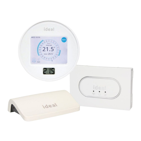
CONTENTS
A. Touch Thermostat
B. Mounting Bracket Cover
C. Mounting Bracket
D. Desktop stand
E. Transceiver
F. Batteries (AA)
G. Screws & Plugs
H. Quick Start Guide
I. SAP Registration Label
June 2017
215407 A02
THERMOSTAT & TRANSCEIVER COMBI
INSTALLATION GUIDE
A
D
E
G
H
QUICK START GUIDE
Logic Combi C / Vogue GEN2 Combi
For User & Installation Guide please visit www.idealboilers.com
INSTALLATION
1. Isolate electrical power to the
boiler.
2. Remove the blanking plate by
inserting flat blade screwdriver
into slot situated centrally at
bottom of blanking plate.
3. Remove link wire plug & keep in
a safe place.
4. Connect the transceiver
electrical plug.
5. Locate and push the transceiver
assembly into the boiler.
6. Insert only 3 batteries into the
Thermostat.
7. Turn electrical power back on
to the boiler and immediately
insert the fourth battery into the
Thermostat.
8. Hold the thermostat
approximately 2
metres away from
the boiler and
"CONNECTING TO
BOILER" will be
displayed on your
screen.
In the unlikely event that commissioning is unsuccessful (e.g. central heating
will not switch on or will not switch off), electrically isolate the boiler,
remove 1 battery and repeat from step 6.
B
C
I
Blanking
Plate
Slot
Transceiver
9. After approximately
10. "Set System Date" will
60 seconds "Set
be displayed on your
System Time" will be
screen. Use up and
displayed on your
down arrows to set
screen. Use up and
the date. Once date is
down arrows to set
set press "DONE".
the time. Once time is
set press "DONE"
F
IDEAL BOILERS LTD
Model Name:
Touch (Single Zone)
Model Qualifier:
ErP Class V or ErP Class VI
I certify that this boiler is connected to a weather
compensation control as indicated:
Touch enhanced load compensator (Class V)
Touch enhanced load compensator & OS2 weather
compensator temperature sensor (Class VI)
These products are compatible with the boiler and
provide
compensation
control
that
has
been
permanently
enabled.
The
boiler
has
been
commissioned in accordance with the manufacturer
instructions which have been supplied to the
householder. The central heating temperature control
knob should normally be set in the mid-position.
Signed:
Date:
UIN 217679 A01
Advertisement

Related Manuals for IDEAL Touch


Summary of Contents for IDEAL Touch
-
Page 1: Installation Guide
Blanking 5. Locate and push the transceiver Plate assembly into the boiler. Touch enhanced load compensator & OS2 weather 6. Insert only 3 batteries into the Thermostat. compensator temperature sensor (Class VI) Slot 7. Turn electrical power back on... - Page 2 INSTALLATION 1. Isolate electrical power to the boiler. 2. Remove the blanking plate by inserting flat blade screwdriver into slot situated centrally at bottom of blanking plate. 3. Remove link wire plug & keep in a safe place. 4. Connect the transceiver electrical plug. 5.
- Page 3 LOCATION GUIDELINES For correct wireless communication between your boiler and the Touch Thermostat there must be: • Less than 20 metres • No more than 2 walls and 1 ceiling • No large metallic objects (e.g. American fridge/freezer) • No large mirrors or windows •...
- Page 4 Dispose of the batteries according to the local statutory requirements and not with the usual domestic refuse. Ideal Boilers Ltd. P.O. Box 103, National Avenue, Kingston upon Hull, HU5 4JN Consumer Helpline T: 01482 498660 Technical Helpline T: 01482 498663...
Need help?
Do you have a question about the Touch and is the answer not in the manual?
Questions and answers