Advertisement
Advertisement
Table of Contents

Related Manuals for IDEAL Halo Combi RF


Summary of Contents for IDEAL Halo Combi RF
-
Page 3: Safety Information
Halo plus installation details please go to www.idealboilers.com The Ideal Halo Combi RF is a wireless PRT that is paired with the Halo Smart Interface installed in the boiler. The Halo Smart Interface plugs into the front aperture on the boiler and communicates to the boiler via OpenTherm. -
Page 4: Kit Contents
A. KIT CONTENTS 1. Ideal Halo Combi RF 2. Rear housing 3. Trim plate display unit 4. Desk stand 5. Smart Interface 6. Installation guide Model Name: Halo Combi RF Model Qualifier: ErP Class V or ErP Class VI I certify that this boiler is connected to a... -
Page 5: Location Guidelines
If the distance between the Halo and Smart Interface is above 30 metres or the install location is challenging, consider using the Ideal Zigbee Booster (Product Code: 221132) or mounting the Smart Interface externally to the boiler using a bracket (Product Code: 220366). - Page 6 C. INSTALLATION OF THE HALO The Halo can be either wall mounted or desk mounted. Wall mounting the Halo If there are any concerns regarding signal strength and location of the wall mounted Halo it is advisable to pair the control (section E) and check signal strength before fixing to the wall. 2.
- Page 7 Desk mounting the Halo 1. The Halo has an integrated rear housing and desk 2. Insert the 4 AA batteries provided into the front stand. housing of the Halo. Pay close attention that the orientation of the batteries is as indicated in the housing.
- Page 8 D. INSTALLATION OF THE SMART INTERFACE To install the Halo Smart Interface into a new boiler with serial letter code AFQ (found on the data plate) follow the steps below. For further details on the compatibility of older boilers and how to install the Smart Interface into a bracket and wire into the boiler please go to www.idealboilers.com Frost stat Room stat/...
- Page 9 Blanking plate Link wire plug 5. Locate the blanking plate on the front of the boiler 6. Remove link wire plug and keep and remove carefully with a small flat bladed in a safe place. screwdriver. 7. Connect the plug on the Halo Smart Interface to 8.
- Page 10 10. Check the Smart Interface connection to the boiler 9. Switch on the boiler, the Halo Smart Interface will by pressing the Override button. The Override LED power up and begin setup, this can take up to 90 should be green and the boiler will fire. Press the seconds.
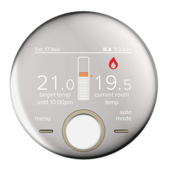
- Page 11 Sat, 17 Nov 9:33pm stage, if not changed this will default to the Ideal Boilers Customer Service number. Zigbee icon 7. The home screen will be displayed showing the current and target temperature and the temperature bar.
- Page 12 Red flashing - Pairing † Only applicable for Halo Combi Red flashing then orange - Zigbee network deletion Wi-Fi not Halo Combi RF. Orange for 30s - Factory reset * Override and failsafe only active when communication is lost Override...
-
Page 13: Advanced Settings
Automatically move to daylight saving. Frost protection The temperature that will be used to protect your home when the thermostat is off. Can be set 5°C. Service phone number Ideal Boilers Opportunity to input Installer contact number for service reminders. number... -
Page 14: Commissioning Checklist
COMMISSIONING CHECKLIST When the Halo is set up use this commissioning checklist to check and complete the install. Description Confirmed Zigbee LED on Smart Interface Use the “Identify” function to confirm successful pairing has flashes green taken place. Short press on the Pair button on the Smart Halo home screen flashes to Interface. -
Page 15: Troubleshooting
TROUBLE SHOOTING Check Smart Interface is securely plugged into boiler aperture. No power LED on Smart Interface Check boiler power is on. Boiler fails to fire when Check the target temperature is above current temperature. increasing target Check Smart Interface power LED is green. temperature on the Check Smart Interface is securely plugged into boiler aperture. - Page 16 Hereby, Ideal Boilers Ltd declares that this device (model 222140) is in compliance with: Directive 2014/53/EU. The full text of the EU declaration of conformity is available at the following internet address www.idealboilers.com Ideal Boilers Ltd National Avenue RF frequency: 2405 –2480MHz Hull, HU5 4JN Max.
Need help?
Do you have a question about the Halo Combi RF and is the answer not in the manual?
Questions and answers