Advertisement
USER GUIDE
RF electRo-mechanical timeR
& RF Room theRmostat
When replacing any part on this appliance, use only spare parts that you can be
assured conform to the safety and performance specification that we require.
Do not use reconditioned or copy parts that have not been clearly authorised by ideal.
Advertisement
Table of Contents

Related Manuals for IDEAL RF


Summary of Contents for IDEAL RF
- Page 1 USER GUIDE RF electRo-mechanical timeR & RF Room theRmostat When replacing any part on this appliance, use only spare parts that you can be assured conform to the safety and performance specification that we require. Do not use reconditioned or copy parts that have not been clearly authorised by ideal.
-
Page 2: Table Of Contents
CONTENTS RF Electro-Mechanical Timer .........4 RF Room Thermostat ..........5 Room Temperature ..........6 Setting the time............7 Timed/On/Off ............8 Setting the Central Heating On/Off Times ....9 Fault Help ............10,11 Battery Replacement ..........12 The national regulations and respective safety instructions are to be observed. -
Page 3: Rf Electro-Mechanical Timer
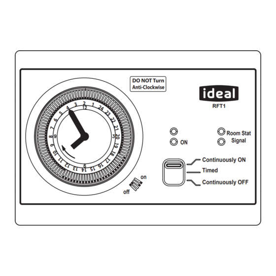
RF Electro-Mechanical Timer Suitable for the following products: Logic+ Combi Logic Code Combi & RF Room Thermostat Logic Combi Logic Code Combi ES Logic Combi E Logic Combi ES DO NOT Turn Anti-Clockwise RFT1 Room Stat Signal Continuously ON Timed Continuously OFF ºC... - Page 4 Continuously OFF On/Timed/Off Switch Note. The heat demand indicator will be illuminated whenever both the timer and room thermostat indicate that central heating is required. Note. RF signal strength light illuminates green for good signal and red for a poor signal.
-
Page 5: Room Thermostat
Room Thermostat Frost Protection Signal Operation Strength Indication Battery Indication Actual Temperature (standard display) ºC (Set Temperature shown when knob rotated) Temperature Setting Knob Note. If the low battery symbol is visible or the display is blank then replace the batteries. Frost Protection Operation will occur if the Room Temperature is less than 5ºC. -
Page 6: Room Temperature
Room Temperature To set the Room Temperature, rotate the knob until the desired temperature is shown on the display. ºC Temperature Setting Knob... -
Page 7: Setting The Time
Setting the Time The outer dial should be set to the current time. Rotate the dial slowly in a clockwise direction, until the correct hour is aligned with the arrow printed on the dial. Note that the outer dial is printed with 24 hour clock. 8.00 am = 8 on the dial. - Page 8 Timed, Continuously On and Continuously Off Operation To set the timer for Continuously On, Timed or Continuously Off operation, slide the On/Timed/Off switch into the desired position. DO NOT Turn Anti-Clockwise RFT1 Room Stat Signal Continuously ON Timed Continuously OFF On/Timed/Off Switch...
-
Page 9: Setting The Central Heating On/Off Times
Setting the Central Heating On/Off Times Set Tappets to outer edge for ON periods Set Tappets to inner edge for OFF periods Tappets set to OFF period DO NOT Turn Anti-Clockwise RFT1 Room Stat Signal Continuously ON Timed Continuously OFF Tappets set to ON period... -
Page 10: Fault Help
Re-position room thermostat. Change the batteries in the room thermostat. Replace both the RF Timer and the RF Room Thermostat for a new pair. -
Page 11: Fault Help
Re-position room thermostat. Change the batteries in the room thermostat. Replace both the RF Timer and the RF Room Thermostat for a new pair. -
Page 12: Battery Replacement
If the batteries are not replaced and no signal is received by the receiver the red room stat signal light will be illuminated on the boiler mounted RF Timer. After 1 hour the boiler will operate in “Emergency Mode” with a continuous, but reduced temperature until the batteries are replaced. - Page 16 April 2014 UIN 208937 A02 Ideal Stelrad Group pursues a policy of continuing improvement in the design and performance of its products. The right is therefore reserved to vary specification without notice. Ideal Boilers Ltd., P.O. Box 103, National Ave, Kingston Upon Hull, HU5 4JN.
Need help?
Do you have a question about the RF and is the answer not in the manual?
Questions and answers