
Related Manuals for LDG LDG Z-100Plus


Summary of Contents for LDG LDG Z-100Plus
- Page 1 Z-100PLUS OPERATIONS MANUAL MANUAL REV A LDG Z-100Plus 100-Watt Automatic Tuner LDG Electronics 1445 Parran Road St. Leonard MD 20685-2903 USA Phone: 410-586-2177 Fax: 410-586-8475 ldg@ldgelectronics.com www.ldgelectronics.com PAGE 1...
-
Page 2: Table Of Contents
Application Information Mobile Operation MARS/CAP Coverage Optional Internal Battery Installation Icom Interfacing Yaesu Interfacing Theory of Operation The LDG Z-100Plus A Word About Tuning Etiquette Care and Maintenance Technical Support Two-Year Transferrable Warranty Out Of Warranty Service Product Feedback PAGE 2... -
Page 3: Introduction
INTRODUCTION LDG pioneered the automatic, wide-range switched-L tuner in 1995. From its laboratories in St. Leonard, Maryland, LDG continues to define the state of the art in this field with innovative automatic tuners and related products for every amateur need. -
Page 4: Specifications
SPECIFICATIONS 0.1 to 125 watts SSB, CW, and digital modes. Latching relays for ultra-low power operation. 2,000 memories for instantaneous frequency and band changing. 7 to 18 Volts DC, 100 mA. Virtually zero current when not tuning. Optionally internal battery powered, 7-18VDC 1.8 to 54.0 MHz continuous frequency coverage. -
Page 5: Getting To Know Your Z-100Plus
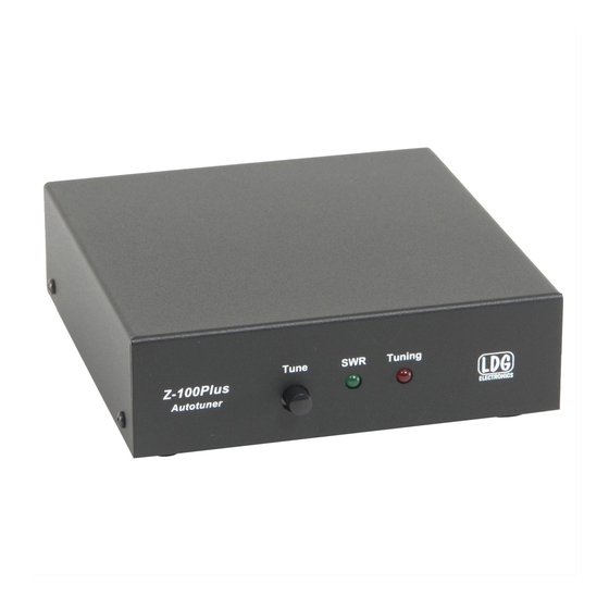
GETTING TO KNOW YOUR Z-100PLUS Your Z-100Plus is a quality, precision instrument that will give you many years of outstanding service; take a few minutes to get to know it. Tuning is performed when the Tune button is pushed on the front of the Z-100Plus and held for one second. -
Page 6: Rear Panel
Rear Panel The rear panel of the Z-100Plus features five connectors. Antenna connector: Connect the 50-ohm coax antenna feedline to this standard SO-239 connector. GND connector (wing nut): Connect to antenna system ground. Transmitter connector: Connect a 50-ohm coax jumper cable from this standard SO-239 connector to the ANT jack on the back of the transceiver. -
Page 7: Installation
(Field Day, for example), you must protect it from the rain. The Z-100Plus is designed for use with coax-fed antennas. If use with longwires or ladder-line-fed antennas is desired, an external balun is required. The LDG RBA-4:1 or RBA-1:1 is ideal, depending on the antenna and transmission line used. -
Page 8: Operation
OPERATION Basic Tuning Operation The Z-100Plus is operated from the front panel TUNE button on the Z-100Plus itself . Two types of tuning cycles are available; a memory tuning cycle and a full tuning cycle. The memory tuning cycle attempts to tune quickly based on having previously tuned on the present frequency selection. -
Page 9: Initiate A Memory Tune Cycle
Initiate a Memory Tune Cycle: To initiate a memory tuning cycle, key the transmitter, then press and hold the Tuning button on the front of the Z-100Plus until the Tuning LED lights up, then release. A memory tuning cycle will begin. Force a Full Tune Cycle: Sometimes, if you are transmitting on a previously tuned frequency, performing a memory recall tune will find a stored match that is acceptable, but is not as optimal as could be. -
Page 10: Status Indicators
Status Indicators The SWR LED and Tuning LED are both used to indicate operating modes, tuning status, and error codes. The following table lists the LED status codes and their meaning. LED Indication Meaning Tuning LED on. Tuner is tuning. Tuning LED goes out, Tuner has completed a tuning cycle;... -
Page 11: Mars/Cap Coverage
MARS/CAP Coverage The Z-100Plus provides continuous tuning coverage over its specified range; not just in the ham bands. This makes it useful for MARS or CAP operation, or any other legal HF operation. Optional Internal Battery Installation The Z-100Plus is designed to allow the user to install his own internal battery pack. The internal battery must be between 7 and 18V DC. -
Page 12: Icom Interfacing
Icom Interfacing When interfacing the Z-100Plus with AH-3 and AH-4 compatible Icom radios (IC-706, IC- 7000, for example), the Z-100Plus may be operated from the radio’s TUNER/CALL button. Push the TUNER/CALL button momentarily to toggle the bypass of the Z-100Plus. Push and hold the TUNER/CALL button for 2 seconds to initiate a memory tuning cycle. - Page 13 Simple tuners use variable capacitors and inductors; the operator adjusts them by hand while observing reflected power on the SWR meter until a minimum SWR is reached. The LDG Electronics Z-100Plus PAGE 13...
-
Page 14: The Ldg Z-100Plus
SWR. The tuner is a “Switched L” network, consisting of series inductors and parallel capacitors. LDG chose the L network for its minimum number of parts and its ability to tune unbalanced loads, such as coax-fed dipoles, verticals, Yagis, and, in fact, virtually any coax-fed antenna. -
Page 15: A Word About Tuning Etiquette
Send a photocopy of the receipt with the product whenever you send your product to LDG for repair. Products sent to LDG without a receipt are considered requests for out-of-warranty repair. -
Page 16: Out Of Warranty Service
Ask your shipper for a tracking number or a delivery verification receipt. This way you know the product arrived safely at LDG. Be sure to give us your email address so our shipper can alert you online when your product is en-route back to you. We regret that we are not able to provide periodic updates on the status of repairs.
Need help?
Do you have a question about the LDG Z-100Plus and is the answer not in the manual?
Questions and answers