
Subscribe to Our Youtube Channel
Related Manuals for LDG LDG-Z-100PLUS


Summary of Contents for LDG LDG-Z-100PLUS
- Page 1 Z-100PLUS OPERATIONS MANUAL MANUAL REV B LDG Z-100Plus 100-Watt Automatic Tuner LDG Electronics 1445 Parran Road St. Leonard MD 20685-2903 USA Phone: 410-586-2177 ldg@ldgelectronics.com www.ldgelectronics.com PAGE 1...
-
Page 2: Table Of Contents
Force a Full Tune Cycle: Status Indicators Application Information Mobile Operation MARS/CAP Coverage Icom Interfacing Yaesu Interfacing Theory of Operation The LDG Z-100Plus A Word About Tuning Etiquette Care and Maintenance Technical Support Two-Year Transferrable Warranty Out Of Warranty Service Product Feedback PAGE 2... -
Page 3: Introduction
INTRODUCTION LDG pioneered the automatic, wide-range switched-L tuner in 1995. From its laboratories in St. Leonard, Maryland, LDG continues to define the state of the art in this field with innovative automatic tuners and related products for every amateur need. -
Page 4: Specifications
SPECIFICATIONS • 0.1 to 125 watts SSB and CW; 50 watts on PSK and digital modes. • Latching relays for ultra-low power operation. • 2,000 memories for instantaneous frequency and band changing. • 7 to 18 Volts DC, 100 mA. Virtually zero current when not tuning. •... -
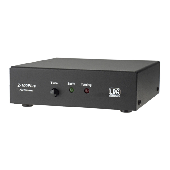
Page 5: Getting To Know Your Z-100Plus
GETTING TO KNOW YOUR Z-100PLUS Your Z-100Plus is a quality, precision instrument that will give you many years of outstanding service; take a few minutes to get to know it. Tuning is performed when the Tune button is pushed on the front of the Z-100Plus and held for one second. -
Page 6: Rear Panel
Rear Panel The rear panel of the Z-100Plus features five connectors. Antenna connector: Connect the 50-ohm coax antenna feedline to this standard SO-239 connector. GND connector (wing nut): Connect to antenna system ground. Transmitter connector: Connect a 50-ohm coax jumper cable from this standard SO-239 connector to the ANT jack on the back of the transceiver. -
Page 7: Installation
(Field Day, for example), you must protect it from the rain. The Z-100Plus is designed for use with coax-fed antennas. If use with longwires or ladder-line-fed antennas is desired, an external balun is required. The LDG RBA-4:1 or RBA-1:1 is ideal, depending on the antenna and transmission line used. -
Page 8: Operation
OPERATION Basic Tuning Operation The Z-100Plus is operated from the front panel TUNE button on the Z-100Plus itself . Two types of tuning cycles are available; a memory tuning cycle and a full tuning cycle. The memory tuning cycle attempts to tune quickly based on having previously tuned on the present frequency selection. -
Page 9: Initiate A Memory Tune Cycle
Initiate a Memory Tune Cycle: To initiate a memory tuning cycle, key the transmitter, then press and hold the Tuning button on the front of the Z-100Plus until the Tuning LED lights up, then release. A memory tuning cycle will begin. -
Page 10: Status Indicators
Status Indicators The SWR LED and Tuning LED are both used to indicate operating modes, tuning status, and error codes. The following table lists the LED status codes and their meaning. LED Indication Meaning Tuning LED on. Tuner is tuning. Tuning LED goes out, Tuner has completed a tuning cycle;... -
Page 11: Mars/Cap Coverage
MARS/CAP Coverage The Z-100Plus provides continuous tuning coverage over its specified range; not just in the ham bands. This makes it useful for MARS or CAP operation, or any other legal HF operation. Icom Interfacing When interfacing the Z-100Plus with AH-3 and AH-4 compatible Icom radios (IC-706, IC-7000, for example) using the optional IC-PAC Icom interface cable, the Z-100Plus may be operated from the radio’s TUNER/CALL button. - Page 12 The output circuit of a transmitter consists of inductors and capacitors, usually in a series/parallel configuration called a “pi network”. The transmission line can be thought of as a long string of capacitors and inductors in series/parallel, and the antenna is a kind of resonant circuit. At any given RF frequency, each of these can exhibit resistance, and impedance in the form of capacitive or inductive “reactance”.
-
Page 13: The Ldg Z-100Plus
Simple tuners use variable capacitors and inductors; the operator adjusts them by hand while observing reflected power on the SWR meter until a minimum SWR is reached. The LDG Electronics Z-100Plus automates this process. -
Page 14: A Word About Tuning Etiquette
As with any modern electronic device, the Z-100Plus can be damaged by temperature extremes, water, impact, or static discharge. LDG strongly recommends the use of a good quality, properly installed lightning arrestor in the antenna lead. -
Page 15: Technical Support
OUT OF WARRANTY SERVICE Any time a product fails after the warranty, LDG wants to help you get it fixed. Send the product to us for repair and we will determine what needs to be done. We will contact you with an estimate. -
Page 16: Product Feedback
St. Leonard, MD 20685 PRODUCT FEEDBACK We encourage product feedback! Tell us what you really think of your LDG product. In a card, letter, or email (preferred) tell us how you used the product and how well it worked in your application.
Need help?
Do you have a question about the LDG-Z-100PLUS and is the answer not in the manual?
Questions and answers