Advertisement
Quick Links
- 1 -
Introduction: The Z11 is a full featured QRP auto or semi automatic antenna tuner designed for
HF (1.8 to 30 MHz) transceivers using between 0.1 to 30 watts. The tuner uses a switched "L"
configuration with 256 capacitor, 256 inductor and Hi/Lo-Z settings to provide over one hundred and
thirty thousand tuning combinations. The tuning range is 0 to 2700 pF and 0 to 20 uH. The "L"
network works great with just about any coax fed antenna (dipole, vertical, beam, etc). Users with
long wires can install a balun between the tuner and the antenna. Tuning time is between 0.1 and
3.0 seconds with the average being about 1.5 seconds.
Latching relays are used to switch tuning components into and out of the tuning circuit. These
relays will hold the tuning configuration even if power is removed from the tuner. Once a tune has
been made the tuner enters a low power mode where it only draws 0.008 amps. Placing the tuner
into Standby can further reduce this power consumption, where it draws zero amps. During tuning,
the tuner may temporarily draw up to 0.4 amps. This current draw usually only last a second or two.
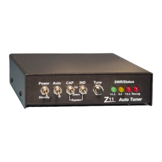
Three LEDs provide an indication of SWR while RF is present. Green indicates SWR of less than
1.5, Green/Yellow is 1.5-2.0, Yellow is 2.0-2.5, Yellow/Red is 2.5-3.0 and Red indicates more than
3.0. The fourth LED is a tuning indicator. It is lit only when the tuner is trying to find a match.
Operation: Turning on the unit with the front panel Power switch will initialize the microprocessor.
All four LEDs will flash once to indicate the power up process was initiated. Turning the unit off by
the front panel Power switch places the tuner into Standby. The tuning configuration is maintained
with the Power switch in either position.
Advertisement

Related Manuals for LDG Z11


Summary of Contents for LDG Z11
- Page 1 - 1 - Introduction: The Z11 is a full featured QRP auto or semi automatic antenna tuner designed for HF (1.8 to 30 MHz) transceivers using between 0.1 to 30 watts. The tuner uses a switched "L" configuration with 256 capacitor, 256 inductor and Hi/Lo-Z settings to provide over one hundred and thirty thousand tuning combinations.
- Page 2 9V batteries in series will provide about 14 volts DC at about 0.120 AHr. With the Z11 drawing about 0.0002 AHr per tune, the user should get about 500 tunes on a single charge. Do not use regular alkaline 9-volt batteries without regulating the power to below 15 volts.
- Page 3 A 40-meter dipole (at 30 feet) would tune just about anywhere from 3.1 to 30 MHz! We had some problems at 19 and 28 MHz finding a 1.5 match. The Z11 usually found a 2.0, and then we had to use the manual switches to get below 1.5.
- Page 4 Last Resort: As a last resort only, LDG Electronics will attempt to repair any problems. We have a flat fee of $50 plus parts to repair a Z11 (most resistors and capacitors are included in that fee). The 68HC11 chip is the most expensive at $20. Relays are $5 each. The 78L05 is $1.
- Page 5 - 5 - Building the Kit: Before getting the soldering iron out, go through all of the parts in the kit and familiarize yourself with each component and its placement. Most of the parts are common, but a few of them may be new to some builders. There are just over 100 parts and 450 solder connections, so take your time.
- Page 6 - 6 - Figure 1 L1-4 Example Figure 2 L5 - L8 Example Using the winding chart on page 5, cut a 38 inch length of wire for L8. Hold about one inch in one hand with the toroid and wind the wire around the toroid as shown in figure 1 for 33 turns. You should space the wires evenly around the toroid as you wind them.
- Page 7 - 7 - After scraping the insulation from the ends of all four wires, connect the green 2 wire to the red 1 wire and twist together. You will now have three leads: the red wire on the left, the twisted pair, and the green wire on the right.
- Page 8 - 8 - Install the .01uf 50v 8 pin SIP Capacitors, C11, 17, 19-22. Pin one is marked on the PC board with a box, and marked on the SIP capacitor with a line. Install the 78L05, U4. Note the orientation. Install the 2N3904 transistor, Q1-2.
- Page 9 - 9 - Install the relays K1-K17. Be careful not to bend the pins over pushing them in. Install the 4.5 MHz crystal, X1. Install the electrolytic capacitors, C9 10 uf radial and C18 1 uf radial. Note the polarity. Install the 14 Pin header, J3.
- Page 10 - 10 - Install a two inch length of left over #24 wire left over from winding the inductors through the hole in T1. Be sure to scrape the thermaleze coating off of the ends of the wire before soldering. Solder this from beneath the circuit board.
- Page 11 - 11 - Install the 2 SPST toggle switches (S1 & S2) in the chassis in the power and the auto positions. Remove the nut and one washer from the switch. Place the switch in the hole with the 2 prongs toward the bottom.
- Page 12 You are now ready to mount the Z11 PC board in the chassis. Install the Z11 PC board in the chassis using four screws, nylon spacers, washers and nuts. Do not drill out the holes in the PC board. Insert the four screws through the bottom of the chassis with the head on the outside next to the rubber feet you installed previously.
- Page 13 - 13 - Install a piece of insulated wire from J4 – Pin 2 – to Pin 1 of the panel mount power jack. (J4 Pin 1 is square…Pin 2 is round) Apply 11 to 14 volts DC to the power input. The center pin is positive. Turn the unit on. The LEDs should all flash once simultaneously.
Need help?
Do you have a question about the Z11 and is the answer not in the manual?
Questions and answers