Advertisement
Quick Links
SAFETY INSTRUCTIONS ........................i
SYSTEM CONFIGURATION ..................iii
EQUIPMENT LISTS................................iv
1.1 Hull Unit (FSV-253/FSV-254)..............1-1
............................................................1-7
1.3 Control Unit (FSV-2501) .....................1-9
1.4 Transceiver Unit (FSV-251) ..............1-12
1.5 Power Supply Unit (FSV-252)...........1-14
1.6 IF (Interface) Unit (FSV-8502) ..........1-15
1.7 Junction Box (FSV-2550)..................1-15
..........................................................1-15
..........................................................1-16
1.10 Attachment Flange (Option)..............1-17
1.11 Remote Controller (FSV-2504) .........1-18
2. WIRING............................................2-1
2.1 How to Connect the Units ...................2-1
2.2 Processor Unit ....................................2-2
2.3 IF Unit .................................................2-5
2.5 Transceiver Unit..................................2-9
2.6 Junction Box .....................................2-11
2.7 Raise/Lower Control Box ..................2-12
2.8 Power Supply Unit ............................2-13
2.9 Control Box Extension Box ...............2-15
3.1 How to Set the Language ...................3-1
3.2 How to Set Up the Transducer............3-3
3.3 Hull Unit Checks .................................3-4
3.4 How to Access the System Menu .......3-8
3.5 How to Adjust the Heading .................3-9
..........................................................3-10
3.8 Other System Menu Items ................3-11
All brand and product names are trademarks, registered trademarks or service marks of their respective holders.
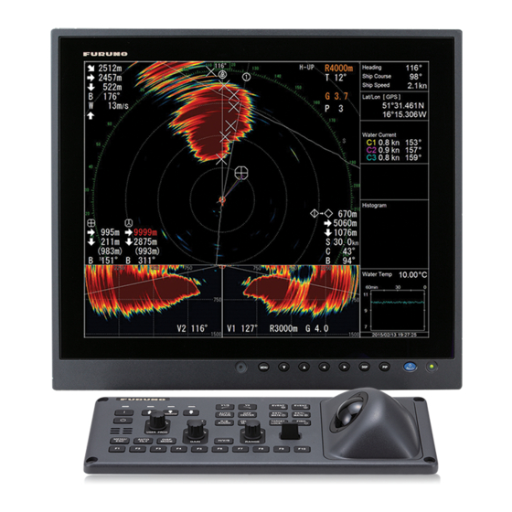
COLOR SCANNING SONAR
Model
www.furuno.com
Installation Manual
FSV-25/FSV-25S
APPENDIX 1 JIS CABLE GUIDE.....AP-1
PACKING LISTS ................................. A-1
OUTLINE DRAWINGS ........................ D-1
INTERCONNECTION DIAGRAM........ S-1
Advertisement

Related Manuals for Furuno FSV25


Summary of Contents for Furuno FSV25
-
Page 1: Table Of Contents
3.6 How to Configure the Own Ship Mark ............3-10 3.7 How to Set Up a Secondary Monitor.3-10 3.8 Other System Menu Items ....3-11 www.furuno.com All brand and product names are trademarks, registered trademarks or service marks of their respective holders. - Page 2 The paper used in this manual is elemental chlorine free. ・FURUNO Authorized Distributor/Dealer 9-52 Ashihara-cho, Nishinomiya, 662-8580, JAPAN A : MAY 2014 Printed in Japan All rights reserved. E : DEC . 09, 2016 Pub. No. IME-13440-E ( TAYA ) FSV-25/25S...
-
Page 3: Safety Instructions
High voltage exists inside the equipment, FURUNO will assume no responsibility for and a residual charge remains in capacitors several minutes after the power is turned any damage associated with improper off. - Page 4 SAFETY INSTRUCTIONS WARNING CAUTION If a steel tank is installed on a wooden Maximum speed while the transducer is or FRP vessel, take appropriate projected or being raised or lowered measures to prevent electrolytic is as below, to prevent damage to the corrosion.
-
Page 5: System Configuration
SYSTEM CONFIGURATION External External monitor monitor External USB devices Processor unit NMEA IEC61162-1 device FSV-2503 (FSV-25) FSV-2503S (FSV-25S) 12-24 VDC NMEA IEC61162-1 device Junction box FI-5002 Rectifier RU-1746B-2 External speaker Sub control unit FSV-853 100/110/115/ 220/230 VAC Control unit 1ø, 50/60 Hz FSV-2501 Remote controller FSV-2504... -
Page 6: Equipment Lists
EQUIPMENT LISTS Standard supply Name Type Code No. Remarks Control unit FSV-2501 Includes cable for control unit (5 m/10 m) Interface unit FSV-8502 Processor unit FSV-2503 For FSV-25 Processor unit FSV-2503S For FSV-25S Transceiver unit FSV-251 Power supply unit FSV-252 Junction box FSV-2550 Includes cable (5m/10 m/20 m) - Page 7 EQUIPMENT LISTS Optional supply Name Type Code No. Remarks Control unit FSV-2501 Includes cable for control unit (5 m/10 m) Sub control unit FSV-853 000-019-212 Rectifier unit RU-1746B-2 000-030-439 Remote controller FSV-2504 Includes installation materials: CP10-07401 Retraction tank OP10-40 001-269-630 For steel-hull vessels Attachment kit OP10-24...
- Page 8 EQUIPMENT LISTS This page is intentionally left blank.
-
Page 9: How To Install The System
HOW TO INSTALL THE SYSTEM Hull Unit (FSV-253/FSV-254) Note 1: The raise/lower control box on the hull unit contains a motion sensor. Handle the hull unit carefully. Note 2: Handle the transducer carefully. Rough handling can damage its sensitive components. 1.1.1 Installation considerations Decide the location of the hull unit through consultation with the dockyard and ship... - Page 10 1. HOW TO INSTALL THE SYSTEM Note 1: After you install the hull unit, make sure you install anti-vibration stays. 1300 (See "How to install the stays (anti-vibra- tion and anti-shock measures)" on page 1-6.) Note 2: Prepare a secure and firm safety Bow direction fence for the hull unit, to prevent acciden- tal injury from the moving hull unit.
- Page 11 1. HOW TO INSTALL THE SYSTEM Guidelines for installation of the retraction tank • If the keel plate on the inside of the hull is not adequate for installing the retraction tank, install a secondary keel plate. • Install the retraction tank where the keel plate and hull frame intersect. •...
- Page 12 1. HOW TO INSTALL THE SYSTEM 1.1.3 How to install the hull unit on the retraction tank Weld the retraction tank and allow sufficient time for cooling. Install the hull unit as follows: Prepare the materials and tools as shown below. Name Remarks Screw wrench...
- Page 13 1. HOW TO INSTALL THE SYSTEM Emergency switch Hex nut This switch may be remounted Spring washer on the starboard side if the Flat washer port side clearance is not Bow mark sufficient for switch operation. Hull unit flange O-ring Tank flange Hull unit Flat washer...
- Page 14 1. HOW TO INSTALL THE SYSTEM How to install the stays (anti-vibration and anti-shock measures) This measure must be done after installing the hull unit to prevent damage from vibration or impact shock to the transducer. Stays should be as sturdy as possible (75759 mm minimum recommended).
-
Page 15: Processor Unit (Fsv-2503/Fsv-2503S)
1. HOW TO INSTALL THE SYSTEM Processor Unit (FSV-2503/FSV-2503S) 1.2.1 Installation considerations When selecting a mounting location, keep the following points in mind: • Mount the unit upright (connectors facing downwards), or horizontal. • Locate the unit out of direct sunlight and away from heat sources because of heat that can build up inside the unit. - Page 16 1. HOW TO INSTALL THE SYSTEM Bulkhead installation 1. Mark locations for four self-tapping screws on the installation location. 2. Insert self-tapping screws (630, 2 pcs., supplied) at the top two screw holes, leaving approx. 5 mm of the screws exposed. 3.
-
Page 17: Control Unit (Fsv-2501)
1. HOW TO INSTALL THE SYSTEM Control Unit (FSV-2501) The control unit can be installed in a console (flush mount) or on a desktop (with KB fixture). Select a location considering the following points. • Select a location where the controls can be easily operated. •... - Page 18 1. HOW TO INSTALL THE SYSTEM Flush mount 1. Prepare a hole in the mounting location referring to outline drawing shown below. 340±0.5 351±1 4 - Pilot holes 2. Make four pilot holes for self-tapping screws (5). 3. Peel the tape from the Flush mount gasket then attach the gasket to the rear of the control unit.
- Page 19 1. HOW TO INSTALL THE SYSTEM Desktop installation, no keyboard fixture 1. Drill four mounting holes of 5 mm diameter, referring to the outline drawing at the back of this manual. 2. Fix the unit with screws (M4, 4 pcs.) from under side of the desktop. (Supply the screws locally.
-
Page 20: Transceiver Unit (Fsv-251)
1. HOW TO INSTALL THE SYSTEM Transceiver Unit (FSV-251) Select a mounting location considering that the effective length of the cable between the transceiver unit and the hull unit is 10 m (standard). The transceiver unit should be fixed to a mounting base (shipyard supply) whose dimensions are as shown in the outline drawing at the back of this manual. - Page 21 1. HOW TO INSTALL THE SYSTEM 4. Using ropes (local supply), connect the eye-bolts to the ceiling or bulkhead. Note: The transceiver sways with the ship’s roll or pitch. When the ship moves suddenly from wave impact or other causes, the transceiver unit may sway farther than the stoppers.
-
Page 22: Power Supply Unit (Fsv-252)
1. HOW TO INSTALL THE SYSTEM 5. Place the anti-vibration device cov- Hex bolt ers over the transceiver base, then (M4x8) secure the covers to the anti-vibra- tion devices using the M4x8 bolts (supplied). Power Supply Unit (FSV-252) The power supply unit (FSV-252) for the transceiver unit can be mounted in two manners, wall mount or deck mount. -
Page 23: If (Interface) Unit (Fsv-8502)
1. HOW TO INSTALL THE SYSTEM IF (Interface) Unit (FSV-8502) Refer to the outline drawing at the back of this manual for mounting dimensions. Fasten the unit with 520 self-tapping screws. If the unit is to be installed on a bulkhead, be sure that the location does not allow water to drip into the cable entrance. -
Page 24: Control Box Extension Box (Fsv-2560)
1. HOW TO INSTALL THE SYSTEM 1.8.2 How to attach the raise/lower control box to a bulkhead When using the control box extension box, the raise/lower control box can only be installed on a bulkhead. Use 4M10 bolts to fasten the raise/lower control box in po- sition. -
Page 25: Attachment Flange (Option)
1. HOW TO INSTALL THE SYSTEM 1.10 Attachment Flange (Option) When retrofitting a CSH-20 or FSV-24/30/35 hull unit on a steel hull, an attachment flange must be used. Choose the correct flange from the table below, using the length of the pre-installed tank to determine the raising height. Raising Flange type height (mm) -
Page 26: Remote Controller (Fsv-2504)
1. HOW TO INSTALL THE SYSTEM 6. Apply a slight amount of lithium grease to the threads of the bolts to prevent scorching. Insert the bolts with washers from the retraction tank flange, and then put the flat washers and spring washers in this order from above. Fasten bolts with nuts. -
Page 27: Wiring
WIRING How to Connect the Units FSV-25 Interconnections Processor Unit FSV-2503/FSV-2503S Monitor (User supply) DVI-D/D S-LINK (5/10 m) SXGA/UXGA/WUXGA DVI-D/D S-LINK (5/10 m) DPYC-6 Monitor (User supply) 12-24 VDC SXGA/UXGA/WUXGA Sub control unit USB cable FSV-853 (Option) 10S2383 (3 m) 19S1050 (3 m) IF Unit Remote... -
Page 28: Processor Unit
2. WIRING Processor Unit Referring to the figure below, connect external units to the processor unit via the front panel of the processor unit. Make sure all cables are securely connected. IF Unit FSV-5802 Transceiver unit External monitor 19S1050, 3 m FSV-251 (SXGA, UXGA, WUXGA) IF Unit... - Page 29 2. WIRING LAN cable fabrication Choose the correct length cable from the supplied LAN cables (Type: FR-FTPC-CY, lengths: 10 m, 20 m, 30 m, 50 m, 100 m), then prepare the cables as shown below. After preparing the cable attach the modular connectors as follows. Preparing the LAN cable ends Cable jacket Inner sheath...
- Page 30 2. WIRING How to extend length of cable for external monitor If the distance from the control unit to the monitor is more than 10 m, follow the procedure below to lengthen the cable, up to 70 m. The video output is analog so use an analog monitor.
-
Page 31: If Unit
The IF unit installs between the processor unit and the transceiver unit. Connect the cables according to the diagram inscribed on the shield cover of the IF unit. JIS cables and FURUNO cables are available for the connection. To connect the JIS cables, use the larger cable holes as shown below. - Page 32 2. WIRING How to connect external KP To synchronize transmission with external sonar, make the connections shown below. Current drive KP output IF UNIT KP signal (Current drive) KP input logic switching DIP SW S3-2 Sonar ON: Rising edge OFF: Falling edge Voltage drive KP output IF UNIT KP signal (12 V)
-
Page 33: Control Unit And Remote Controller
2. WIRING Control Unit and Remote Controller Ground Connect a IV-1.25 sq. ground wire (local supply) between the ground terminal on the control unit and the ship’s ground. How to connect the remote controller Connect the optional remote controller (FSV-854) as shown below. 1. - Page 34 2. WIRING 3. Connect the remote controller cable to J2 on the control unit and use the support plate to fix the cable. Pan head screw M4×12, 3 pcs. Fix at copper tape. Support plate Rear side of the control unit (cover removed) 4.
-
Page 35: Transceiver Unit
2. WIRING Transceiver Unit 2.5.1 How to connect the IF unit CN-B103 (40 pin) TRX-10 TRX-1 (64 pin) CN-B101 CN-B102 Secure Connector cables fitting inside Secure cable cables clamp inside cable Secure clamp shielded section with steel TB-B101 clamps Transducer cable clamps Earth plate S10-20-10/20 (x 10) Processor unit (FR-FTPC-CY) - Page 36 2. WIRING 2.5.2 How to connect the transducer cables 1. Remove the transceiver unit cover. 2. Connect the cables from the transducer referring to the cable no. labeled on the chassis and connector no. labeled on each PC board. Connect the HIF connector of the cable from the junction box to the TRX board on the transceiver unit.
-
Page 37: Junction Box
2. WIRING Junction Box The junction box connects the transceiver to the hull unit using (10) S10-19 cables from the transducer (hull unit) to the junction box and (10) S10-20-5/10/20 cables from the junction box to the transceiver unit. 1. Remove the junction box cover. 2. -
Page 38: Raise/Lower Control Box
2. WIRING Raise/Lower Control Box Connect the 3 phase power cable and the transceiver unit cables (10CA10053 - marked with “Control Unit”) as shown below. Connect the transceiver Connect the transceiver cables (10CA10053) here. cables (10CA10053) here. Cover the LSW HTX indicator using Blind Seal N2.5 (included). -
Page 39: Power Supply Unit
2. WIRING Ground connection Use a ground wire (IV-8 sq., local supply) to connect to the ship’s earth. Secure the cables in the cable clamp as shown below. Transceiver unit (FSV-251) 10CA10053 10CA10028 Motion sensor, Emergency Stop button* Limit Limit Rotary Rotary TPYCY-4... - Page 40 2. WIRING Breaker settings The front panel of the power supply unit houses the breakers. Remove the protective sheet covering the lid, then open the panel to adjust the breaker settings. Voltage breakers 230V 220V 115V 110V 100V Voltage indicators For 100/110/115V input set the double breaker on the right to ON.
-
Page 41: Control Box Extension Box
2. WIRING Control Box Extension Box The raise/lower control box can be wall mounted up to 5 m away from the hull using the control box extension box. 1. Disconnect the raise/lower control box from the hull unit. 2. Connect the control box extension box to the hull unit, in the same place the raise/lower control box was originally connected. - Page 42 2. WIRING How to connect the fans to the control box extension box When using the control box extension box, the fans from the raise/lower control box must be installed in the control box extension box. Follow the procedure below. 1.
-
Page 43: Post Installation Settings
POST INSTALLATION SETTINGS How to Set the Language This equipment is shipped with English set as the default language. To change the language in which the menus are displayed, follow the procedure below. The following languages are supported: English Russian Japanese Chinese French... - Page 44 3. POST INSTALLATION SETTINGS 5. Select [Changeable] then press the left button. Initial Setting Quit : English Language Remote BOX LED : ON Menu Box Transp. : OFF TVG Monitor Transp. For service personnel: do not use : OFF Monitor Setting... Data Box...
-
Page 45: How To Set Up The Transducer
3. POST INSTALLATION SETTINGS How to Set Up the Transducer To display the distance which the transducer is protruded, the limit switch location must be entered at the processor unit. To conduct this setting, the transducer must be at full protrusion. Note: “Select”... -
Page 46: Hull Unit Checks
3. POST INSTALLATION SETTINGS Hull Unit Checks Note 1: To avoid damage to the equipment, do not transmit while dry docked. Note 2: When performing maintenance to the hull unit and checking the movement, make sure that the power is on only to the hull unit and perform all checks in test mode to avoid accident or injury. - Page 47 3. POST INSTALLATION SETTINGS How to check the hull unit 1. Turn the control unit ON. Check that the ON LED and switch are on. Retract Full protrude DOWN/STOP Half protrude Protrude and retract switches on raise/lower control box 2. Check the top of the raise/lower control box to confirm the 3.3V and UP LEDs are 3.
- Page 48 3. POST INSTALLATION SETTINGS In cases where the LEDs do not display the above values, rectify the issue using the table on the following page for reference. LED display Possible cause Remedy Displayed values do not Cabling not connected. Connect cabling correctly. change.
- Page 49 3. POST INSTALLATION SETTINGS 13. Adjust the LTX switch setting to allow clear transmission at half-protrusion by doing the following. If the retraction tank has been cut at 1212 mm, skip to step 14. 1) Use the protrude/retract controls to adjust the transducer height until the transducer face is fully protruded.
-
Page 50: How To Access The System Menu
7. With the test completed, press the display select button to show the encoder revolutions. How to Access the System Menu The system menu is used by FURUNO technicians to set up and maintain the unit. This menu should not be accessed otherwise. 3.4.1 How to display the system menu 1. -
Page 51: How To Adjust The Heading
3. POST INSTALLATION SETTINGS How to Adjust the Heading Heading correction at the hull unit When the BOW mark on the flange of the hull unit can not be directed toward ship’s bow perfectly, adjust the heading so an echo which is dead ahead appears dead ahead on the display. -
Page 52: How To Configure The Own Ship Mark
3. POST INSTALLATION SETTINGS How to Configure the Own Ship Mark Set your ship’s length and width and the position of the transducer, to accurately display the own ship mark on the screen. 1. Access the system menu (See paragraph 3.4.1). 2. -
Page 53: Other System Menu Items
3. POST INSTALLATION SETTINGS Other System Menu Items This section gives a brief explanation of menu items not previously described. 3.8.1 Interface Setting menu • [NMEA1/2/3 Baud Rate]: Set the transmission rate for the NMEA 1, NMEA 2 and NMEA 3 ports. (4800 bps, 9600 bps, 19200 bps, 38400 bps.) Priority order:NMEA1>NMEA2>NMEA3. -
Page 54: Others Menu
3. POST INSTALLATION SETTINGS 3.8.3 Others menu • [Trackball Speed]: Select the tracking speed (in menu windows only) for the trackball. (Slow, Normal, Fast) • [Hull Unit Stroke]: Select the travel of the hull unit. (1200 mm, 1600 mm) • [Error Code List]: Displays a list of error codes for easy error identification. •... -
Page 55: Appendix 1 Jis Cable Guide
EX: TTYCYSLA - 4 MPYC - 4 TTYCSLA-4 # of twisted pairs Designation type # of cores Designation type The following reference table lists gives the measurements of JIS cables commonly used with Furuno products: Cable Core Cable Core Diameter Type... -
Page 56: Appendix 2 Frp Tank Installation
Keep in mind the structural integrity and waterproofing of the vessel when fabricating a FRP tank. FURUNO takes no responsibility for the fabrication or design of the FRP. • The FRP tank flange must be as smooth as possible. Peaks and troughs should be 0.5 mm or less. - Page 57 APPENDIX 2 FRP TANK INSTALLATION 5. Insert the hull unit into the retraction tank and orient the hull unit so that the bow mark (in- scribed on the hull unit flange) points toward the ship's bow. Also, take note of the waterproofing gasket bolts holes and the flange bolt holes. Make sure all three bolt holes align.
- Page 70 24/Jul/2014 H.MAKI...
- Page 71 24/Jul/2014 H.MAKI...
- Page 72 Y.NISHIYAMA 13/Sep/2011...
- Page 73 14/Apr/2015 H.MAKI...
- Page 78 D-10...
- Page 79 D-11 27/Nov/2013 H.MAKI...
- Page 80 D-12 18/Apr/2014 H.MAKI...
- Page 81 D-13 11/Nov/2013 H.MAKI...
- Page 82 D-14...
- Page 83 D-15 22/Apr/2014 H.MAKI...
- Page 84 D-16...
- Page 85 D-17 27/Mar/2014 H.MAKI...
- Page 86 D-18 19/Jun/2014 H.MAKI...
-
Page 87: Interconnection Diagram
100/115/ DPYC-2.5 整流器 *2 220/230VAC 制御部 J2 CN-B102 送受信装置 RECTIFIER DVI1 ミドリ MS_RX-H 1φ,50/60Hz PROCESSOR UNIT TRANSCEIVER RU-1746B-2 アカ MS_RX-C FSV-2503/2503S 外部モニター UNIT DVI-D/D SLINK5M/10M アオ MS_TX-A EXTERNAL MONITOR INPUT FSV-251 IV-8sq. DPYC-6 5/10m,φ7 12-24VDC クロ MS_TX-B (SXGA,UXGA,WUXGA) ムラサキ DVI2 シロ... - Page 88 上下装置 制御器延長箱 上下動制御器 HULL UNIT CONTROL BOX XHP8 RAISE/LOWER FSV-253/254 EXTENSION BOX CONTROL BOX 10CA10028,5m FSV-2560 FSV-2530 EMERGENCY BUTTON XHP6 MOTION SENSOR CN-C101 231-205/026FUR J/P401 送受信装置 10CA10053,5/10/20m, TRANSCEIVER UNIT φ17 J/P402 FSV-251/251W 734-214FUR 10CA10027,5m LIMIT SWITCH 734-208FUR ROTARY ENCODER TB-C101 10CA10029,5m キ...
Need help?
Do you have a question about the FSV25 and is the answer not in the manual?
Questions and answers