Table of Contents
Advertisement
Quick Links
Advertisement
Table of Contents

Related Manuals for Furuno FSV-85 MARK-2


Summary of Contents for Furuno FSV-85 MARK-2
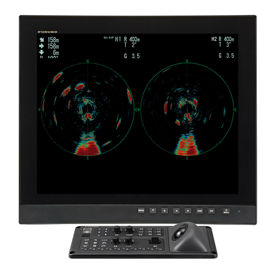
- Page 1 OPERATOR'S MANUAL COLOR SCANNING SONAR FSV-85 MARK-2 Model www.furuno.com...
- Page 2 The paper used in this manual is elemental chlorine free. ・FURUNO Authorized Distributor/Dealer 9-52 Ashihara-cho, Nishinomiya, 662-8580, JAPAN A : JUL 2021 Printed in Japan All rights reserved. B : JUN . 10, 2022 Pub. No. OME-13670-B (REFU ) FSV-85-MARK-2-70/80...
- Page 3 How to discard a used battery Some FURUNO products have a battery(ies). To see if your product has a battery, see the chapter on Maintenance. If a battery is used, tape the + and - terminals of the battery before disposal to pre- vent fire, heat generation caused by short circuit.
- Page 4 Electrical shock may result. Continued use of the equipment can cause Do not place liquid-filled containers on fire or electrical shock. Contact a FURUNO the top of the equipment. agent for service. Fire or electrical shock can result if a liquid Immediately turn off the power at the spills into the equipment.
- Page 5 WARNING LABELS Warning labels are attached to the units of the system. Do not remove the labels. If a label is missing or damaged, contact a FURUNO agent or dealer about replacement. Name: Finger Warning Label Name: Warning Label...
- Page 6 EMERGENCY STOP BUTTON ON HULL UNIT The EMERGENCY STOP button on the hull unit stops the raising or lowering of the transducer in case of an emergency. The transducer stops moving when the button is operated, a warning mes- sage appears and the transducer cannot be raised or lowered. The transducer is also stopped when the ratchet wrench in the hull unit, which is used to manually raise the transducer, is re- moved from its holder.
-
Page 7: Table Of Contents
TABLE OF CONTENTS FOREWORD ........................x SYSTEM CONFIGURATION ..................xi OPERATIONAL OVERVIEW .................1-1 1.1 Controls Overview ......................1-1 1.1.1 Control Unit ....................1-1 1.1.2 Sub control unit (option) .................1-4 1.1.3 Remote controller (Option) ................1-4 1.2 Turning the Power On/Off...................1-5 1.3 Raising/Lowering the Transducer................1-5 1.3.1 Lowering the transducer.................1-6 1.3.2... - Page 8 TABLE OF CONTENTS 2.10 How to Adjust Beam Width ..................2-20 2.11 How to Track a School of Fish ................. 2-21 2.11.1 How to select the target lock mode .............. 2-21 2.11.2 Fish mode ....................2-22 2.11.3 Target mark mode..................2-22 2.11.4 Target lock menu description ...............
- Page 9 TABLE OF CONTENTS 3.9.4 Noise limiter....................3-13 3.9.5 Reverberation....................3-14 3.9.6 Echo average ....................3-14 3.9.7 How to suppress sidelobes ................3-14 3.10 How to Adjust Beam Width..................3-15 3.11 Other Menu Items.....................3-16 3.12 Usage in Bonito and Tuna Fishing ................3-17 3.12.1 Searching .....................3-17 3.12.2 Tracking......................3-17 3.12.3 Approaching ....................3-18 3.12.4 Catching .......................3-18 SLANT MODE......................4-1...
- Page 10 TABLE OF CONTENTS 4.17 How to Measure the Speed of a School of Fish............4-25 4.17.1 How to measure the speed of a school of fish ..........4-25 4.17.2 How to delete fish marks................4-26 4.18 Event Mark ....................... 4-27 4.18.1 How to enter an event mark .................
- Page 11 TABLE OF CONTENTS 8.5 How to Load Files.......................8-6 8.5.1 How to load the setting information ..............8-6 8.5.2 How to replay setting information ..............8-7 8.6 How to Delete Files ....................8-8 MAINTENANCE .....................9-1 9.1 Preventative Maintenance ..................9-1 9.2 Hull Unit Maintenance ....................9-2 9.2.1 How to grease parts ..................9-3 9.2.2...
-
Page 12: Foreword
FOREWORD A Word the Owner of the FSV-85 MARK-2 Congratulations on your choice of the FURUNO FSV-85 MARK-2 Color Scanning Sonar. We are confident you will see why the FURUNO name has become synonymous with quality and reliabil- ity. Since 1948, FURUNO Electric Company has enjoyed an enviable reputation for quality marine electronics equipment. -
Page 13: System Configuration
SYSTEM CONFIGURATION Remote Controller FSV-854-MK-2 REMOTE CONTROLLER REMOTE CONTROLLER AD Converter Gyrocompass AD-100 NMEA0183 devices (max. five units) External KP Processor Unit FSV-8503-MK2 USB 3.0 devices (max. two units USB 2.0 devices (max. two units Sub Control Unit Switching Hub FSV-853 Speaker SEM-21Q 12-24 VDC AC/DC Power... - Page 14 SYSTEM CONFIGURATION This page is intentionally left blank.
-
Page 15: Operational Overview
OPERATIONAL OVERVIEW Controls Overview 1.1.1 Control Unit Scrollwheel Scrollwheel Left button Left button Right button Right button V2/S V1/S H/V/S H/V/S AUTO TRAIN Trackball Trackball Key/Control Description Press to turn the power on or off. Raises the transducer. If the mid protrusion key is programmed to [Fixed Position]: Lowers the transducer to half protrusion. - Page 16 1. OPERATIONAL OVERVIEW Key/Control Description Enters an event mark 1 or own ship mark (horizontal mode). EVENT Enters an event mark 2 or own ship mark (horizontal mode). EVENT Enters a target lock mark. Shows/hides the estimate mark. TARGET LOCK Shows/hides the estimate mark 1.
- Page 17 1. OPERATIONAL OVERVIEW Key/Control Description Sets the transducer tilt angle (based on sea surface). TILT Perform assigned program/function. Speaker Outputs audio for key operation, alerts and raise/lower completion. Trackball • Moves the cursor. • Highlights a menu item. Right button (short press)* •...
-
Page 18: Sub Control Unit (Option)
1. OPERATIONAL OVERVIEW 1.1.2 Sub control unit (option) The sub control unit lets you control the sonar from a remote location. Function (on control unit) Same as 1/F1 to 4/F4 key. (The program can be changed. See section 6.2.4.) Same as trackball unit on con- trol unit. -
Page 19: Turning The Power On/Off
). The lamp to the left of the power switch lights up. A beep sounds, and the display changes in the following sequence: FURUNO display mod- el display board test display (see section 9.11.2). Then the lamp beside the switch changes as below. -
Page 20: Lowering The Transducer
1. OPERATIONAL OVERVIEW 1.3.1 Lowering the transducer With the boat at the fishing ground and the power on, press the key to lower the transducer. The lamp to the left of the key flashes during lowering and the message "Lowering "... -
Page 21: Raising The Transducer
1. OPERATIONAL OVERVIEW 1.3.2 Raising the transducer Press the key to raise the transducer. The lamp to the left of the switch flashes and the message "Raising (back color: green)*" flashes on the screen while the trans- ducer is being raised. When retraction begins, the transmission is stopped and the message "TX STOPPED"... -
Page 22: Screen Brilliance And Panel Dimmer
Screen Brilliance and Panel Dimmer How to adjust the screen brilliance If your monitor is FURUNO and the monitor is connected to the processor unit via USB, you can adjust the screen brilliance from the control unit. Turn the BRILL knob clockwise to increase, or counter-clockwise to decrease, the brilliance. - Page 23 1. OPERATIONAL OVERVIEW 2. Roll the trackball to select [Others] then push the left button. 3. Click [Display Setting].
-
Page 24: Display Modes
Horizontal + Slant*, Vertical1* and Vertical 1 + Vertical 2*. *: If the FSV-85 MARK-2 is fitted with dual monitors, you can select how the picture data is shown on two displays; Dual Display or Sub Display. For details, see "2nd Monitor Setting"... -
Page 25: How To Select A Display Mode
1. OPERATIONAL OVERVIEW Display format The on-screen display area is comprised of a data display area and an echo display area. You can select one of two display formats, as indicated below. One shows the echoes with the outermost range ring as the boundary, the other shows echoes in a full-screen display. -
Page 26: Display Mode Pictures
1. OPERATIONAL OVERVIEW 1.5.2 Display mode pictures Below are typical pictures. For sake of brevity, indications and marks are not shown. Horizontal mode This mode provides 360-degree coverage around the vessel and it is useful for gen- eral search. For further details, see chapter 2. NUMERIC/ GRAPHIC DATA... - Page 27 1. OPERATIONAL OVERVIEW Slant mode, single display The Slant mode shows a 180-degree cross section, using chosen tilt angle and train setting. For further details, see chapter 4. Bottom School of fish Sea surface reflection Slant mode (single display) H and S mode This mode provides horizontal and slant modes in one of the configurations shown be- low.
-
Page 28: Software Function Keys
1. OPERATIONAL OVERVIEW V1 and V2 modes The V1 and V2 modes show a vertical slice of the bearing selected by the vertical bearing mark on the horizontal display. The vertical 2 mode provides two vertical slic- es. For further details, see chapter 3. NUMERIC/ NUMERIC/ GRAPHIC... -
Page 29: How To Adjust The Gain
1. OPERATIONAL OVERVIEW How to Adjust the Gain The GAIN knob adjusts receiver gain (sensitivity). Adjust it so fish echoes are clearly displayed with minimal noise on the screen. Too high a gain setting not only displays excess noise and makes it difficult to discriminate wanted echoes but also causes bot- tom echoes to be painted in strong colors, resulting in echoes being masked by bottom reflections. -
Page 30: How To Use The Menu
1. OPERATIONAL OVERVIEW How to Use the Menu Most operations are carried out from the menu. This section provides basic menu op- erating information. 1. Press the MENU/ESC key to open the main menu. Menu title Select QUIT with trackball and then left click to close the menu. - Page 31 1. OPERATIONAL OVERVIEW 6. Select the setting. • (Numeric) Select to increase the value then push the left-click button (or roll the scrollwheel upward). To decrease the value, select and push the left-click button (or roll the cursor scrollwheel downward). •...
- Page 32 1. OPERATIONAL OVERVIEW Pop-up menu operation Push the right-click button on the numeric/graphic data display to show the pop-up menu. These items can be accessed from the main menu. 1-18...
-
Page 33: Horizontal Mode
HORIZONTAL MODE Basic Operating Procedure Lower the transducer. • If the mid protrusion key is programmed to [Fixed Position]: Lowers the transducer to half protrusion. • If the mid protrusion key is programmed to [Any Position]: The transducer stops at desired position. Turn the power on. -
Page 34: Horizontal Display Overview
2. HORIZONTAL MODE Horizontal Display Overview 2.2.1 Horizontal mode, full-screen display The full-screen horizontal display provides a 360° picture around the boat. To display the full-screen horizontal picture, press the DISP MODE key. Net shoot data Distance run from Line connecting Target lock mark* shooting Fish... -
Page 35: Horizontal2 Mode
2. HORIZONTAL MODE 2.2.2 Horizontal2 mode The H2 mode shows one of three kinds of horizontal display combinations: Land- scape, Portrait or Inset as shown on page 12. Follow the procedure shown below to select a combination display. The zoom-out display (shown on the inset mode) can be moved by drag and drop operation and its size changed from the menu. -
Page 36: Display Range
2. HORIZONTAL MODE Display Range The RANGE control selects the Surface detection range and six ranges Range displayed on display are preset at the factory. The range selected is momentarily dis- played in large characters at the Bottom top of the screen. Range is always displayed next to “R”... -
Page 37: Tilt Angle
2. HORIZONTAL MODE Tilt Angle The tilt angle shows the direction to which the sound wave is emitted. When the sound wave is emitted horizontally, the tilt angle is said to be 0° and when vertically, 90°. The tilt angle can be set between -5° (upward) to 60° (downward), in increments of 1°. The tilt angles for horizontal 1 and horizontal 2 modes can be set independently of one an- other. - Page 38 2. HORIZONTAL MODE 2. If necessary operate the TILT control to change center tilt angle. In automatic tilt, “AUTO” is displayed at the top right corner. To disable automatic tilt, select OFF at step 1. Auto tilt is active R 400m N-UP AUTO G 10...
-
Page 39: Relation Between Bottom Echo And Tilt Angle
2. HORIZONTAL MODE 2.4.3 Relation between bottom echo and tilt angle The figure below illustrates how two schools of fish "a" and "b" are displayed on the screen using three different tilt angles. Case 1: Tilt angle 30° to 40°: This tilt angle will display the entire bottom since it is captured by the full width of the beam. -
Page 40: Tilt Angle For Surface Fish
2. HORIZONTAL MODE 2.4.4 Tilt angle for surface fish The sound emitted from the sonar transducer forms a beam with a width of approxi- mately 10° in the vertical direction (vertical beam width at -6 dB). The tilt angle indi- cates the angle between the centerline of the beam and the horizontal plane. -
Page 41: How To Measure Range And Bearing To A Target
2. HORIZONTAL MODE How to Measure Range and Bearing to a Target Operate the trackball to place the cursor on the target you want to measure the range and bearing. The range, bearing and depth to the target appear at the upper left corner of the screen. - Page 42 2. HORIZONTAL MODE 3. Press the H/V/S key to select the [S] tab. 4. Select [Sel. TVG Curve] then push the left-click button. 5. Select a curve then push the left-click button. The smaller the number, the gentler the gain change over distance. 6.
- Page 43 2. HORIZONTAL MODE 5. Select [Changeable] then push the left-click button. Current settings Select item with trackball; push left-click button to adjust. 6. Select [Near], [Middle] or [Far] as appropriate then push the left-click button to change the setting. Near: Setting range, 50 - 150 m, 10 m increments. Middle: Setting range, 300 - 500 m, 20 m increments Far: Setting range, 600 - 1000 m, 40 m increments 7.
-
Page 44: How To Adjust Strong And Weak Echoes
2. HORIZONTAL MODE How to Adjust Strong and Weak Echoes 2.7.1 The AGC function automatically reduces the receiver gain only against strong echoes such as the bottom or a large school of fish. Since the AGC function does not affect weak echoes, a small school of fish becomes easier to detect. -
Page 45: 2Nd Agc
2. HORIZONTAL MODE 2.7.3 2nd AGC While it is ideal to suppress bottom echoes with the AGC alone there are some fishing grounds where this is not possible. (The high power sonar has the advantage of long- range detection but this can also be a disadvantage, since weaker echoes may be hid- den in strong, unwanted echoes such as the bottom.) If you cannot suppress bottom echoes or sea surface reflections by the AGC function alone, use the 2ND AGC fea- ture. -
Page 46: How To Shorten Pulse Length
2. HORIZONTAL MODE Exclusive Rng S: This feature prevents use of the 2nd AGC, Post 2nd AGC in a certain area at the stern, where unwanted echoes (such as screw noise) can interfere with the 2ND AGC or Area of Post 2nd AGC feature. -
Page 47: How To Suppress Bottom And Sea Surface Reflections In Shallow Waters
2. HORIZONTAL MODE How to Suppress Bottom and Sea Surface Reflections in Shallow Waters In shallow fishing grounds with hard or rocky bottom, bottom reflections often interfere with wanted fish echoes and they can not be eliminated sufficiently with the aforemen- tioned TVG and AGC functions, especially when the Tilt is set to a larger angle in order to track schools of fish approaching within 400 m. -
Page 48: How To Reject Sonar Interference And Noise
2. HORIZONTAL MODE How to Reject Sonar Interference and Noise While observing the sonar picture, you may encounter occasional or intermittent noise and interference. These are mostly caused by on-board electronic equipment, engine or propeller noise, or electrical noise from other sonars being operated nearby. 2.9.1 How to identify the noise source To eliminate noise effectively, you should first identify the noise source as follows:... -
Page 49: Interference Rejector
2. HORIZONTAL MODE 2.9.3 Interference rejector This control is similar to the interference rejector on echo sounders and radars. It is effective for rejecting random noise and sea surface reflections in rough sea condi- tions. Set it so that noise is just eliminated. Do not use an unnecessarily high setting since it may also reject small, wanted echoes. -
Page 50: Noise Limiter
2. HORIZONTAL MODE 2.9.5 Noise limiter Weak, unwanted reflections, colored light-blue or green, are often caused by dirty wa- ter, plankton layers, or ship’s noise. The noise limiter can reduce the effects of these unwanted reflections. Raising the setting causes unwanted reflections to be displayed in colors of blue to background color. -
Page 51: Reference Bearing In Frequency Shift
2. HORIZONTAL MODE Setting between 4 and 7: Echoes are quickly displayed and afterglow remains on the screen longer as the setting is increased. 2.9.8 Reference bearing in frequency shift The reference bearing in frequency shift can be changed to avoid sonar interference and noise. -
Page 52: How To Adjust Beam Width
2. HORIZONTAL MODE 2.10 How to Adjust Beam Width The width of the horizontal beam can be adjusted from the [Beam Width] menu. 1. Press the MENU/ESC key to show the main menu. 2. Select [TX/RX Setting] then push the left-click button. 3. -
Page 53: How To Track A School Of Fish
Select one from the menu as shown in the procedure that follows. The default setting is tracking of school of fish. Speed and bearing data are re- quired.The FSV-85 MARK-2 cannot track a school of fish if the level of the echo is too weak. -
Page 54: Fish Mode
2. HORIZONTAL MODE 2.11.2 Fish mode The automatic echo target lock function automatically tracks the operator-selected school of fish. When [TILT INTERLOCK] on the [TARGET LOCK] menu (previous page) is set to [TILT & RANGE], and the tracked school of fish goes out of the zone in the range direction, the range and tilt are automatically changed according to the po- sition of the school of fish. -
Page 55: Target Lock Menu Description
2. HORIZONTAL MODE 3. Press the TARGET LOCK key. Tilt, range and vertical bearing are automatically adjusted to track the location. Us- ing the figure above as an example, the target lock mark is placed on location E. Then, the equipment remembers the location of E and automatically changes the tilt angle as the ship moves from position A through D. -
Page 56: Presentation Mode
2. HORIZONTAL MODE 2.12 Presentation Mode 2.12.1 Presentation mode description This sonar has four presentation modes, head-up, north-up, course-up and true mo- tion. Select one with [Presentation Mode] in the [Others] - [Display Setting] menu. Head-up North-up Course-up True Motion Head-up: The display is oriented toward ship’s heading. -
Page 57: How To Select A Presentation Mode
2. HORIZONTAL MODE 2.12.2 How to select a presentation mode 1. Press the MENU/ESC key to show the main menu. Quit 2. Click [Others]. Cancel 3. Click [Display Setting]. Head Up 4. Click [Presentation Mode]. North Up 5. Click desired mode. Course Up 6. -
Page 58: How To Select The Audio Sector
2. HORIZONTAL MODE 2.13.2 How to select the audio sector Select the audio sector as follows. Note that you cannot see this sector on the display. 1. Press the MENU/ESC key to show the main menu. 2. Select [Others] then push the left-click button. 3. -
Page 59: Reverberation For Audio Signal
2. HORIZONTAL MODE 2.13.4 Reverberation for audio signal You may select the length of reverberation of the audio signal, with [Reverberation] on the [Alarm & Audio] menu. The larger the value the longer the reverberation, which makes it easier to hear the audio signal. The setting range is 0 to 9 and the default setting is 0. -
Page 60: How To Relocate A School Of Fish
2. HORIZONTAL MODE More than 3° Within 3° Note 2: The echo strength which triggers the alarm can be set with [ALARM LEVEL] on the [Alarm & Audio] menu. The setting range is 0-30. This value corresponds with the 32-echo colors. To disable the alarm, select [OFF] in the procedure on the previous page. -
Page 61: How To Compare Concentration Of School Of Fish
2. HORIZONTAL MODE 2.16 How to Compare Concentration of School of Fish 2.16.1 How to compare with the fish estimate mark You can get an estimate of the volume of two schools of fish by using the two ESTI- MATE keys as follows: 1. -
Page 62: How To Compare With The Circle Cursor
2. HORIZONTAL MODE Fish estimate mark source Fish estimate Scan1 Scan1 mark source Fish estimate mark no. Scan2 Estimate mark 1 or estimate Both estimate marks displayed mark 2 displayed Note: The histogram display is redrawn five transmissions after a fish estimate mark is erased and another mark of the same number is entered soon after. -
Page 63: How To Measure The Speed Of A School Of Fish
2. HORIZONTAL MODE 2.17 How to Measure the Speed of a School of Fish To ensure a good haul, it is important to estimate the direction and speed of the school of fish before shooting the net. You can do this with the FISH key. With tidal current data and fish speed data, you can determine the timing of the net shooting more effi- ciently. -
Page 64: How To Delete Fish Marks
2. HORIZONTAL MODE This data is the latest fish mark data. Fish Mark 1 [FISH] key pressed once twice three times four times This data is the latest fish mark data. Fish Mark 2 [FISH] key pressed once twice three times four times 2.17.2 How to delete fish marks... -
Page 65: Event Mark, Own Ship Position Mark
2. HORIZONTAL MODE 2.18 Event Mark, Own Ship Position Mark The event mark is useful for finding the horizontal range, depth and bearing to a loca- tion some distance from current position. 20 such marks may be inscribed on the hor- izontal display. -
Page 66: How To Enter An Own Ship Position Mark
2. HORIZONTAL MODE 2.18.2 How to enter an own ship position mark Place the cursor close to the center of the own ship mark (transducer position) and press the EVENT key. Ten own ship position marks may be inscribed. When the ca- pacity for own ship position marks is reached the earliest own ship position mark is automatically erased. -
Page 67: Net Course Mark
2. HORIZONTAL MODE 2.20 Net Course Mark Before shooting the net, decide the shoot timing considering tide direction, distance to the school of fish and moving direction of the school of fish. Use the net course mark as a guide to decide the timing. This function requires speed and heading data. How to enter the net course mark 1. -
Page 68: Net Behavior
2. HORIZONTAL MODE 2.21 Net Behavior With connection of a net sonde, you can observe net behavior after the throwing of the net. Accurate depiction of net sonde position depends on proper setting of the distanc- es between net sonde transmitters. You can set those distances on the main menu- [Others] - [Initial Setting] - (Change confirmation window) - [Net Sonde Setting] menu. -
Page 69: Menu Items Descriptions
2. HORIZONTAL MODE 2.22 Menu Items Descriptions This section presents an overview of the horizontal display related menus not previ- ously described. Gain Setting menu Gain Control: If the amount of gain change affected with the GAIN control on the front panel is too low, change the setting to [Wide], to double the range of the control. - Page 70 2. HORIZONTAL MODE 1. Operate the trackball to select color then push the left-click button to show the col- or bar. Select color with trackball. COL: Cycles through default colors. HUE: Adjusts color tint (Setting range: 0-100(%)). SAT (Saturation): Adjusts color vividness (Setting range: 0-100(%)).
- Page 71 2. HORIZONTAL MODE To set input level versus output level, use the trackball to place the cursor on location desired and push the left-click button. Note: To restore default color setting, select [Default] on the window push the left-click button then click the [Apply] button. Picture Setting menu Smooth Echo RNG: Selects echo smoothing level in the range direction.
-
Page 72: How To Interpret The Horizontal Display
2. HORIZONTAL MODE 2.23 How to Interpret the Horizontal Display 2.23.1 Bottom and school of fish echoes Bottom echoes When the tilt angle is changed, the bottom echo illustrated below will appear on the display. When the tilt is decreased (toward 0°), the bottom trace becomes wider and weaker. - Page 73 2. HORIZONTAL MODE School of fish A school of fish appear as a mass of echoes on the screen. By this display pattern, the density of the school on the sonar beam can be found. To find distribution and center point of a school of fish, try several different tilt angles.
-
Page 74: Unnecessary Echoes
2. HORIZONTAL MODE 2.23.2 Unnecessary echoes Sea surface reflections To reduce sea surface reflections, set the tilt angle to 4° or higher, so the upper edge of the sonar beam does not hit the sea surface, or adjust near gain. When a decreased tilt is used, sea surface reflections cover a large area as illustrated below. - Page 75 2. HORIZONTAL MODE Sidelobe echoes (false echoes) An ultrasonic wave is emitted only in the direction set by the TILT control, however there are some emissions outside the main beam. These are called sidelobes. The en- ergy of the sidelobe is fairly weak but when the water is comparatively shallow and the bottom is rocky and hard, strong signals are detected by the sidelobe.
- Page 76 2. HORIZONTAL MODE This page is intentionally left blank. 2-44...
-
Page 77: Vertical Mode
VERTICAL MODE Basic Operating Procedure Lower the transducer. • If the mid protrusion key is programmed to [Fixed Position]: Lowers the transducer to half protrusion. • If the mid protrusion key is programmed to [Any Position]: The transducer stops at desired position. Lowers the transducer to full protrusion. -
Page 78: How The Vertical Mode Works
3. VERTICAL MODE How the Vertical Mode Works 3.2.1 Overview The vertical mode shows a vertical section of the horizontal display selected with the vertical bearing mark. The figure below illustrates the concept of the vertical mode, in comparison with the horizontal mode. The vertical mode helps you keep fast moving fish such as bonito and tuna within the sonar beam. -
Page 79: Vertical Indications And Marks
3. VERTICAL MODE Vertical Indications and Marks 3.3.1 Typical vertical display The vertical mode provides a vertical section of the horizontal picture. You may show the display on the right or left side of the screen in case of the vertical 1 mode. An ex- pansion mode is available to enlarge the picture. -
Page 80: Vertical Bearing Mark, Tilt Mark
3. VERTICAL MODE Note: When the settings listed below are changed, the setting value is shown at the top of the display for five seconds. The location of the setting value can be changed. Contact your dealer for details. • Gain (See section 1.7.) •... -
Page 81: Cursor Position Reference Mark
3. VERTICAL MODE 3.3.3 Cursor position reference mark The cursor position reference mark, a solid circle, is inscribed on the vertical bearing mark when the cursor is placed in the vertical display. Its purpose is to show the cor- responding cursor position on the horizontal display. It changes position with cursor position, tilt and range, and disappears when its position is no longer within the range of the horizontal display. -
Page 82: Display Range
3. VERTICAL MODE Display Range The RANGE control selects the detection range. The range selected is momentarily displayed in large characters at the top of the vertical 1 display. Range is always dis- played next to “R” at the lower part of the vertical 1 display. The default ranges are as shown below (unit: m). -
Page 83: How To Eliminate Weak Echoes
3. VERTICAL MODE How to Eliminate Weak Echoes Echoes from targets such as bottom and fish return to the transducer in order of dis- tance to them, and when we compare their intensities at the transducer face, those from nearer targets are generally stronger due to little propagation attenuation and lit- tle absorption. - Page 84 3. VERTICAL MODE TVG distance and setting This sonar has three TVG functions, Near, Medium and Far, and they mainly compen- sate for propagation loss on short, middle and long ranges respectively, centered at the ranges shown below. The higher the TVG setting the greater the amplification of echoes.
-
Page 85: How To Adjust Strong And Weak Echoes
3. VERTICAL MODE How to Adjust Strong and Weak Echoes 3.8.1 The AGC functions to automatically reduce the receiver gain only against strong echoes such as the bottom or a large school of fish. Since weak echoes remain unaf- fected, a small school of fish becomes easier to detect. Adjust it so that the AGC works only on bottom reflections. -
Page 86: 2Nd Agc
3. VERTICAL MODE 3.8.3 2nd AGC While it is ideal to suppress bottom echoes with the AGC alone there are some fishing grounds where this is not possible. (The high power sonar has the advantage of long- range detection but this can also be a disadvantage, since weaker echoes may be hid- den in strong, unwanted echoes such as the bottom.) If you cannot suppress bottom echoes or sea surface reflections by the AGC function alone, use the 2ND AGC fea- ture. -
Page 87: How To Reject Sonar Interference And Noise
3. VERTICAL MODE 2. Select [TX/RX Setting] then push the left-click button. 3. Press the H/V/S key to select the [V] tab. 4. Select [TX Pulse Length] then push the left-click button. 5. Select or then push the left-click button to change the setting. The setting range is 0-9. -
Page 88: Interference Rejector
3. VERTICAL MODE 3.9.2 Interference rejector This control is similar to the interference rejector on echo sounders and radars. It is effective for rejecting random noise and sea surface reflections in rough sea condi- tions. Set it so that noise is just eliminated. Do not use an unnecessarily high setting since it may also reject small wanted echoes. -
Page 89: Noise Limiter
3. VERTICAL MODE 3.9.4 Noise limiter Weak, unwanted reflections, colored light-blue or green, are caused by dirty water, plankton layers, or ship's noise. The noise limiter can reduce the effects of these un- wanted reflections. Raising the setting causes unwanted reflections to be displayed in colors of blue to background color. -
Page 90: Reverberation
3. VERTICAL MODE 3.9.5 Reverberation You may choose the length of reverberation for the echo signal, with [Reverberation] in the [TX/RX Setting] menu on the [V] tab. The larger the value, the lower the rever- beration effect, which makes it easier to see the echo signal. The setting range is 0-3. 3.9.6 Echo average [Echo Average] on the [Picture Setting] menu in the [V] tab adjusts echo afterglow -... -
Page 91: How To Adjust Beam Width
3. VERTICAL MODE 3.10 How to Adjust Beam Width The width of the horizontal beam can be adjusted from the [Beam Width] menu. 1. Press the MENU/ESC key to show the main menu. 2. Select [TX/RX Setting] then push the left-click button. 3. -
Page 92: Other Menu Items
3. VERTICAL MODE 3.11 Other Menu Items This section describes menu items which have not been explained yet. Gain Setting menu Gain Control: If the amount of gain change affected with the GAIN control on the front panel is too low, change the setting to [Wide], to double the range of the control. Display Setting menu Gain Offset: Adjusts gain level. -
Page 93: Usage In Bonito And Tuna Fishing
3. VERTICAL MODE Color: Select color arrangement to use. The default setting is Color 1. V-Scan Color 1 (2 to 4) Setting: Customizes colors. V-Scan Color Curve Setting: Adjusts reflected echo strength versus echo color level for currently selected color response number. Picture Setting menu Smooth Echo RNG: Selects echo smoothing level in the range direction. -
Page 94: Approaching
3. VERTICAL MODE 3.12.3 Approaching The sonar lets you view the movement of a school of fish continuously, thus you can approach a school confident of a good catch. While a flock of birds hovering over the sea surface is usually a good indication of the presence of a school of fish, the sonar can better verify the size of a school of fish. -
Page 95: Slant Mode
SLANT MODE Basic Operating Procedure Lower the transducer. • If the mid protrusion key is programmed to [Fixed Position]: Lowers the transducer to half protrusion. • If the mid protrusion key is programmed to [Any Position]: The transducer stops at desired position. Turn the power on. -
Page 96: Indications And Marks
4. SLANT MODE Indications and Marks The picture produced by the slant mode is the same as that of the half-circle sonar picture. The slant mode provides a half-circle (180°) picture, with own ship at the cen- 4.2.1 Slant mode, full-screen display To select the full-screen slant mode display, press the MODE key and select [S]. -
Page 97: Slant Mode, Combination Display
4. SLANT MODE 4.2.2 Slant mode, combination display The slant mode combination display provides the slant and horizontal pictures. The pictures can be arranged in landscape, portrait and inset. The zoom-out display shown on the inset display can be moved or you can change the size with the drag and drop operation. -
Page 98: Display Range
4. SLANT MODE Display Range The RANGE control selects the Surface detection range and six ranges Range displayed on display are preset at the factory. The range selected is momentarily dis- played in large characters at the Bottom top of the screen. Range is always displayed next to "R"... -
Page 99: Automatic Tilt
4. SLANT MODE 4.4.2 Automatic tilt The AUTO TILT key automatically scans the tilt angle within the selected width. This is useful when you want to find the center depth of a school of fish. Wide tilt angle is activated from the [Auto Tilt] in the [Others] - [Display Setting] menu. 1. -
Page 100: Auto Train
4. SLANT MODE Auto Train This feature provide automatic training of the Tx and Rx beams in left and right directions to enable search over a wide area. This feature is inopera- Train center tive when target lock is active. angle 1. -
Page 101: How To Eliminate Weak Echoes
4. SLANT MODE How to Eliminate Weak Echoes Echoes from targets such as bottom and fish return to the transducer in order of dis- tance to them, and when we compare their intensities at the transducer face, those from nearer targets are generally stronger due to little propagation attenuation and lit- tle absorption. -
Page 102: How To Adjust Strong And Weak Echoes
4. SLANT MODE TVG distance and setting This sonar has three TVG functions, Near, Medium and Far, and they mainly compen- sate for propagation loss on short, middle and long ranges respectively, centered at the ranges shown below. The higher the TVG setting the greater the amplification of echoes. -
Page 103: Near Agc
4. SLANT MODE 4.8.2 Near AGC When the water is shallow or heavily sedimented, the reflected echoes from close-in, unwanted echoes may be excessively strong. In this case, a school of fish which is displayed at between 300 m to 500 m and beyond may disappear gradually when the ship starts approaching the school of fish. -
Page 104: How To Shorten Pulse Length
4. SLANT MODE 4. Select [2nd AGC] then push the left-click button. 5. Select [2nd AGC] again then push the left-click button 6. Select or then push the left-click button to change the setting. The setting range is 0 to 20. The higher the setting, the stronger the suppression on long range. -
Page 105: How To Suppress Bottom And Sea Surface Reflections In Shallow Waters
4. SLANT MODE 3. Press the H/V/S key to select the [S] tab. 4. Select [TX Pulse Length] then push the left-click button. 5. Select or then push the left-click button to adjust the setting. The setting range is 0-9. The higher the setting, the longer the pulse length. 6. -
Page 106: How To Reject Sonar Interference And Noise
4. SLANT MODE 4. Select [TX/RX Power] then push the left-click button. 5. Select or then push the left-click button to adjust the setting. The setting range is 0-9. The higher the setting, the greater the TX power. 6. -
Page 107: Interference Rejector
4. SLANT MODE Note: When you operate the sonar with the following settings in shallow water, the sea clutter from the previous transmission may appear in near range. To suppress the clut- ter, reduce [TX Interval] by 2 or 3. •... -
Page 108: Noise Limiter
4. SLANT MODE 8. Long-press the MENU/ESC key to close all menus. Note 1: In some cases the frequency can not be changed because of operating band- width. In this case the frequency setting is grayed. Note 2: The setting for [Freq Shift2] is valid when [Sidelobe Sup.A] is set between -3 and -1. -
Page 109: Echo Average
4. SLANT MODE 4.10.7 Echo average When using the Auto Train function, [Auto Train Afterglow] on the [Picture Setting] menu ([S] tab) adjusts echo afterglow - the amount of time an echo signal remains on the screen. When not using the Auto Train function, [Echo Average] on the [Picture Setting] menu ([S]tab) adjusts echo afterglow. -
Page 110: How To Track A School Of Fish
Select one from the menu as shown in the procedure that follows. The default setting is tracking of school of fish. Speed and bearing data are required. The FSV-85 MARK-2 cannot track a school of fish if the level of the echo is too weak. 4.12.1 How to select the target lock mode 1. -
Page 111: Fish Mode
4. SLANT MODE 6. Select [Tracking Method] then push the left-click button. 7. Select [Target Mark] or [Fish] then push the left-click button. 8. Select [Quit] on the setting box then push the left-click button to close the box. 9. Long-press the MENU/ESC key to close all menus. 4.12.2 Fish mode The automatic echo target lock function automatically tracks the operator-selected... -
Page 112: Target Mark Mode
4. SLANT MODE 4.12.3 Target mark mode This mode tracks a stationary position (such as a reef) using position data fed from a navigator. Depth 1. Select [Target Mark] in the procedure in section 4.12.1. 2. On the slant display, use the trackball to select the location to track. 3. -
Page 113: How To Detect Schools Of Fish Aurally
4. SLANT MODE 4.13 How to Detect Schools of Fish Aurally Sometimes you may be preoccupied with other tasks and unable to concentrate on watching the sonar picture. In such cases it would be a good choice to use the audio function. -
Page 114: Reverberation For Audio Signal
4. SLANT MODE 4. Select [Audio Sector] then push the left-click button. 5. Select the desired sector then push the left-click button. 6. Select [Quit] on the setting box then push the left-click button. 7. Long-press the MENU/ESC key to close all menus. 4.13.3 Reverberation for audio signal You may choose the length of reverberation of the audio signal, with [Reverberation]... -
Page 115: How To Relocate A School Of Fish
4. SLANT MODE 10. Operate the trackball to select the ending point. The display paints a fan-shaped alarm zone. The alarm range appears on the display as shown below. << Alarm Zone >> Move trackball cursor to origin of alarm zone and left click. Press [R/B] key or right click to cancel. -
Page 116: Automatic Offcenter
4. SLANT MODE 3. To move the own ship mark back to the screen center, press the key again. School of fish School of fish Press OFF CENTER key Own ship mark Own ship mark moves to Set cursor here, trackball position, for example, Note: You can also move the display by long-pressing the left-click button. -
Page 117: How To Compare Concentration Of School Of Fish
4. SLANT MODE 4.16 How to Compare Concentration of School of Fish 4.16.1 How to compare with the fish estimate mark You can get an estimate of the volume of two schools of fish by using the two ESTI- MATE keys as follows: 1. - Page 118 4. SLANT MODE 3. Rotate the wheel to adjust the size of the circle cursor. Set the school of fish in the circle cursor to estimate correctly. The diameter of the circle cursor is displayed below the circle cursor. 4. Place the circle cursor on another school of fish to estimate the volume. You can compare the volume of two schools of fish with the diameter of the school of fish.
-
Page 119: How To Measure The Speed Of A School Of Fish
4. SLANT MODE 4.17 How to Measure the Speed of a School of Fish To ensure a good haul, it is important to estimate the direction and speed of the school of fish before shooting the net. You can do this with the FISH key. With tidal current data and fish speed data, you can determine the timing of the net shooting more effi- ciently. -
Page 120: How To Delete Fish Marks
4. SLANT MODE This data is the latest fish mark data. Fish Mark 1 [FISH] key pressed once twice three times four times This data is the latest fish mark data. Fish Mark 2 [FISH] key pressed once twice three times four times 4.17.2 How to delete fish marks... -
Page 121: Event Mark
4. SLANT MODE 3. Click [Fish Mark1] or [Fish Mark2]. Each click deletes the earliest fish mark. 4. Long-press the MENU/ESC key to close all menus. Note: The default function of the 5/F5 key (for fish mark 1) deletes the earliest fish mark. -
Page 122: How To Erase An Event Mark
4. SLANT MODE (35) Stored when EVENT key is You observe picture from pressed. direction of mark. 4.18.2 How to erase an event mark Event marks can be deleted individually with the DELETE MARK key or by earliest entry from the menu. Delete an event mark with MARK DELETE key 1. -
Page 123: Net Data
4. SLANT MODE 4. Select [Net Course Mark] then push the left-click button. Instructions for how to set the net course mark appear on the display. Net course mark <<Set net course mark>> Move trackball cursor to net course mark position and left click. -
Page 124: Menu Items Descriptions
4. SLANT MODE 4.21 Menu Items Descriptions This section presents menu items which have been not mentioned previously. Gain Setting menu Gain Control: If the amount of gain change affected with the GAIN control on the front panel is too low, change the setting to [Wide], to double the range of the control. Display Setting menu Gain Offset: Adjusts gain level. - Page 125 4. SLANT MODE Color: Select color arrangement to use. S-Scan Color1 (2 to 4) Setting: Customizes colors. S-Scan Color Curve Setting: Adjusts reflected echo strength versus echo color level for currently selected color response number. Picture Setting menu Smooth Echo RNG: Selects echo smoothing level in the range direction. The setting range is 0-7.
-
Page 126: How To Interpret The Slant Display
4. SLANT MODE 4.22 How to Interpret the Slant Display 4.22.1 Bottom echoes When the tilt angle is set at 90 degrees with the sector center faced dead ahead, the pictures illustrated below will appear on the screen. The bottom echo is represented on the screen as a thick line which realistically shows the bottom contour. -
Page 127: School Of Fish
4. SLANT MODE 4.22.2 School of fish A school of fish appears as a mass of echoes on the screen. The color of the mass shows the density of the fishes and the size of the mass how they are distributed. In the following figures, the same school of fish is observed with two different tilt angles. -
Page 128: False Echoes
4. SLANT MODE 4.22.3 False echoes Sea surface reflections In the half-circle display, sea surface reflections appear as a thick line extending across the own ship mark regardless of tilt angle. When the sonar is used with a nar- row tilt angle, the sea surface reflections cover an extended area as illustrated below. Sea surface reflections Wake... - Page 129 4. SLANT MODE False echo by sidelobe An ultrasonic wave is emitted only in the direction set by the TILT control, however there are some emissions outside the main beam. These are called sidelobes. The en- ergy of the sidelobe is fairly weak but when the water is comparatively shallow and the bottom is rocky and hard, strong signals are detected by the sidelobe.
- Page 130 4. SLANT MODE This page is intentionally left blank. 4-36...
-
Page 131: Numeric/Graphic Data Display
NUMERIC/GRAPHIC DATA DIS- PLAY Numeric/Graphic Data Display This display provides comprehensive numeric/graphic data and appears with the hor- izontal and vertical displays, at the right side of the display. ° Heading* HEADING Course* ° SHIP COURSE 12.5kn Speed* SHIP SPEED Position format LAT/LON[DGPS] Navigator type (in brackets)*... -
Page 132: Numeric/Graphic Data Display
5. NUMERIC/GRAPHIC DATA DISPLAY Numeric, Graphic Data Description When a data is lost its last-entered value is shown in red. Data displays can be turned on or off through the [DATA DISPLAY] menu. Numeric/ Available Where to change Description Display range Graphic item formats format... - Page 133 5. NUMERIC/GRAPHIC DATA DISPLAY Numeric/ Available Where to change Description Display range Graphic item formats format Fish histo- Shows signal Two marks On/Off on the [Mark Display]- [Histo- gram strength con- gram Disp.] menu centration of fish estimate mark inscribed on hor- izontal display, slant display Water temp.
- Page 134 5. NUMERIC/GRAPHIC DATA DISPLAY This page is intentionally left blank.
-
Page 135: How To Customize The Sonar
HOW TO CUSTOMIZE THE SO- User Menu You may program 20 often-used menu items to the user menu area in the menu. The default user menu contains, for the horizontal display, pulse length, TX power, TVG near, TVG medium, TVG far, AGC, 2nd AGC, echo average, color and echo average. Push the Push the left-click button. -
Page 136: Function Keys (1/F1-0/F10)
6. HOW TO CUSTOMIZE THE SONAR 4. Select [Register] then push the left-click button. The selected item is registered, and shown at the bottom of the menu. The order of items in the [USER] menu can be changed by drag and drop. Note: If 20 items are already registered to the user menu the following message appears. -
Page 137: How To Execute A Program
3. Press desired function key for more than one second. The message shown below appears for five seconds. 4. Press the same function key again, and the message shown below appears. Note: The [Function Key Registration] window location can be adjusted. Consult a FURUNO technician to adjust the location. -
Page 138: How To Erase Programs
6. HOW TO CUSTOMIZE THE SONAR After registration is completed, the number of the function key appears on the left of the menu item or timer indication. 00:00:00 Menu item Timer indication 6.2.3 How to erase programs 1. Press the MENU/ESC key to open the main menu. 2. - Page 139 6. HOW TO CUSTOMIZE THE SONAR 6.2.4 How to program the function keys of sub control unit You can program the function keys (F1-F4) on the sub control unit (option) to provide one-touch access to the functions of the keys on the control unit. The function of the following control unit keys can be assigned to the function keys on the remote controller.
-
Page 140: User Prog Control
6. HOW TO CUSTOMIZE THE SONAR USER PROG Control The USER PROG control provides for instant setup of the equipment according to fishing ground or target fish. Ten programs may be set up, and vertical and horizontal display settings may be programmed together or individually. (The default settings programs them together. -
Page 141: How To Program Display Ranges
6. HOW TO CUSTOMIZE THE SONAR 6. Select [Changeable] then push the left-click button. One of the following displays appears depending on your selection. “Assign User Prog” “User Prog-H/S” “User Prog-V” 7. Select a program no. then push the left-click button. 8. -
Page 142: Remote Controller (Option)
6. HOW TO CUSTOMIZE THE SONAR Remote Controller (option) The keys of the remote controller can be reprogrammed with the functions of your choice. 1. Open the menu. 2. Select [Others] then push the left-click button. 3. Select [Register] then push the left-click button. 4. -
Page 143: Others Menu
OTHERS MENU This chapter provides descriptions for the [Others] menu. To display the [Others] menu, press the MENU/ESC key, select [Others] then push the left-click button. The [Record/Recall] menu is described in Chapter 8. Also, menu items shown in gray cannot be accessed. -
Page 144: Wheel Setting Menu
7. OTHERS MENU Wheel Setting Menu One of the following functions can be assigned to the scrollwheel. • Tilt angle • Gain • Range • Turn Angle (Slant display only) • Bearing (Vertical display only) 1. Select [Wheel Setting] on the [Other] menu then push the left-click button. This menu can be also opened from the pop-up menu. -
Page 145: Display Setting Menu
7. OTHERS MENU Display Setting Menu The [Display Setting] menu sets various display-related items according to operator’s preference. To display the menu, open the main menu then select the [Others] and [Display Setting] menus. TX/RX Mode: Select how to transmit and receive in combination displays. [Alterna- tive] executes TX and RX one display at a time. - Page 146 7. OTHERS MENU V-Scan Aspect Ratio: Selects the type of the horizontal to vertical ratio to use on the V-display; Fixed or Flexible. V-Scan Dpt Rng: Selects the ratio to shrink the display range in the vertical direction. This item is available only when [Flexible] is selected at [V-Scan Aspect Ratio] in above.
-
Page 147: Alarm & Audio Menu
7. OTHERS MENU 3) Press the same function key twice within one second to reset the timer. The timer window will change as shown on the right. Circle Cursor Diameter: Sets the default diameter of the circle cursor. Disp. Hull Unit Status: When set to [ON], the hull unit’s status is displayed on-screen . -
Page 148: Register Menu
7. OTHERS MENU Register Menu The [Register] menu provides various programming functions. To show this menu, se- lect [Register] on [Others] menu then push the left-click button. [Sel User Prog] = [H/V Interlock] Sel User Prog/Assign User Prog/Auto User Prog Sel/Auto User Prog: Programs the USER PROG control. -
Page 149: Initial Setting Menu
7. OTHERS MENU Initial Setting Menu The [Initial Setting] menu sets up mark size, current vector, net sonde, target lock, etc. 1. Press the MENU/ESC key to show the main menu. 2. Select [Others] then push the left-click button. 3. Select [Initial Setting] then push the left-click button. 4. -
Page 150: Monitor Setting Menu
7. OTHERS MENU 7.6.1 Monitor Setting menu The [Monitor Setting] menu sets the function of dual monitors. Select [Monitor Setting] on the [Initial Setting] menu then push the left-click button. Monitor Orientation Selects the monitor’s orientation (Horizontal, Vertical). To apply the setting, turn the power off, then on again. -
Page 151: Data Box Menu
7. OTHERS MENU 7.6.2 Data Box menu The [Data Box] menu sets the readout format for the marks on the display. Select [Da- ta Box] on the [Initial Setting] menu then push the left-click button. This menu is also shown on the pop-up menu. Data Box: Turns the numeric/graphic data display on/off. - Page 152 7. OTHERS MENU Bearing Scale: The bearing scale is the concentric sol- id circle at the edge of the display. It provides an esti- mate of the bearing to a target. Choose from [OFF], [Coarse] or [Fine]. Own Ship’s Track Plot: Traces ship’s movement with a solid line.
-
Page 153: Mark Size Menu
7. OTHERS MENU Transducer Position Mark: Selects whether to display the transducer position mark or not. See subsection 1.3.3. 7.6.4 Mark Size menu The [Mark Size] menu lets you select the size and shape of the marks. Select [Mark Size] on the [Initial Setting] menu then push the left-click button. Trackball Mark: Selects size and appearance of cursor. -
Page 154: Data Display Menu
7. OTHERS MENU Bearing Scale: Selects the size of the bearing scale for normal or large size. Own Ship’s Track Plot: Selects the amount of track to display; 5R, 10R, 20R, 40R (R=Range). 7.6.5 Data Display menu This menu turns on/off alphanumeric data. Select [Data Display] on the [Initial Setting] menu then push the left-click button. -
Page 155: Current Vec & Wind Menu
7. OTHERS MENU Water Temp Range: Selects the time range to show water temperature, 20 Minute, 1 Hour, 6 Hours, 12 Hours or 24 Hours. 7.6.6 Current Vec & Wind menu The [Current Vec & Wind] menu sets up tidal current and wind data. Select [Current/ Wind] on [Initial Setting] menu then push the left-click button. -
Page 156: Net Sonde Setting Menu
7. OTHERS MENU 7.6.7 Net SONDE Setting menu The [Net SONDE Setting] menu sets up the net sonde. Select [Net SONDE Setting] on [Initial Setting] then push the left-click button. *Setting cannot be adjusted after the net is thrown. Number Of XMTR: Sets number of transmitter units used, from 0-10. When the total value of [XMTR Distance] is smaller than the setting value of [Net Length], max. -
Page 157: Net Shooting Setting Menu
Pitch Angle Cor: Offsets the pitch angle error generated by the inertial measurement unit. Roll Angle Cor: Offsets the roll angle error generated by the inertial measurement unit. Sensor: Select the type of the inertial measurement unit used, FURUNO inertial mea- surement unit or GPS gyro (satellite compass). 7-15... -
Page 158: Initialization Menu
7. OTHERS MENU 7.6.10 Initialization menu Select [Initialization] on [Initial Setting] menu then push the left-click button to show the [Initialization] menu. Date&Time Setting... Save Ship’s Org: All menu settings are saved. Recall Ship’s Org: Recalls the saved menu settings. Default settings are memorized in the internal memory. -
Page 159: Record/Recall Operation
RECORD/RECALL OPERATION You can take still images of the display and store them internally. How to Specify Where to Save Still Images You can specify where to save still images as follows: 1. Push the right-click button on the numeric/graphic data display to show the pop- up menu. -
Page 160: How To Save Still Image
8. RECORD/RECALL OPERATION 6. Select [OK] then push the left-click button. 7. Long-press the MENU/ESC key to close all menus. How to Save Still Image You can save the picture on the display as a still image. Also, you can enter the com- ment for the image. - Page 161 8. RECORD/RECALL OPERATION Note 1: If you check the box for [Insert Comments], you can enter a comment when you use [Record Still Image]. See the next topic. Note 2: You can enter a comment only when saving the still image. You can not edit the comment when recalling a still image.
-
Page 162: How To Display Saved Still Images
8. RECORD/RECALL OPERATION How to Display Saved Still Images There are two ways to display saved still images. • Display the latest still image • Display a still image from the file name list How to display the latest still image 1. -
Page 163: How To Save Settings
7. Select [Quit] on the still image window then push the left-click button to close the window. How to Save Settings The FSV-85 MARK-2 can store the setting information in use as shown below. 1. Push the right-click button on the numeric/graphic data display to show the pop- up menu. -
Page 164: How To Load Files
8. RECORD/RECALL OPERATION How to Load Files 8.5.1 How to load the setting information This section shows you how to load the setting information saved at section 8.4. 1. Push the right-click button on the numeric/graphic data display to show the pop- up menu. -
Page 165: How To Replay Setting Information
8. RECORD/RECALL OPERATION 8.5.2 How to replay setting information You may want to replay setting information to set up the equipment according to target fish or fishing ground. 1. Push the right-click button on the numeric/graphic data display to show the pop- up menu. -
Page 166: How To Delete Files
8. RECORD/RECALL OPERATION How to Delete Files You can delete unnecessary files as shown below. 1. Push the right-click button on the numeric/graphic data display to show the pop- up menu. 2. Select [Record/Recall] then push the left-click button. 3. Select [Delete Data] then push the left-click button. Destination list 4. -
Page 167: Maintenance
MAINTENANCE This chapter provides maintenance and troubleshooting procedures for the operator. NOTICE WARNING o not apply paint, anti-corrosive ELECTRICAL SHOCK HAZARD Do not open the equipment. sealant or contact spray to plastic parts or equipment coating. This equipment uses high voltage that can cause Those items contain products that can electrical shock. -
Page 168: Hull Unit Maintenance
9. MAINTENANCE Hull Unit Maintenance Care for the hull unit by following the procedures shown below. Apply MOLYTONE grease #2 every six months. Coat gear shaft with Daphne Grease MP No.2 (IDEMITSU KOSAN CO.,LTD.*1) every six months. Raise transducer and coat main shaft with Daphne Grease MP No.2 (IDEMITSU KOSAN CO.,LTD.*1) every six months. -
Page 169: How To Grease Parts
9. MAINTENANCE 9.2.1 How to grease parts How to grease the gear box 1. Unfasten the wing nuts from the gear box to remove the gear cover window. Wing nuts Gear cover window 2. While raising and lowering the transducer manually with the ratchet wrench (see section 9.12.2), apply Molytone No.2 grease. -
Page 170: How To Replace The Gasket
9. MAINTENANCE 9.2.2 How to replace the gasket If water is leaking from the main shaft, replace the gasket. A spare gasket is provided on the cover of the main shaft. 1. Unfasten four hex. head bolts to remove two seal support plates. 2. -
Page 171: How To Replace The Anti-Corrosion Zinc Plates
9. MAINTENANCE 9.2.3 How to replace the anti-corrosion zinc plates CAUTION CAUTION Replace the anti-corrosion zinc plates yearly. Corrosion may result, allowing water leakage and/or loss of transducer. The clearance between the hull and the ground or deck must be 650 mm or more. 1. -
Page 172: Battery On The Motherboard
9. MAINTENANCE Battery on the Motherboard The battery on the motherboard in the processor unit backs up data. When the voltage is too low, time and date may not display correctly. However, if the ZDA sentence (time and date data) is input from an external source, time and date are displayed according to the received data. -
Page 173: How To Clean And Replace The Filter
9. MAINTENANCE How to Clean and Replace the Filter Clean the filter in the Transceiver Unit when it becomes dusty. Turn the power off, then remove the filter and clean it with water and a mild detergent. Rinse the filter, allow the filter to dry then return it to the Processor Unit and Transceiver Unit. -
Page 174: Troubleshooting
9. MAINTENANCE swab regularly so that dirt and dust build-up is easily removed. Use a dry swab to wipe away moisture. Swab Lens Supports Retaining ring - inner side Trackball housing 5. Re-set the ball and retaining ring. Be sure the retaining ring is not inserted re- versely. - Page 175 9. MAINTENANCE Symptom Check, remedy Picture contains noise • Equipment not grounded properly. Check equip- ment ground. • Power cable is too close to the signal cable. Relo- cate power cable or signal cable. • Debris may be on sea surface. Reject unwanted noise with the interference rejector on the [4 Pic- ture Setting] menu or gain offset on the [3 Display Setting] menu.
-
Page 176: Warning Messages
9. MAINTENANCE Warning Messages The table below shows the warning messages which may appear on the display. All warning messages are accompanied by a buzzer, which you may silence with the R/ B AUDIO key. Warning messages Message Meaning, Remedy Power supply <<OVERVOLTAGE!! >>... - Page 177 9. MAINTENANCE Message Meaning, Remedy <<OVER TEMPERATURE!! >> RETRACT This message blinks at the screen center and the TRANSDUCER AND TURN OFF POWER. buzzer sounds when the temperature in the pow- PRESS R/B KEY TO TURN OFF ALARM. er supply block has exceeded 85°C;. Press the R/B AUDIO key to silence the buzz- er.
-
Page 178: Error Codes
9. MAINTENANCE Priority Message Remarks <<ELECTRIC CHARGE!! >>* Remains on-screen until the cause is removed or rectified. After the cause is removed or rectified and restarts the unit, the message disappears. <<NO RESPONSE FROM Remains on-screen until the cause is removed or TRANSCEIVER UNIT!! >>... - Page 179 9. MAINTENANCE 5. Select [Test] then push the left-click button. : For technician. Note: The menu item [TX] turns transmission on/off. Turn off transmission to specify the source of noise, for example. 9-13...
-
Page 180: Board Test
9. MAINTENANCE 9.11.2 Board test The board test checks all the circuit boards in the system. Select [Board Test] from the [Test] menu to do this test. BOARD TEST 105- 0790- XX.XX Processor Unit 105- XXXX- 01.01 TRCPU- 0 S2 00000000 (00) S3 00000000 (00) -
Page 181: Panel Test
9. MAINTENANCE 9.11.3 Panel test The panel test checks the keys, controls and trackball of the control unit. Select [Panel Test] from the [Test] menu to do this test. PAN EL TEST X = 0 Y = 0 d = 0 X = 0 Y = 0 d = 0... -
Page 182: Test Pattern
9. MAINTENANCE 9.11.4 Test pattern The test pattern test checks for proper display of colors. Select [Test Pattern] from the [Test] menu to do this test. Use the MODE key to change the test pattern. PRESS MENU KEY TO QUIT TEST MODE. PRESS MODE KEY TO CHANGE TEST PATTERN. - Page 183 9. MAINTENANCE 5. Unfasten six screws to remove the cover of the raise/lower control box. Power lamp Motor breaker Reset button (blue) 6. Push the RESET button (green) on the raise/lower control box. Green when protection circuit is RESET button deactivated.
-
Page 184: How To Raise The Transducer Manually
9. MAINTENANCE 9.12.2 How to raise the transducer manually WARNING Before operating the hull unit manually, check that the motor brake and shaft are working properly. 1. Open the lid on the raise/lower control box of the hull unit and turn off the motor breaker. -
Page 185: How To Check The Brake In The Hull Unit
9. MAINTENANCE 9.13 How to Check the Brake in the Hull Unit The main shaft in the hull unit has two brakes, motor brake and drive shaft brake. Have a qualified technician check the brakes yearly. Before doing the check, make sure no one is near the hull unit and transducer. Note: Record the check result in the brake check sheet at appendix 2. -
Page 186: How To Measure The Gap In The Motor Brake
9. MAINTENANCE 9.13.2 How to measure the gap in the motor brake 1. Use cir-clip pliers to release the two C-clips (one to either side of the brake). C-clip locations C-clips 2. Pull the brake release lever to unlock the brake. Brake release lever... - Page 187 9. MAINTENANCE 5. Unfasten three bolts to remove the brake cover. Remove brake cover Remove brake cover Bolt Bolt 6. Unfasten the fan bolt, then remove the fan. Fan bolt Fan bolt 7. Unfasten both release plates (one on either side) with a hex wrench, then remove the plates.
- Page 188 9. MAINTENANCE 9. Use a gap gauge to measure the gap between the fixed core and the moving core. Loosen two wing screws to slide the cover and remove the gap gauge. Leaf Gap gauge Insert the leaf of the gap gauge horizontally to the place of measurement. Take the measurement.
- Page 189 9. MAINTENANCE There is a chance to drop the shim when you remove the spacer. There is a chance to drop the shim when you remove the spacer. There is a chance to drop the shim when you remove the spacer. Be sure to catch the shim when performing this operation.
- Page 190 9. MAINTENANCE This page is intentionally left blank. 9-24...
- Page 191 APPENDIX 1 MENU TREE Main menu Default: Bold Italic ├ TX/RX Setting 1 (Page AP-1) 2 (Page AP-1) ├ Gain Setting U: Items which can be ├ Display Setting 3 (Page AP-2) programmed to the user menu. ├ Picture Setting 4 (Page AP-2) ├...
- Page 192 APPENDIX 1 MENU TREE Continued from previous page 3 Display Setting U: No/F: Yes ├ Noise Limiter (0 to 15; 7 ) [H1/H2/S/V], U: Yes/F: Yes ├ Gain Offset (-24 to 12; 5 ) [H1/H2/S/V], U: Yes/F: Yes ├ Signal Level (0 to 15; 3 ) [H1/H2/S/V], U: Yes/F: Yes ├...
- Page 193 APPENDIX 1 MENU TREE Continued from previous page ├ Register U: No/F: Yes │ ├ Display Mode (H1 , S, H1&H2 , H&S, V1 , V1&V2 ), U: No/F: No │ ├ Sel User Prog (H/V Interlock , H/V Individual), U: No/F: No │...
- Page 194 APPENDIX 1 MENU TREE Continued from previous page ├ Mark Size, U: No/F: Yes │ ├ Trackball Mark (+Small , +Large, ■ Small, ■ Large), U: No/F: No │ ├ Target Lock Mark (Normal , Small, Large), U: No/F: No │...
- Page 195 APPENDIX 1 MENU TREE Continued from previous page ├ Target Lock, U: No/F: Yes │ ├ Tracking Method (Target Mark, Fish ), U: Yes/F: Yes │ ├ Tilt Interlock (OFF, Tilt, Tilt&Range ), U: No/F: No │ ├ Mark Interlock (OFF, Estimate Mark , Est&Fish Info), U: No/F: No │...
-
Page 196: Specifications
FURUNO FSV-85 MARK-2 SPECIFICATIONS OF COLOR SCANNING SONAR FSV-85 MARK-2 GENERAL Scanning method Full digital beam forming Frequency 80 kHz Range and Pulse-length Basic Range (m) Basic Range (m) range range Off-center Off-center Off-center Off-center ’OFF’ ‘ON’ ’OFF’ ‘ON’ 0-60... - Page 197 FURUNO FSV-85 MARK-2 INTERFACE Number of ports Serial 5 ports, NMEA0183 (Ver1.5/2.0/3.0/4.0/4.1) 2 ports, Ethernet, 10/100/1000Base-T 4 port (USB2.0: 1, USB3.0: 2) External KP 2 ports (in: 1, out: 1), current loop or voltage signal Gyrocompass 1 port, AD-10 format...
-
Page 198: Index
INDEX Numerics 2nd AGC Data display horizontal display ........2-13 description..........5-2 slant display ..........4-9 full.............5-1 vertical display........3-10 DATA DISPLAY menu .......7-9 2nd AGC distance Data on track..........7-10 horizontal display ........2-13 DELETE MARK key ..2-32 2-34 4-26 4-28 slant display ...........4-10 DISPLAY SETTING menu ......7-3 2nd AGC stern horizontal display ........2-13... - Page 199 INDEX Horizontal mode horizontal2 mode........2-3 R/B AUDIO key ......2-25 4-19 Hull unit maintenance........ 9-2 Range slant display ........2-4 vertical display......... 3-6 INITIAL SETTING menu ......7-7 Range and bearing measurement INITIALIZATION menu......7-16 horizontal display........2-9 Interference rejector Range and bearing measurment horizontal display ........
- Page 200 INDEX target speed update, slant display ..4-18 threshold, horizontal display....2-23 threshold, slant display......4-18 tilt interlock, horizontal display ....2-23 tilt interlock, slant display .......4-18 tracking data, horizontal display.....2-23 tracking data, slant display.....4-18 volume setup, slant display ....4-18 volumes setup, horizontal display ..2-23 TARGET LOCK key .......
Need help?
Do you have a question about the FSV-85 MARK-2 and is the answer not in the manual?
Questions and answers