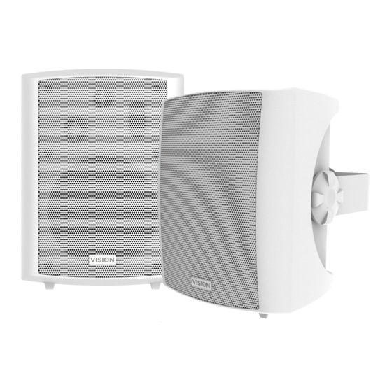
Summary of Contents for Vision SP-1800P
-
Page 1: Owners Manual
SP-1800P ACTIVE LOUDSPEAKERS OWNERS MANUAL www.visionaudiovisual.com/techaudio/sp-1800p SP-1800P_manual_v3_en... -
Page 2: Declaration Of Conformity
WARNING: TO REDUCE THE RISK OF FIRE OR ELECTRIC SHOCK, DO NOT EXPOSE THIS APPLIANCE TO RAIN OR MOISTURE. All products are designed and imported into the EU by „Vision‟ who is wholly owned by „Azlan Logistics Ltd.‟, Registered in England Nr. 04625566 at Lion House, 4 Pioneer Business Park, Clifton Moor, York, YO30 4GH. -
Page 3: Place Of Installation
WARNING SIGNS If you detect an abnormal smell or smoke, turn this product off immediately and unplug the power cord. Contact your reseller or Vision. PACKAGING Save all packing material. It is essential for shipping in the event the unit ever needs repair. - Page 4 CHASSIS Active Loudspeaker Slave Loudspeaker Loudspeaker Cable SP-1800P_manual_v3_en...
-
Page 5: Remote Control
REMOTE CONTROL POWER On / Off VOLUME RESET tone factory reset MUTE TONE treble and bass AUTO STANDBY disable auto-standby – only works for version 2 which has serial control. SP-1800P_manual_v3_en... -
Page 6: Installation
INSTALLATION FIT BRACKETS TO WALL Position brackets over load-bearing studs and use appropriate screws to fix brackets to wall or ceiling. Ensure they are level. NOTE: Do not position the top of bracket closer than 140mm to cornice. INSTALL POWER AND INPUT CABLE Run power and input cables from source positions to the master. - Page 7 CONNECT MASTER LOUDSPEAKER With power switch off, connect input and output cables. VERSION 1: Function Toggle Button Volume / Treble / Bass Function Adjustment buttons -/+ Current Function LED Power LED Minijack Input 2-Phono Input Power Socket (phoenix type) Power Switch Speaker Output (phoenix type) to slave speaker SP-1800P_manual_v3_en...
- Page 8 VERSION 2 FROM EARLY 2017: serial control added, auto standby can be disabled 9-Pin Female Serial input (male to male adaptor included) Minijack Input 2-Phono Input Bass dial Treble dial Volume dial Power Socket (phoenix type) Power Switch Speaker Output (phoenix type) to slave speaker SP-1800P_manual_v3_en...
- Page 9 FIT MASTER LOUDSPEAKER TO BRACKET Fit as shown in point 4. ACTIVATE POWER Turn mains power on with switch on Master. NOTE: Inputs 1 and 2 are both „on‟ all of the time. There is no switching circuit. SP-1800P_manual_v3_en...
- Page 10 RS-232 CODES Function Function Codes Codes 96 11 11 96 AD AD Volume Step 13 96 15 15 96 AE AE Volume Step 14 96 05 05 MUTE 96 AF AF Volume Step 15 96 08 08 TREBLE+ 96 B0 B0 Volume Step 16 96 0D 0D TREBLE-...
-
Page 11: Troubleshooting
TROUBLESHOOTING If your system is not operating properly, please refer to the following information. If the problem persists, disconnect from power and contact your AV reseller immediately. Problem Correction No power light Press volume control. Check power source and power input cable. Check fuse Power light on but no Press volume buttons on master loudspeaker to turn up. -
Page 12: Specifications
SPECIFICATIONS PRODUCT DIMENSIONS: 240 x 178 x 193 mm /9.45″ x 7″ x 7.6″ (length x width x height for each speaker) PRODUCT WEIGHT: 4.78 kg /10.54 lbs (per pair) CONSTRUCTION MATERIAL: ABS COLOUR: White TECHNICAL DETAILS: Amplifier Output: 2 x 30 watts (RMS) Woofer: 5.25″... - Page 13 COMPLIANCE: RoHS, CE/EMC, CE/ EMC-TR, FCC, FCC-V, IEC-TR, RCM, RCM/EMC, RCM/TVC, RCM-D Frequency Response Graph: (dBSPL vs Frequency) SP-1800P_manual_v3_en...
- Page 14 Some Vision products are very technical and require troubleshooting all elements of the installation as it may not be the Vision product at fault. Because of this the manufacturer may refuse to replace the item if an adequate description is not provided.
- Page 15 LEGAL DISCLAIMER: Because we are committed to improving our products, the details above may change without prior warning. This User Manual is published without warranty and any improvements or changes to the User Manual necessitated by typographical errors, inaccuracies of current information, or improvements to programs and/or equipment, may be made at any time and without notice.


Need help?
Do you have a question about the SP-1800P and is the answer not in the manual?
Questions and answers