Table of Contents
Advertisement
Quick Links
Download this manual
See also:
Owner's Manual
Advertisement
Table of Contents

Summary of Contents for Vision SP-5000
- Page 1 SP-5000 OWNERS MANUAL GUIDE DE L’UTILISATEUR MANUAL DE USUARIO GEBRUIKERSHANDLEIDING BEDIENUNGSANLEITUNG MANUALE DEL PROPRIETARIO INSTRUKCJA OBSŁUGI MANUAL DE UTILIZADOR...
- Page 3 Vision is a partner in the TÜV SÜD product certification system. All applicable certification is provided by TÜV. All products are designed and imported into the EU by ‘Vision’ who is wholly owned by Azlan Logistics Ltd, Registered in England Nr. 04625566 at ‘Lion House, Pioneer Business Park, Clifton Moor, York, YO30 4GH’...
-
Page 4: Moving The Unit
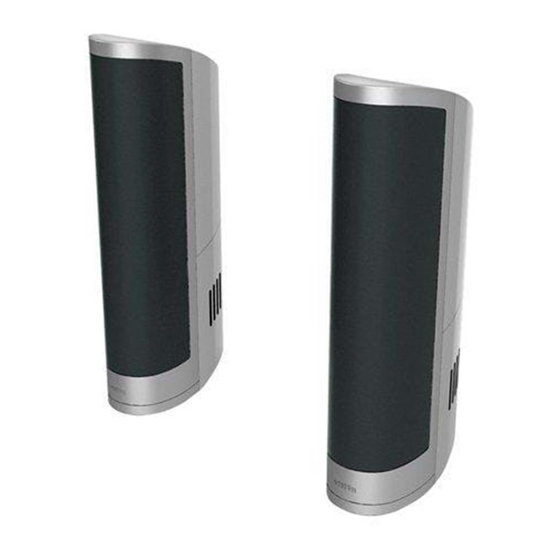
WARNING SIGNS If you detect an abnormal smell or smoke, turn this product off immediately and unplug the power cord. Contact your reseller or Vision. PACkAGING Save all packing material. It is essential for shipping in the event the unit ever needs repair. - Page 5 FRONT 1. Sliding grille 2. Techconnect modules 3. Cable exit cover 4. Speaker Chassis REAR 1. Master speaker 2. M4 × 8 safety cable screw 3. Safety cable 4. Wall brackets 5. Slave speaker...
-
Page 6: Installation Instructions
INSTALLATION INSTRUCTIONS 1. Fix wall brackets Attach wall brackets each side of screen or interactive whiteboard. Ensure they are the same height and level. 2. Remove rear cover from loudspeakers The lower half of the rear panels are held in place by clips. - Page 7 3. Connect cables to the loudspeakers A) NOT USING TECHCONNECT MODULES If using separate connectivity faceplate and amplifier then only speaker cable needs to be connected to the bare-wire terminals shown (1, 2). B) USING TECHCONNECT MODULES If installing with Techconnect modules, then follow these steps: Step 1: Install required Techconnect modules.
- Page 8 4. Using Audio-over-USB decoder To install these loudspeakers so that a PC will recognise it as an audio output device follow these steps: Step 1: Connect USB to the decoder. If using a Techconnect connectivity faceplate USB from the PC will plug into the front of the USB-B module.
-
Page 9: Troubleshooting
5. Replace the rear cover and hang on bracket Re-attach the rear covers, and hang in place. Cable exit covers are included which allow variable sized exit holes. TROUBLESHOOTING If your system is not operating properly, please refer to the following information. If the problem persists, disconnect from power and contact your AV reseller immediately. -
Page 10: Specifications
SPECIFICATIONS ACCESSORIES INCLUDED Product Dimensions (single chassis): • 1 x USB Patch cable 200mm long 520 x 170 x 130mm (h x d x w) • 1 x Power Patch cable • 10 x Techconnect Blank modules Product Weight (pair): tbc kg •...


Need help?
Do you have a question about the SP-5000 and is the answer not in the manual?
Questions and answers