
Related Manuals for SpectraLink K007


Summary of Contents for SpectraLink K007
-
Page 1: Installation Guide
Spectralink Digital DECT Base Station Installation Guide 14219104-IG, Edition 4.0 June 2017, Original document... - Page 2 The drawings and specifications contained herein are the property of Spectralink and shall be neither reproduced in whole or in part without the prior written approval of Spectralink, nor be implied to grant any license to make, use, or sell equipment manufactured in accordance herewith.
-
Page 3: Table Of Contents
Contents About This Guide Related Documentation Description of Base Station Installing the Base Station Frequency Bands Environmental Considerations Power Requirements for the Base Station Base Station Appearence and Components Base Station LED Indicators How to Wall Mount the Base Station Recording the Installation Information Product Compatibility 14219104-IG, Edition 4.0... -
Page 4: About This Guide
This guide explains how to install the Spectralink Digital DECT Base Station. This guide is intended for qualified technicians and the reader is assumed to have a basic knowledge about the Spectralink DECT Server, Spectralink Digital DECT Base Station and Spectralink DECT Repeater. - Page 5 Spectralink Digital DECT Base Station Installation Guide Subject Documentation Spectralink DECT Training material In order to gain access to the Spectralink training mater- ial, you must attend training and become Spectralink Cer- tified Specialist. Please visit http://- partneraccess.spectralink.com/training/classroom-train- for more information and registration.
-
Page 6: Description Of Base Station
The Spectralink Digital DECT Base Station is designed with connector for External Antenna. The Spectralink Digital DECT Base Station is also able to carry out a handover between the RF channels under the same Spectralink Digital DECT Base Station, and handles 4 or 8 DECT speech channels simultaneously. -
Page 7: Installing The Base Station
For best RF coverage, the device must be mounted vertically on walls. Power Requirements for the Base Station The Spectralink Digital DECT Base Station is powered directly via the Spectralink DECT Server 2500/8000 Base Station Interface Card (BIF card). 14219104-IG, Edition 4.0... -
Page 8: Base Station Appearence And Components
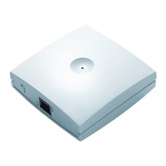
Spectralink Digital DECT Base Station Installation Guide Base Station Appearence and Components Below you will find a description of the base station appearance and components: Digital DECT Base Station - rear Holes for wall mounted screws Connection to server Digital DECT Base Station - front 14219104-IG, Edition 4.0... -
Page 9: Base Station Led Indicators
Spectralink Digital DECT Base Station Installation Guide Digital DECT Base Station - front RJ45 port Base Station LED Indicators Below you will find information about LED indicators on the base station. Front Cover The base station front cover has one indicator describing the base station faults and failures. The indicator is off when the base station is not powered. - Page 10 Spectralink Digital DECT Base Station Installation Guide LED Indicator Meaning Steady red for 5 seconds followed by Reset to factory settings fast red flashing 14219104-IG, Edition 4.0 June 2017, Original document...
-
Page 11: How To Wall Mount The Base Station
The base station must be mounted vertically on the wall for best coverage. 1. Use a twisted pair cable, cat. 5e or higher, between the base station and Spectralink DECT Server with an RJ45 connector at the base station end of the cable. Connect the cable to the plug using the two inner connectors of the plug. -
Page 12: Product Compatibility
If you have any questions about product compatibility, contact your system administrator. You can use the Spectralink Digital DECT Base Station and with other Spectralink products as iden- tified by the type approval model ID and/or part number located on the label of the product. - Page 13 Spectralink Digital DECT Base Station Installation Guide Spectralink Server Spectralink DECT Server 2500 K017 Spectralink DECT Server 8000 K016 Power Supply, 19.0V (only Server 2500) 8476 9905 Power Supply, 19.0V (only Server 8000) 8476 9902 Cable for Power Supply: AU version...
Need help?
Do you have a question about the K007 and is the answer not in the manual?
Questions and answers