Table of Contents
Advertisement
Quick Links
Download this manual
See also:
Installation Manual
Advertisement
Table of Contents

Subscribe to Our Youtube Channel
Related Manuals for MUND CLIMA MUC-W7/SE


Summary of Contents for MUND CLIMA MUC-W7/SE
-
Page 1: Service Manual
Universal FCU DC Service manual MUC-W7 MUC-W7/CE MUC-W7/SE CL04580 to CL04594 English www.mundoclima.com www.mundoclima.com... -
Page 2: Table Of Contents
Contents 1. Features ..............................2 2. External Appearance ..........................2 3. Products Lineup ............................. 3 4. Nomenclature ............................3 5. Specifications ............................4 6. Dimensions ............................... 7 7. Service Spaces ............................9 8. Wiring Diagrams ........................... 10 9. Installation ............................... 11 Transport and handling ........................ -
Page 3: Features
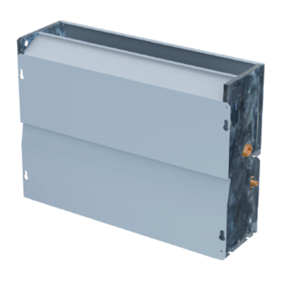
Thanks to the DC Fan Motor, the unit operates in lower power consumption and lower operating sound level. Meet CE certification requirements The unit can meet the latest CE certification requirements for using DC Fan Motor. Movable louver makes wide angle air flow 2. External Appearance MUC-W7/CE MUC-W7/SE General Information... -
Page 4: Products Lineup
3. Products Lineup Air volume Model External static pressure Power supply (CFM) MUC-07-W7 MUC-11-W7 MUC-W7/SE: 12 Pa MUC-16-W7 220~240V-1Ph-50Hz MUC-W7/CE: 0 Pa MUC-19-W7 MUC-24-W7 4. Nomenclature SE: Sin Envolvente CE: Con Envolvente W7: Fan Coil Serie W7 WF: Fan Coil Serie WF HG: Fan Coil Serie HG HP4: Fan Coil Alta Presión Serie 4... -
Page 5: Specifications
(none) (none) MUC-07-W7 Power supply V/Ph/Hz 220-240/1/50 255/215/190 425/360/320 510/430/380 Air flow(H/M/L) 150/125/110 250/210/190 300/250/220 MUC-W7/SE: 12 Pa MUC-W7/CE: 0 Pa External static pressure Capacity (H/M/L) 1.74/1.31/1.05 1.84/1.48/1.18 2.84/2.21/1.63 Cooling Water flow rate Water pressure drop 16.3 Capacity (H/M/L) 2.04/1.42/1.25 2.20/1.66/1.28... - Page 6 MUC-11-W7 MUC-16-W7 Power supply V/Ph/Hz 220-240/1/50 680/580/510 765/650/570 850/720/640 Air flow(H/M/L) 400/340/300 450/380/335 500/420/375 MUC-W7/CE: 0 Pa MUC-W7/SE: 12 Pa External static pressure Capacity (H/M/L) 3.03/2.41/1.72 4.43/3.21/2.52 4.74/3.53/2.55 Cooling Water flow rate Water pressure drop 19.3 30.1 27.7 Capacity (H/M/L) 3.87/2.95/2.09...
- Page 7 Model Power supply V/Ph/Hz 220-240/1/50 1020/870/765 1360/1160/1020 1530/1300/1150 Air flow(H/M/L) 600/510/450 800/680/600 900/760/675 External static pressure MUC-W7/CE: 0 Pa MUC-W7/SE: 12 Pa Capacity (H/M/L) 5.51/3.92/2.99 5.88/4.77/3.61 6.87/5.32/4.31 Cooling Water flow rate 1011 1182 Water pressure drop 16.6 26.5 31.4 Capacity (H/M/L) 7.00/5.11/3.86...
-
Page 8: Dimensions
6. Dimensions Cased type (MUC-W7/CE) Vista trasera Conexiones hidráulicas Dimensions (unit: mm) Model MUC-11-W7/CE MUC-16-W7/CE MUC-19-W7/CE MUC-24-W7/CE MUC-07-W7/CE A(mm) 1000 1200 1500 1500 1284 1284 B(mm) C(mm) 1200 1200 1226 1226 D(mm) General Information... - Page 9 Uncased type (MUC-W7/SE) Vista trasera Conexiones hidráulicas Dimensions (unit: mm) Model MUC-11-W7/SE MUC-07-W7/SE MUC-16-W7/SE MUC-19-W7/SE MUC-24-W7/SE 1250 1250 A(mm) 1226 B(mm) 1226 1200 C(mm) 1200 1232 D(mm) 1232 1386 E(mm) 1086 1386 General Information...
-
Page 10: Service Spaces
7. Service Spaces Cased type ≥a ≥a ≥b a (mm) ≥a ≥a b (mm) Uncased type ≥a ≥b ≥a ≥b a (mm) ≥a ≥a b (mm) General Information... -
Page 11: Wiring Diagrams
8. Wiring Diagrams MUC-07/11/16-W7 MODEL DIAL CODE MUC-07-W7 MUC-11-W7 MUC-16-W7 MUC-19-W7 MUC-24-W7 MUC-19/24-W7 2020804B7618 MODEL DIAL CODE SW1 SW2 LED4 MAIN BOAD ALARM EARTH MUC-07-W7 MUC-11-W7 MOTOR REACTOR MUC-16-W7 HI MID LOW MUC-19-W7 YELLOW/GREEN POWER IN MUC-24-W7 Ground wire Nuetral wire POWER IN Three-speed switch Live wire... -
Page 12: Installation
9. Installation 9.1 Transport and handling Caution: Do not open or tamper with the packaging before installation. The units should only be moved and lifted by specialized personnel trained in these operations. Check on arrival that the unit has not been damaged during transport and that it is complete with all its parts. To remove the packaging, please follow below instructions: Check for visible damage. -
Page 13: Units Installation
Uncased type ≥a ≥b ≥a ≥b a (mm) ≥a ≥a b (mm) 9.4 Units installation Caution: Installation must only be carried out by qualified technicians, trained to work with air-conditioning and refrigeration systems. Incorrect installation could lead to unit malfunctioning and a consequent deterioration in performance. - Page 14 Parts instruction: 1. Pipe connections; 2. Fixing slots; 3. Defrosting tray; 4. Condensate discharge; 5. Air filter; 6. Fans; 7. Heat exchanger; Mark out the fixing points on the wall or ceiling either by marking through the drillings in the unit or by referring to the measurements given in “7 DIMENSIONS”.
- Page 15 Setting up the condensate drainage system The condensation drainage system must be set up with an adequate fall to ensure that the water escapes properly. Following are directions for setting up a proper condensation drainage system. connect to the unit condensate discharge or defrosting tray.
-
Page 16: Electrical Connections
9.5 Electrical connections Caution: Electrical connection of the unit must be carried out by qualified personnel in compliance with the regulations in effect in the country where the unit is installed. The company shall not be held liable for damage to persons or property caused by incorrect electrical connection. -
Page 17: Maintenance
pipeline water and vacuum air from the system until there have water flow out from bolt holes, and then tighten the bolts of the system. Shutdown the system that showed at the figure by slotted screwed and replaces the side cover panel. Preliminary checks before startup ... - Page 18 Release the air in the water system. Remove the casing of the machine (for casing type); Start the system and run for a few minutes; Stop the system; Loosen the release screw on the inlet manifold and release the air. Repeat the operation several times until no more air comes out of the system.
- Page 19 ASK FOR MORE INFORMATION Phone: (+34) 93 446 27 81 eMail: info@mundoclima.com TECHNICAL ASSISTANCE Phone: (+34) 93 652 53 57 www.mundoclima.com...
Need help?
Do you have a question about the MUC-W7/SE and is the answer not in the manual?
Questions and answers