
Related Manuals for MUND CLIMA MUCS-24 C


Summary of Contents for MUND CLIMA MUCS-24 C
- Page 1 MUND CLIMA ® SPLIT CASSETTE COOL ONLY: MUCS-24 C MUCS-41 C HEAT PUMP: MUCS-24 H MUCS-41 H User's manual...
-
Page 2: Table Of Contents
CONTENT Operation mechanism and working range Names and functions of parts Safety cautions Remote control operation procedure Optimum operation Trouble shooting Installation notes Care and maintenance Technical specifications Installation accessories and drawings Indoor unit installation Outdoor unit installation Test and check items after installation Thank you purchasing this MUNDOCLIMA air conditioner.Read this MANUAL carefully prior to use of the air conditioner and then keep it properly for future reference. -
Page 3: Operation Mechanism And Working Range
Operation mechanism and working range. Working temperature range. Indoor side DB/WB ( ) Outdoor side DB/WB ( ) maximum cooling 32/23 43/26 minimum cooling 21/15 21/15 maximum heating 27/- 24/18 minimum heating 20/- -5/-6 Schematic diagram for cooling only type. 1. -
Page 4: Names And Functions Of Parts
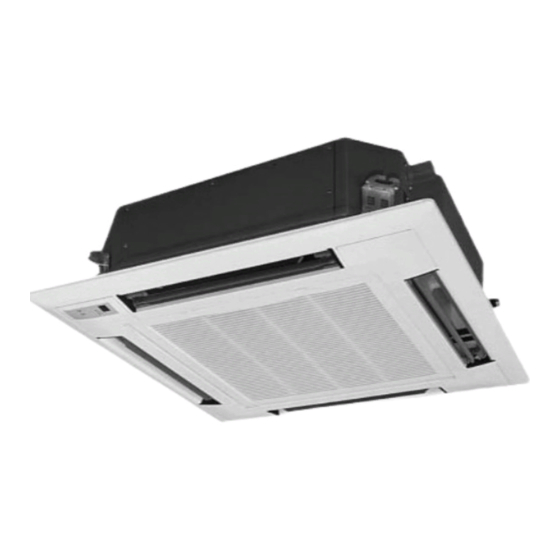
Air flow flap (at air outlet) Refrigerant piping connection electric wire Air outlet Remote controller The built-in air filter (page 6~14) removes dust and dirt Air intake grille MUCS-24 C Outdoor unit MUCS-24 H Refrigerant pipe Air outlet Air intake... - Page 5 Names and functions of parts. Indoor unit Drainage device (built-in) Drains water removed from the indoor unit dur- ing cooling Drainage pipe Air flow flap (at air outlet) Refrigerant piping connection electric wire Air outlet Remote controller The built-in air filter (page 6~14) removes dust and dirt Air intake grille...
-
Page 6: Safety Cautions
Safety cautions Read the following carefully to assure safe use. Warning Avoid direct air flow to your body and avoid Check whether the installed stand is still firm excessive heating or cooling,which may make enough after the unit has operated for a long you feel uncomfortable and do harm to your time. - Page 7 Safety cautions Warning Do not check or repair during the unit is Do not use other operating. It is very dangerous. heating equip- ment near the air conditioner. It will affect the cooling perfor- mance. Never place objects near the air intake and the air outlet of the unit. It may affect performance or stop operation of the unit.
-
Page 8: Remote Control Operation Procedure
Remote control operation procedure Name and Function-Remote control Note: Be sure that there are no obstructions. The remote control signal can be received at a distance of up to about 10m. Don’t drop or throw the remote control. Don’t place the remote control in a location exposed to direct sunlight. SWING button When it is pressed, the louvers... - Page 9 Remote control operation procedure Name and Function-Remote control. (Remove the cover) Note: This type of remote controller is a kind of new current controller.some buttons of the controller which are not available to this Air conditioner will not be described below.
- Page 10 Remote control operation procedure COOL mode operation procedure According to difference between room temp. and set temp., microcomputer can control cooling = = = = = on or not. If room temp. is higher than set temp., compressor runs at COOL mode. If room temp.
- Page 11 Remote control operation procedure HEAT mode operation procedure If room temp. is lower than set temp., compressor runs at HEAT mode; If room temp. is higher than set temp., compressor and outdoor fan mortor stop, only indoor = = = = = fan mortor runs.
- Page 12 Remote control operation procedure DRY mode operation procedure If room temp. is lower than set temp., compressor ,outdoor and indoor fan mortor stop. If room = = = = = temp. is between= = = = = 2 of set temp., Air conditioner is drying.If room temp. is higher than set temp., it’s at COOL mode.
- Page 13 Remote control operation procedure AUTO mode operation procedure At AUTO mode operation, standard TEMP. is 25 for COOL mode and 20 for HEAT = = = = = mode. SWING AUTO FAN OPER AUTO SWING SLEEP LIGHT HUMID TIMER ON TIMER OFF ANION SAVE MODE 1 / 0...
- Page 14 Remote control operation procedure TIMER operation procedure SWING AUTO FAN SWING TIMER ON OFF SLEEP At stopping,press TIME LIGHT HUMID ON button, set ON TIME in range of 0 to 24 hour to TIMER ON TIMER OFF ANION SAVE start the unit automatically. MODE 1 / 0 At operating,press TIMER...
- Page 15 Remote control operation procedure SLEEP mode operation procedure When the unit is cooling or drying, if SLEEP operation is set, TEMP. would increase 1 in 1 hour and 2 in 2 hour. Indoor fan motor runs at low speed. When the unit is heating , if SLEEP operation is set, TEMP. would decrease 1 in 1 hour and in 2 hours.
- Page 16 Remote control operation procedure How to insert batteries 1. Remove the cover from the back of the remote control. 2. Insert the two batteries ( Two AAA dry - cell batteries ) and press but- ton “ACL”. 3. Re - attach the cover. Note: Don’t confuse the new and worn or different batteries.
-
Page 17: Optimum Operation
Optimum operation Adjust the room temperature properly Adjust the room temperature properly for a comfortable environment. Never place anything under the indoor unit that is to be kept dry. Water may drop from the indoor unit when the humidity is over 80% or when the drainage outlet is clogged. Turn off the main power supply swittch when it is not to be used for long periods of time When the main power switch is truned on,some watts of electricity is being used even if the system is not operating. -
Page 18: Trouble Shooting
Trouble shooting Warning * In case of something abnormal (such as bad smell), shut off the power switch immediately and contact service center. * Do not repare the air conditioner by yourself because wrong repair may cause fire,please contact service center to do it for you. - Page 19 Trouble shooting The following are not troubles “ Trouble” Cause Restart right after stopping Once the unit is stopped, it will not operate The unit does not Press SET TEMP.and then release immediately. for about 3 minutes to protect it operate when Power is switched on Wati for 1 minute...
-
Page 20: Installation Notes
Be sure to install enough ampere rating air power switch. (specifications are illustrated in the following table) Do not connect the earth wire to gas or water pipes,lightning condutor or telephone earth wire. Model Air power switch MUCS-24 C/H MUCS-24 C/H MUCS-41 C/H Water pipe... -
Page 21: Care And Maintenance
Care and maintenance Please pull out the power plug after you used the air conditioner. Warning Pull out the power plug before cleaning Do not splash water directly to the unit How to clean the air filter Screws 1.Open the suction grille Use screwdriver screws the two screws. - Page 22 Care and maintenance 4.Fix the air filters Fix three air cleaner on the air filter and then fix the air filter to the suction grille by hanging it to the projected portion above suction grille. Set air filter by sliding the knob on the back of the saction grille inward.
- Page 23 Care and maintenance Changing air cleaner 1.Open the suction grille See step 1 of “ How to clean the air filter” 2.Remove the air cleaner Remove the air filter,and remove the air cleaner affter unscrewing. 3.Take off packing bag and put in new static electricity fiber filer,then fix them on the air filter.
- Page 24 Care and maintenance How to clean the air outlet and case. Clean with soft cloth or use water and neutral detergent. Do not use gasoline,benzene,thiner,polishing powder,liquid insecticide,which may cause discoloring or warping.If the air flow flap is very dirty,you may remove it to clean as shown below. Detach and fix the flap Detach and fix the flap 1.Detach the flap...
-
Page 25: Technical Specifications
Technical specifications... -
Page 26: Installation Accessories And Drawings
Sealing bar PVC tape Remote controller 1.5V Battery Plastic sleeve MUCS-24 H H07RN-F 5 MUCS-41 C Signal control wire MUCS-24 C MUCS-41 C H07RN-F 4 MUCS-41 H H07RN-F 4 MUCS-41 H MUCS-24 C H05RN-F 3 0.75 MUCS-24 H Signal control wire... - Page 27 Installation accessories and drawings Installation drawings Indoor unit 20mm or more Air intake 1500mm 1500mm or more or more unit: mm Model MUCS-24C/MUCS-24H Ground (Fig.1) MUCS-41C/MUCS-41H Outdoor unit 500mm or more 500mm 1000mm 1000mm or more or more or more 300mm or more 2000mm 2000mm...
-
Page 28: Indoor Unit Installation
Indoor unit installation Location 1.Do not place object near the air oulet so that conditioned air can reach the whole room. 2.Be sure to install the indoor unit firmly and horizontly. 3.Select the place that can support 4 times of the indoor unit’s weight and will not increase noise and vibration. 4.Select a place easy to drain water and connect with the outdoor unit. - Page 29 Indoor unit installation Indoor unit installation 1.Install the indoor unit temporarily. Attach the hanger bracket to the suspension bolt.Be sure to fix it securely by using a nut and washer from the upper and lower sides of the hanger bracket.the washer fixing plate =will prevent the washer from falling.
- Page 30 Indoor unit installation Connection of refrigerant pipe Besure to use both a spanner and torque wrench together as shown in the drawing,connecting or disconnecting pipes to/from the unit. Refer to table 1 to determine the proper tightening torque (over tightening may damage the flare and cause leaks.) When conecting the flare nut,coat the flare both inside and outside with refrigerating machine oil and initially tighten by hand 3 or 4 turns.
- Page 31 Indoor unit installation Drainage pipe 1.Installation of drainage pipe. The diameter of the drainage pipe should be greater than of equal to the diameter of the connecting pipe[vinyl tube, pipe size:25mm(outer dimension)] Keep the drainage pipe short and sloping downwards at a gradient of at least 1/100 to prevent air pockets from forming.
- Page 32 Indoor unit installation 2.After finishing installation,check if drainage water flows smoothly. Add approximately 600 cc of water to the drainage trough through air outlet or inspection hole slowly and check drainage flow. When electric wiring is finished,check drainage flow during cooling operation. Method of adding water.
- Page 33 Indoor unit installation three phase one phase Come from outside unit Power supply terminal board Clamp (3 for cool/heat 5 for cool only) Clamp Rubber bush Control box lid (2) Seal here to avoid leakage Rubber bush Control box lid (1) Precautions:Be sure to connect the indoor unit and outdoor unit at right poles.
- Page 34 Indoor unit installation Hook Latch Piping position Swing flap motor Sealing material Indoor unit Ceiling Air outlet Panel (Fig.4) Precautions 1.Improper screwing of the screws may cause the troubles shown in Fig.5 Air leak Air leak from ceiling Contamination dew condensation,dew dripping (Fig.5)
- Page 35 Indoor unit installation 2. If gap is still left between the celling and the panel after screwing the screws,readjust height of the indoor unit body (Refer to Fig.6) Adjustment of the indoor unit body from the holes in the corner of the panel is possible if the indoor unit is kept leveled and the drainage pipe piping etc is unaffectecd.
-
Page 36: Outdoor Unit Installation
Outdoor unit installation Selecting installation site Select an installation site where the folliwing conditions are satisfied and that meets with your customer’s approval. Places which are well-ventilated. Safe places which can withstand the unit’s weight and vibration and where the unit can be installed level. Places where the unit does not bother next-door neighbors. - Page 37 Outdoor unit installation Electric wiring (1) Read the name plate carefully,then arrange wiring according to the “ WIRING DIAGRAM ”. (2) A circuit breaker capable of shutting down power supply to the entire system must be installed. (3) Earth properly. (4) All wiring must be perfomed by a skilled electrican according to the “...
-
Page 38: Test And Check Items After Installation
Test and check item after installation Test operation 1. Prepare for test (1) Do not turn on the power switch before all installation is finsihed. (2) Connect wires corectly and firmly. (3) Open the check valve. (4) Remove all dust. 2.
Need help?
Do you have a question about the MUCS-24 C and is the answer not in the manual?
Questions and answers