
Related Manuals for MUND CLIMA MUCSR-H3


Summary of Contents for MUND CLIMA MUCSR-H3
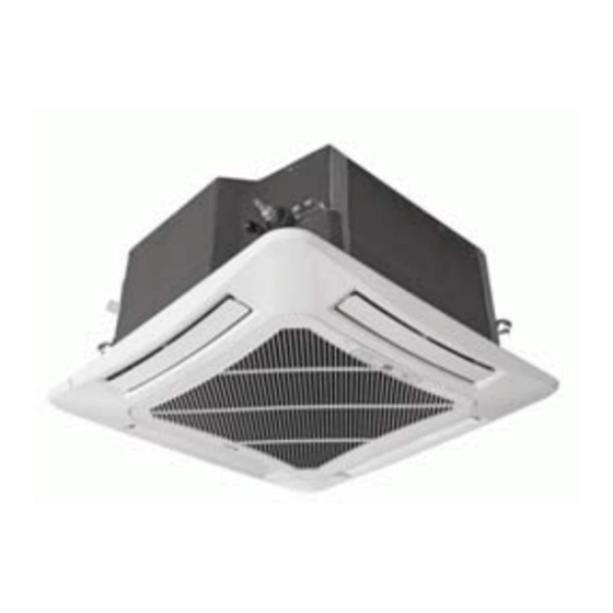
- Page 1 CASSETTE SERIE H3 Installation and user's manual MUCSR-H3 CL20842 to CL20849 www.mundoclima.com English...
- Page 2 Cassette Serie H3 - Super DC Inverter CONTENTS Installation manual ..................3 User' ' ' s manual .....................36...
-
Page 3: Table Of Contents
Cassette Serie H3 - Super DC Inverter Installation manual 1. Safety Precautions ......................... 4 2. Outline of the Unit and Main Parts ..................3. Preparative for Installation ....................3.1. Standard Accessory Parts .................... 7 3.2. Selection of the Installation Location ................3.3. -
Page 4: Safety Precautions
Cassette Serie H3 - Super DC Inverter 1. Safety Precautions This mark indicates procedures which, if improperly performed, might lead to the WARNING! death or serious injury of the user. This mark indicates procedures which, if improperly performed, might possibly result CAUTION! in personal harm to the user, or damage to property. - Page 5 Cassette Serie H3 - Super DC Inverter (14). During installation, attach the refrigerant piping securely before running the compressor. If the compressor is not attached and the stop valve is open during pump-down, air will be sucked in when the compressor is run, causing abnormal pressure in the freezer cycle which will lead to breakage and even injury.
-
Page 6: Outline Of The Unit And Main Parts
Cassette Serie H3 - Super DC Inverter 2. Outline of the Unit and Main Parts Indoor 1. Drainage device 2. Drainage pipe 3. Air flow flap Outdoor 4. Connection pipe Air inlet 5. Wireless Controller 6. Wired Controller 7. Big handle 8. -
Page 7: Preparative For Installation
Cassette Serie H3 - Super DC Inverter 3. Preparative for Installation 3.1 Standard Accessory Parts The standard accessory parts listed below are furnished and should be used as required. Table 1 Indoor Unit Accessories Name Appearance Q'ty Usage To connect with the hard PVC drain Drain Hose pipe To fix the hook on the cabinet of the... -
Page 8: Selection Of The Installation Location
Cassette Serie H3 - Super DC Inverter 3.2 Selection of the Installation Location WARNING! The unit must be installed where strong enough to withstand the weight of the unit and fixed securely, otherwise the unit would topple or fall off. CAUTION! ①... - Page 9 Cassette Serie H3 - Super DC Inverter Table 3 MUCSR-12 MUCSR-18 MUCSR-24 MUCSR-30 MUCSR-36 MUCSR-42 MUCSR-48 MUCSR-60 WARNING! ① . Install the unit where it will not be tilted by more than 5°. ② . During installation, if the outdoor unit has to be exposed to strong wind, it must be fixed securely. If possible, do not install the unit where it will be exposed to direct sunlight.
-
Page 10: Connection Pipe Requirement
Cassette Serie H3 - Super DC Inverter 3.3 Connection Pipe Requirement CAUTION! The maximum length of the connection pipe is listed in the table below. Do not place the units between which the distance exceeds the maximum length of the connection pipe. Table 4 Size of Fitting Max. - Page 11 Cassette Serie H3 - Super DC Inverter Table 6 Minimum Sectional Area of Power Capability of Air Model Power Cable and Earth line Supply Switch(A) MUCSR-12 MUCSR-18 MUCSR-24 MUCSR-30 220-240V~ 50Hz MUCSR-36 MUCSR-42 MUCSR-48 MUCSR-60 380-415V 3N~ 50Hz Notes: ① . The fuse is located on the main board.
-
Page 12: Installation Of The Unit
Cassette Serie H3 - Super DC Inverter 4. Installation of the Unit 4.1 Installation of the Indoor Unit 4.1.1 Indoor unit dimension Table 7 MUCSR-12 MUCSR-18 MUCSR-24 MUCSR-30 MUCSR-36 MUCSR-42 MUCSR-48 MUCSR-60 4.1.2 Installing the Main Body Unit Fig.5... -
Page 13: Installation Of The Outdoor Unit
Cassette Serie H3 - Super DC Inverter (1). Install the hoisting stand on the hoisting screw by using nuts and gaskets at both the upper and lower sides of the hoisting stand. To prevent the gasket from breaking off, a gasket anchor board can be helpful. - Page 14 Cassette Serie H3 - Super DC Inverter 4.2.1 Outdoor unit dimension Table 8 Unit: mm Item Model MUCSR-12 MUCSR-18 MUCSR-24 MUCSR-30 MUCSR-36 MUCSR-42 MUCSR-48 MUCSR-60 4.2.2 Condensate Drainage of the Outdoor Unit(Only for the heat pump unit) (Fig.11) (1). It is required to install a drain pipe for the outdoor unit to drain out the condensate water during heating operation.
-
Page 15: Installation Of The Connection Pipe
Cassette Serie H3 - Super DC Inverter 4.3 Installation of the Connection Pipe 4.3.1 Flare Processing (1). Cut the connection pipe with the pipe cutter and remove the burrs. (2). Hold the pipe downward to prevent cuttings from entering the pipe. (3). - Page 16 Cassette Serie H3 - Super DC Inverter CAUTION! ① . To prevent breaking of the pipe, avoid sharp bends. Bend the pipe with a radius of curvature of 150 mm or over. ② . If the pipe is bent repeatedly at the same place, it will break. 4.3.3 Connecting the Pipe at the Indoor Unit Side Detach the caps and plugs from the pipes.
- Page 17 Cassette Serie H3 - Super DC Inverter Table 9 Flare nut tightening torque Pipe Diameter Tightening Torque 1/4˝(Inch) 15-30 (N·m) 3/8˝(Inch) 35-40 (N·m) 5/8˝(Inch) 60-65 (N·m) 1/2˝(Inch) 45-50 (N·m) 3/4˝(Inch) 70-75 (N·m) 7/8˝(Inch) 80-85 (N·m) CAUTION! Be sure to connect the gas pipe after connecting the liquid pipe completely. 4.3.4 Connecting the Pipe at the Outdoor Side Unit Tighten the flare nut of the connection pipe at the outdoor unit valve connector.
-
Page 18: Vacuum And Gas Leakage Inspection
Cassette Serie H3 - Super DC Inverter 4.3.7 Liquid Pipe and Drain Pipe Sealed If the outdoor unit is installed lower than the indoor unit (See Fig.18) Saddle (1). A drain pipe should be above ground and the end of the pipe does not dip into water. - Page 19 Cassette Serie H3 - Super DC Inverter (5). The evacuation duration depends on the unit’s capacity, generally, 15 minutes for the 12K units, 20 minutes for the 18K units, 30 minutes for the 24/30/36K units, 45 minutes for the 42/48/60 units. And verify if the pressure gauge at the low pressure side of the manifold valve assembly reads -1.0Mp (-75cmHg), if not, it indicates there is leak somewhere.
-
Page 20: Installation Of The Drain Hose
Cassette Serie H3 - Super DC Inverter Outdoor Oil bend Indoor Oil bend Fig.21 4.5 Installation of the Drain Hose 4.5.1 Installationof Drain Piping (1). Keep piping as short as possible and slope it downwards at a gradient of at least 1/100 so that air may not remain trapped inside the pipe. - Page 21 Cassette Serie H3 - Super DC Inverter (3). When unifying multiple drain pipes, install the pipes as Fig.23. Select converging drain pipes whose gauge is suitable for the operating capacity of the unit.(take the cassette type unit for example) T-joint converging drain pipes T-joint converging drain pipes Fig.23 (4).
- Page 22 Cassette Serie H3 - Super DC Inverter 3-way connection of drainage pipe joint Connection of drain elbow Connection of horizontal pipe Fig.27 Fig.28 Fig.29 4.5.3 Precautions When Doing Riser Piping Work (1). Make sure that heat insulation work is executed on the following 2 spots to prevent any possible water leakage due to dew condensation.
-
Page 23: The Panel Installation
Cassette Serie H3 - Super DC Inverter Drain hose(attachment) Fig.32 4.5.4 Testing of Drain Piping After piping work is finished, check if drainage flows smoothly. Shown in the Fig.33, Add approximately 1liter of water slowly into the drain pan and check drainage flow during COOL running. - Page 24 Cassette Serie H3 - Super DC Inverter (2). Improper screwing of the screws may cause the troubles shown in Fig.35. Condensate Fig.35 (3). If gap still exists between ceiling and decoration panel after tightening the screws, readjust the height of the indoor unit. (Fig.36) Fig.36 (4).
-
Page 25: Electrical Wiring
Cassette Serie H3 - Super DC Inverter (4). Adjust the panel along the direction indicated by the arrow as shown in Fig.38. (5). Tighten the screws until the thickness of the sealing material between the panel and the indoor unit reduces to 5-8cm. Fig.38 4.7. - Page 26 Cassette Serie H3 - Super DC Inverter ⑤ . Use a special branch circuit breaker and receptacle matched to the capacity of the air conditioner. ⑥ . The special branch circuit breaker is installed in the permanent wiring. Always use a circuit that can trip all the poles of the wiring and has an isolation distance of at least 3mm between the contacts of each pole.
- Page 27 Cassette Serie H3 - Super DC Inverter Fig.40 Fig.41 (3). How to fix connection cord and power cord by cord clamp After passing the connection cord and power cord through the insulation tube, fasten it with the cord clamp.(Fig.41) WARNING! ①...
- Page 28 Cassette Serie H3 - Super DC Inverter MUCSR-36 MUCSR-42 Power cord 3×2.5mm (H07RN-F) Power cord 3×1.0mm (H05RN-F) Communication Cords 2×0.75mm (H05RN-F) MUCSR-48 Power cord 3×6.0mm (H07RN-F) Power cord 3×1.0mm (H05RN-F) Communication Cords 2×0.75mm (H05RN-F) MUCSR-60 Power cord 3×2.5mm (H07RN-F) Power cord 3×1.0mm (H05RN-F) Communication Cords 2×0.75mm (H05RN-F)
- Page 29 Cassette Serie H3 - Super DC Inverter CAUTION! ① . The power cord and the wire of the fresh air valve are high-voltage, while the communication cord and connection wire of the wired controller are low-voltage. They should run separately against electromagnetic interference.
-
Page 30: Installation Of Controllers
Cassette Serie H3 - Super DC Inverter Three-phase: 5. Installation of Controllers Refer to the Installation Manual of the controller for more details. 6. Test Running 6.1 Trial Operation and Testing (1). The meaning of error codes as shown below: Table 11 Number Error code... - Page 31 Cassette Serie H3 - Super DC Inverter IPM protection DC fan motor error Drive desynchronizing protection Pfc protection Activation failure Compressor phase sequence protection Compressor stalling protection Power protection Indoor and outdoor mismatch 4-way valve direction changing protection Drive reset protection Over-current protection Communication error between main control and drive Drive module sensor error...
-
Page 32: Working Temperature Range
Cassette Serie H3 - Super DC Inverter ◆ “88” Display: When there is no error, and it receives valid remote control information. It will display the temp setup for 5s, then display the temp of indoor. When the unit has error, It will display the error code. When there are more than one error, the error code will be displayed alternately. -
Page 33: Troubleshooting And Maintenance
Cassette Serie H3 - Super DC Inverter 7. Troubleshooting and Maintenance 7.1 Troubleshooting If your air-conditioning unit suffers from abnormal operation or failure, please first check the following points before repair: Table 13 Failure Possible Reasons ① . The power supply is not connected. ②... -
Page 34: Routine Maintenance
Cassette Serie H3 - Super DC Inverter 7.2 Routine Maintenance Only a qualified service person is allowed to perform maintenance. Before accessing to terminal devices, all power supply circuits must be disconnected. Do not use water or air of 50°C or higher for cleaning air filters and outside panels. Notes: Do not operate the air conditioner with the filter uninstalled, otherwise dust would come into ①... - Page 35 Cassette Serie H3 - Super DC Inverter 2. Disassemble the air inlet grille Open the air inlet grille at 45°, raise it and remove the grille. 3. Disassemble the filter screen Draw out the filter screen and remove it. Filter screen 4.
-
Page 36: Users Manual
Cassette Serie H3 - Super DC Inverter Users manual 1. Wireless remote controler Y B1FA ..................1.1. User notice ........................1.2. Control panel of the w i reless remote controller ............1.3. Introduction for special function ................. 1.4. Replacement of batteries .................... 2. - Page 37 Cassette Serie H3 - Super DC Inverter 2.3.14. SAVE Function Setting ..................58 2.3.15. E-HEATER Setting ....................2.3.16. Blow Function Setting ..................2.3.17. Filter Setting ......................2.3.18. Quiet Function Setting ..................2.3.19. Ultra-Dry Setting ....................2.3.20. Other Functions ....................2.4. Installation of the Wired Controller ................66 2.4.1 Standard Parts ......................
-
Page 38: Wireless Remote Controler Y B1Fa
Cassette Serie H3 - Super DC Inverter 1. Wireless remote controler YB1F 1.1 User notice CAUTION ! ① Make sure there is no obstruction between the wireless remote controller and the signal receiver. ② The signal receiving distance of the wireless remote controller can be up to 10 metres. ③... - Page 39 Cassette Serie H3 - Super DC Inverter Name Function Description Signal ● Signal transmitter transmitter ● Press this button, and the unit will be turned on; press it once more, and the ON/OFF unit will be turned off. When turning off the unit, the Sleep function will be button canceled, but the presetting time is still remained.
-
Page 40: Introduction For Special Function
Cassette Serie H3 - Super DC Inverter ● Press this button to set up the swing angle, which circularly changes as below: ● When the guide louver starts to swing up and down, if SWING funtions is canceled, the air guide louver will stop and remains at the current position. - Page 41 Cassette Serie H3 - Super DC Inverter ● By pressing this button it is allowed to select displaying the indoor setting temperature or the indoor ambient temperature. ● Indoor setting temperature is default after the indoor unit is energized initially. ●...
-
Page 42: Replacement Of Batteries
Cassette Serie H3 - Super DC Inverter heating quickly so that the ambient temperature will approach the preset temperature as soon as possible. ● About lock Press + and - buttons simultaneously to lock or unlock the keyboard. If the wireless remote controller is locked, the icon will be displayed on it, in which case, any press will get no response but with the mark blinking for three times. -
Page 43: Wired Remote Controler Xk60
Cassette Serie H3 - Super DC Inverter 2. Wired remote controler XK60 2.1 Introduction to the Wired Controller Fig.1 Apariencia del termostato 2.1.1 Appearance and LCD Icons Fig.2 Appearance of the LCD... -
Page 44: Introduction To The Lcd Icons
Cassette Serie H3 - Super DC Inverter 2.1.2 Introduction to the LCD Icons Table 1 Icons Introduction Left and right swing function Up and down swing function Air exchange function Sleep function Auto mode COOL mode DRY mode FAN mode HEAT mode Health function I-Demand function... - Page 45 Cassette Serie H3 - Super DC Inverter Electric heater Blow function Defrosting function Filter cleaning Timer Setting Keycard control / Detected status sensed by human body Quiet function Lock function...
-
Page 46: Press Buttons
Cassette Serie H3 - Super DC Inverter 2.2 Press Buttons 2.2.1 Buttons Fig.3 Press Buttons 2.2.2 Instruction to the Function of Press Buttons Table 2 Press Buttons Function Introduction ①. Function selection and canceling; Enter/Cancel ②. Press it for 5s to enquiry the outdoor and indoor ambient temperature. ①. -
Page 47: Operation Instructions
Cassette Serie H3 - Super DC Inverter 2.3 Operation instructions 2.3.1 On/of f Press the On/Off button to turn on or off the unit. Notes: ①. The state shown in Fig.4 indicates the OFF state of the unit after energization. The state shown in Fig.5 indicates the ON state of the unit after energization. -
Page 48: Temperature Setting
Cassette Serie H3 - Super DC Inverter 2.3.3 Temperature Setting Press ▲ or ▼button to increase or decrease setting temperature under on-state of the unit. If press either of them continuously, temperature will be increased or decreased by 1°C every 0.5s. In Cooling, Dry, Fan and Heating mode, temperature setting range is 16°C~30°C. -
Page 49: Right And Left Swing
Cassette Serie H3 - Super DC Inverter 2.3.5 Right and Left Swing Under the ON state of unit, press the Function button to select the “Right and Left Swing” function option and then press the Enter/Cancel button to activate it. When the Swing function is activated, press the Function button to select the "Right and Left Swing"... -
Page 50: Up And Down Swing
Cassette Serie H3 - Super DC Inverter 2.3.6 Up and Down Swing Under the ON state of unit, press the Function button to select the "Up and Down Swing" function option and then press the Enter/Cancel to activate it. When the Swing function is activated, press the Function button to select the "Up and Down Swing"... -
Page 51: Air Exchange Setting
Cassette Serie H3 - Super DC Inverter Cancellation of Timer Setting: The timer setting can be canceled by press “Timer”. Then , xx. Hour won’t be displayed. Timer Setting under the ON state of the Unit is as shown in Fig.11: Unit On, no timer function Press “Timer”... - Page 52 Cassette Serie H3 - Super DC Inverter 1. The unit continuously runs for 60min, and fresh air valve runs for 6 min. 2. The unit continuously runs for 60min, and fresh air valve runs for 12 min. 3. The unit continuously runs for 60min, and fresh air valve runs for 18 min. 4.
-
Page 53: Sleep Setting
Cassette Serie H3 - Super DC Inverter 2.3.9 Sleep Setting Sleep on: Press the Function button under the ON state of the unit to select the “Sleep” function option and then press the Enter/Cancel button to activate it. Sleep off: When the Sleep function is activated, press the Function button to select the Sleep function option and then press the Enter/Cancel button to deactivate this function. - Page 54 Cassette Serie H3 - Super DC Inverter e.g. If the setting temperature is 25°C, the temperature will rise by 1°C in each hour until it reaches 27°C. 7 hours later, the temperature will drop to 26°C. After that, the unit will run at this temperature.
-
Page 55: Health Setting
Cassette Serie H3 - Super DC Inverter 2.3.10 Health Setting Under unit on status, press “Function” button to select health function with “Health” icon flashing. Press “Enter/Cancel” button to activate health function. When health is on, press “Function” button to set function, with “health” icon flashing. Then press the “Enter/Cancel”... -
Page 56: Vacation Setting
Cassette Serie H3 - Super DC Inverter Unit On, no I-Demand function Press “Function” button to set Press “Enter/Cancel” button to I-Demand function activate I-Demand function Press “Enter/Cancel” button to Press “Function” button to set cancel I-Demand function I-Demand function Fig.17 I-Demand Setting Note: The I-Demand function can be cancelled by mode switch and unit ON/OFF. -
Page 57: Turbo Function Setting
Cassette Serie H3 - Super DC Inverter Unit On, no Vacation function Press “Function” button to set Press “Enter/Cancel” button to vacation function activate vacation function Press “Enter/Cancel” button to Press “Function” button to set cancel vacation function vacation function Fig.18 Vacation Setting Note: ①. -
Page 58: Save Function Setting
Cassette Serie H3 - Super DC Inverter button to select the "Turbo" option and then pressing the Enter/Cancel button. Turbo function setting is as shown in Fig.19: Unit On, no Turbo function Press “Function” button to set Press “Enter/Cancel” button to turbo function activate turbo function Press “Enter/Cancel”... - Page 59 Cassette Serie H3 - Super DC Inverter Cancel button to activate this function. The activated SAVE function can be deactivated by firstly pressing the “Function” button to select the “SAVE” option and then pressing the “Enter/Cancel” button. The energy saving setting is as shown in the Fig.20: Unit On, no Save function Press “Function”...
-
Page 60: E-Heater Setting
Cassette Serie H3 - Super DC Inverter 2.3.15 E-HEATER Setting E-HEATER: in the HEAT mode, “E-HEATER” function is allowed to be activated to improve the heating efficiency. Generally, it will be activated automatically as the unit goes into the HEAT mode through any button operations . -
Page 61: Filter Setting
Cassette Serie H3 - Super DC Inverter Deactivation of the “Blow” Function: The activated “Blow” function can be deactivated by firstly pressing the Function button to select the “Blow” option and then pressing the Enter/Cancel button. BLOW function setting is as shown in Fig.22: Unit On, no Blow function Press “Function”... - Page 62 Cassette Serie H3 - Super DC Inverter Unit On, no Filter function Press “Function” button to set filter function the pollution level Press “Function” button to set Press “Enter/Cancel” button “00” shown at the timer area filter function to activate filter function Press “Enter/Cancel”...
-
Page 63: Quiet Function Setting
Cassette Serie H3 - Super DC Inverter “0” shows up at the second place, the accumulated operating hour reaches 1400h. Every increase of the number means another 400h is accumulated. When “9” shows up, it means the operating hour reaches 5000h. ④. -
Page 64: Ultra-Dry Setting
Cassette Serie H3 - Super DC Inverter Unit On, no Quiet function Press “Function” button to set Press “Enter/Cancel” button to quiet function activate quiet function Press “Enter/Cancel” button to Press “Function” button to set cancel quiet function quiet function Fig.24 Quiet function setting Notes: ①. - Page 65 Cassette Serie H3 - Super DC Inverter 2.3.20.2 Memory Function Memory switchover: Under the OFF state of the unit, press the Mode and ▲ buttons at the same time for 5s to switch memory modes. When setting the memory mode, “MEMORY” will be displayed.
-
Page 66: Installation Of The Wired Controller
Cassette Serie H3 - Super DC Inverter Unit off Simultaneously press “Function” Press “Mode” button to set till and “Timer” button for 5s, the “05” is shown on the temperature wired controller will enter displayed area. Then the unit will parameter setting interface. -
Page 67: Installation Location And Installation Requirements
Cassette Serie H3 - Super DC Inverter 2.4.2 Installation Location and Installation Requirements (1). Do not install the wired controller in the damp place or under direct sunlight. (2). Do not install the wired controller close to the hi-temperature object or place where the wired controller is likely to suffer water spray. -
Page 68: How To Remove The Wired Controller
Cassette Serie H3 - Super DC Inverter Brief instructions: ①. Pull out the 2-core signal line from the mounting hole and pass this line through the round hole located at the bottom of the wired controller. ②. Use M4×25 screws to fix the soleplate of the wired controller on the wall. - Page 69 Cassette Serie H3 - Super DC Inverter Error codes and their meanings: Table 5 Number Error code Error Compressor high pressure protection Indoor anti-freeze protection Compressor low pressure protection, refrigerant lack protection and refrigerant colleting mode Compressor high discharge temperature protection Communication error Indoor fan motor error Full water protection...
- Page 70 Cassette Serie H3 - Super DC Inverter Drive module over temperature protection Zero passage protection AC current protection Drive current error Sensor connecting protection Temperature drift protection Bus low voltage protection Bus high voltage protection Charge loop error Input voltage abnormality Drive memory chip error...
- Page 71 Cassette Serie H3 - Super DC Inverter Notes:...
- Page 72 ASK FOR MORE INFORMATION Phone: (+34) 93 446 27 80 eMail: info@mundoclima.com TECHNICAL ASSISTANCE Phone: (+34) 93 652 53 57 www.mundoclima.com...
Need help?
Do you have a question about the MUCSR-H3 and is the answer not in the manual?
Questions and answers