Table of Contents
Advertisement
Quick Links
Advertisement
Table of Contents

Related Manuals for MUND CLIMA MUR-12 H


Summary of Contents for MUND CLIMA MUR-12 H
- Page 1 MUND CLIMA ® CORNER SPLIT COOL ONLY: MUR-12 C HEAT PUMP: MUR-12 H User's manual...
-
Page 2: The Instructions Before Use
The instructions before use WARNING Ensure the power plug is In- Never turn off the power sup- Never damage the power serted tightly ply in the process of operation cable or use the non-particu- or it will cause electric shock or it will cause electric shock lar kinds. - Page 3 Don’t use fuse with differ- Never climb air conditioner Turn off the power supply ent capacity. w h e n c l e a n i n g t h e a i r use iron to replace fuse will conditioner,otherwise,it’ll cause malfunction or fire.
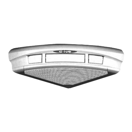
- Page 4 Name and funciton of each part Indoor unit Big/small air intake grill louver liquid crystral displayer Power plug drainage hose front grille remote controller Outdoor unit big handle Air in Air in -- 3 --...
-
Page 5: Remote Control Operation Procedure
Remote control operation procedure Name and Function-Remote control Note: Be sure that there are no obstructions between reciever and remote controller. Don’t drop or throw the remote control. Don’t let any liquid in the remote controller and put the remote controller directly under the sunlight or any place where is very hot. -
Page 6: Name And Function-Remote Control .(Remove The Cover)
Name and Function-Remote control .(Remove the cover) Note: This type of remote controller is a kind of new current controller. some buttons of the controller which are not available to this Air conditioner will not be described below. Operate on unmentioned buttons would not impact on the normal use. Liquid crystal displayer It shows all set contents. -
Page 7: Cool Mode Operation Procedure
COOL mode operation procedure According to difference between room temp., and set temp. microcomputer can control cooling on or not. If room temp. is higher than set temp. , compressor runs at COOL mode. If room temp. is lower than set temp., compressor stops and only indoor fan motor runs. SET TEMP. -
Page 8: Heat Mode Operation Procedure
HEAT mode operation procedure If room temp. is lower than set temp. , compressor runs at HEAT mode. If room temp. is higher than set temp., compressor and outdoor fan motor stop, only indoor fan motor runs a while and stop. SET TEMP. -
Page 9: Dry Mode Operation Procedure
DRY mode operation procedure If room temp. is lower than set temp. much more, compressor outdoor and indoor fan motor stop. If room temp. is between C of set temp., Air conditioner is drying. If room temp. is higher than set temp., it’s at COOL mode. SET TEMP. -
Page 10: Auto Mode Operation Procedure
AUTO mode operation procedure Under Auto mode operation, standard SET TEMP. is 25 C for COOL mode and 20 C for HEAT mode . 1. Plug in, Press 1/0 button, then air conditioner is turned on. 2. Press MODE button, set AUTO operation mode.According to room temp., microcomputer can automatically set... -
Page 11: Timer Mode Operation Procedure
TIMER mode operation procedure TIMER ON button At stopping, press TIME ON button, set ON TIME in range of 0 to 24 hour to start the unit automatially. cancel TIMER TIMER OFF button. At operating, press TIME OFF button. set OFF TIME in range of 0 to 24 hour to stop the unit automatically. - Page 12 SLEEP mode operation procedure As the unit is cooling or drying, if SLEEP operation is set, SET TEMP. would increase 1 C in 1 hour and 2 C in 2 hours. As the unit is heating, if SLEEP operation is set, SET TEMP. would decrease C in 1 hour and 2 C in 2 hours.
-
Page 13: How To Insert Batteries
How to insert batteries 1. Remove the cover from the back of the remote control. 2. Insert the two batteries (Two AAA dry - cell batteries) and press button “ACL”. 3. Re - attach the cover. NOTE: Don’t confuse the new and worn or different batteries. - Page 14 The optimum usage In order to save electricity,use it Conveniently and safely Set an appropriate room temparatrue,overcold is Be sure to turn off the harmful to health power socket when do not use in a long time. Clean the air filter and change a new one or apply to sunlight reqularly.
-
Page 15: User Notices
USER NOTICES Select the most appropriate temperature. It The airflow direction can be adjusted appro- can avoid the electricity wasting. priately. The louvers can be adjusted downward at heating operation, and upward at cooling op- eration. Don’t leave windows and doors open while the Don’t blow the wind to animals and plants air conditioner is on for a longtime. - Page 16 Care and Maintance Replacement of Air cleaner fastener of faster of rightside grill leftside grill button Central front panel hook (to avoid falling small air intake grill (rear) down of the grill) big air intake grill (front) Remove the air intake grill Remove the big air intake grill Remove the small air intake grill (front)
- Page 17 Clean the air intake grill. Notices: Don’t clean the surface with brush to avoid the damage of sur- face. If the grill is too dirty, you can wash it with mild detergent. Don’t dry it under direct sunlight or heater, or it will cause decol- oration and deformation of grill.
- Page 18 Attention Stop operation and turn off the power,or the It doesn’t need too much strength,making this high-speed moter may cause damage to manual as reference,or it will damage to inter- people. nal parts. Cleaning the air filter Disassemble the air filter Disassemble the front big air intake grill Stop operation and turn off Press two buttons,then slightly upward...
- Page 19 Installation and rechange of air cleaner The air cleaner combined with a low-temperature asepsis accelerant (white-green) and an active carbon(black). The former can deodorize and kill the bacillus of the air. The latter can adsorb the atom of air, enhancing the quality of air in the room.
-
Page 20: Troubleshooting
Troubleshooting Check the following points before requesting on service center of MUNDOCLIMA if the malfunction persist, it saves your time and money. Phenomenon Trouble Shooting Please Indoor unit does not Once the air conditioner is stopped, it will not oper- waiting operate immediately ate in approximately 3 minutes to protect itself. - Page 21 Immediately stop all operations and plug out, contact with service center of in following situations. Unusual noise can be heard during operation. Power fuse or switch often breaks. Carelessly splash water or something into air conditioner. Electrical lines and power plug are very hot. Wind blowing from the outlet smells terrible during operation.
-
Page 22: Technical Parameter
Technical parameter MODEL MUR-12C MUR-12H Function Cooling Heat pump type Assistant function collocated with air-cleaner 3500 3500 Cooling capacity (W) – 4000 Heating capacity (W) ~220V Rated voltage 50Hz Rated frequency 5.9/– 6.0/6.25 Rated current (A) Maximum input current (A) 1280/–... -
Page 23: Accessories And Installation Diagram
Accessories and Installation diagram Accessories (Check that all accessory parts are present before installation) Diagram Specification Memo Part name Wall-mounting frame Wireless remote contrller Battery 7 1.5V Power connection cable Signal control cable Heat pump type only Wall-mounting frame Tapping screw Fix the rear panel ST4.2X25 Packaged with... -
Page 24: Installation Dimension Diagram
Installation dimension diagram Important Notice 1. The unit should be installed by professionals under the quidance of this manual, ensuring the normal use of it. 2. Please contact with local service center before installation, the malfunction in the process of it. caused by no specific center may be diffiaut to deal with. 3. -
Page 25: Location Of Installation
Location of installation Indoor unit 1. The inlet and outlet should not be covered so that the outflow air can reach all parts of the room. 2. Install in a location where it is easy to connect to the outdoor unit. 3. -
Page 26: Install The Indoor Unit
Install the indoor unit Install the rear panel (unit:mm) Upper wall mounting frame Ripht wall mounting frame Left wall mounting frame Outlet of indoor unit Rightside wall- L e f t s i d e w a l l - mounting frame mounting frame Space to certring... -
Page 27: Installation Of Piping
Installation of piping 1. After installation of the wall mounting frame, to locate a declining pipeing hole. 2. Choose the suitable way for piping and stretch the pipe and wire. 3. Ensure to fix a piping-hole sleeve in order to protect piping and cable escape from damage while go through the wall. -
Page 28: Installation Of Drain Hose
The installation of indoor unit 1.first take off the air filter and the upper cover of electrical box before installation. 2.Hold the big handle then place indoor units on the hook of wall mountaing frame. Notice: Avoid the damage caused by the air conditioner collapse into the wall. Don’t clamp the louver 3.Move the air-conditioner in all directions, ensure they are held tightly. -
Page 29: Electric Connection
Electric connection 1. Take down the upper corer and wring cover of electrical box. 2. For KF(R)-28GJW/A300 KF(R)-35GJW/A300,KF(R)-40GJW/A300, first connect the blue wire of the power connection cable to the terminal “N(1)”, the brown one to “2”,the red one to 3(for KF(R)-40GJW/A300), the yellow-green one (earthing wire) connect to “... - Page 30 hole The installation of grill frame 1.Insert the hook of leftside grill into piping hole of indoor unit and hook of wall mount- ing frame.then fixed it with screws. 2.Insert the hook of right framework of grill hook and hole of indoor units, then fix it with screw * To installation of below pipe, fix use pin- cers or cutter to open holes in the obligation groove, then level off the cut with knife and...
-
Page 31: Install The Outdoor Unit
Install the outdoor unit Torqne wrench Installation of connect pipe 1.Align the center of piping with the correspond valve. 2.Screw in the plane nut by hand and then tighten the nut with spanner Spanner and torgue wrench refer as follows. Tightening torque(N.m) Hexangular nut tie in... - Page 32 The diagrams of unit wiring Power conncction cable Power conncction cable Singal cable The diagrams of unit wiring Power conncction cable Power conncction cable Singal cable Notice: Some mistakes in wiring will cause malfunction of some electrical parts. After the installation of cable, ensuring there is space between connection place and fixed place. -- 31 --...
-
Page 33: Leakage Test
Leakage test screndriver (unilateralism valve) 1. Take down the nut cover of turn off valve in the outdoor unit. gas pipe check valve 2. Face the central of tubing, tightering the pyramiclal nut with hand. 3. Tighten the pyramidal nut with spanner. 4. -
Page 34: Trial Operation
Test and Check Trial-operation 1. Peparation for trial-operation. (1) Don’t turn off the power before completion of all installation work. (2) The control circuitny must be conect correctly tiphtening all the electrical wire. (3) The cut-off valve of big or small pipe should loosen. (4) All the oddments especially the regulus and thrum should be cleared away npper cover of controller box from the unit. - Page 35 Contact Instructions The name and function of each part The name of each button and its function The name of each button and its function (open the cover) Cooling mode procedure Heating mode procedure Drying mode procedure Automatic operation mode procedure Timer operation mode procedure Sleep operation mode procedure Replace the batteries of the remote controller...
Need help?
Do you have a question about the MUR-12 H and is the answer not in the manual?
Questions and answers