Table of Contents
Advertisement
Quick Links
Advertisement
Table of Contents

Related Manuals for Redexim Verti-Drain 7113


Summary of Contents for Redexim Verti-Drain 7113
- Page 1 Operator and Parts Redexim manual Verti-Drain® Model 7113 Serial number: NOTE: IN ORDER TO ENSURE THE SAFE USE AND TO ACHIEVE THE BEST PERFORMANCE, IT IS ESSENTIAL THAT THIS OPERATORS MANUAL IS CAREFULLY READ BEFORE THE VERTI-DRAIN IS USED. 0718 English 911.120.410...
-
Page 2: Foreword
FOREWORD Congratulations on the purchase of your VERTI-DRAIN. To ensure the safe and lasting operations of this VERTI-DRAIN you (and anyone using the machine) should read and understand this user’s manual. A complete knowledge of the contents of the manual is necessary in order to ensure the safe use of this machine. -
Page 3: Safety Instruction
SAFETY INSTRUCTIONS Always use the VERTI-DRAIN with the correct tractor as described in the technical information The user is responsible for a safe Tractor/VERTI-DRAIN combination. The combination must be tested for noise, safety, risk and easy usage. It is also necessary to draw up user instructions. -
Page 4: Table Of Contents
CONTENTS Description Page Chapter Foreword Guarantee conditions Registration card Safety instruction Technical specification First setup, lifting machine from pallet General controls PTO length Use of PTO Slipclutch information and maintenance Working depth adjustment Tine angle adjustment Ground speed Starting procedures General usage of Verti-Drain 10.0 Transport of Verti-Drain... -
Page 5: Technical Specification
1.0 TECHNICAL SPECIFICATIONS Model 7113 Working width 1.34 mtr (54”) Working depth Up to 150 mm (6”) Tractor speed @ 500 rev’s at PTO Hole spacing 55 mm (2-1/8”) Up to 2.0 km/h (1.25 mph) Hole spacing 90 mm( 3 ½”) Up to 3.2 km/h (2.0 mph) Hole spacing 125mm(5”) Up to 4.3 km/h (2.7 mph) -
Page 6: First Setup, Lifting Machine From Pallet
2.0 FIRST SETUP, LIFTING MACHINE FROM PALLET The machine stands vertically up on the pallet. To remove the pallet and get the machine horizontal on the ground, handle as follows (see fig.1 ): 1. Open the rear cover 2. Connect a cable to lift point * ensure the cable/crane/lift truck can lift minimum 1000 Kg.(2200 lbs). -
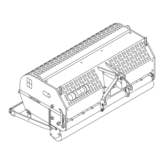
Page 7: General Controls
3.0 GENERAL CONTROLS In fig.2. some key details of the machine are shown, as follows: 1. Safety decal RA, before using machine read manual. Decal is located at the toolbox with manual and combi-tool. 2. Safety decal RB, Keep 4 mtr. (14' ) distance to the machine 3. -
Page 8: Pto
4.0 PTO. The PTO is a very important item. It drives the machine from the tractor and ensures the safe operations when correctly maintained and installed. The PTO shaft has its own CE certification. Read the PTO shaft manual, which is connected to the shaft itself 4.1 PTO LENGTH. -
Page 9: Use Of Pto
4.2 USE OF PTO For the correct use of the PTO, the following items need to be checked: 1. During work the angle of the joints may never exceed 30 degrees 2. The joints have to be in line all the time 3. -
Page 10: Working Depth Adjustment
5.0 WORKING DEPTH ADJUSTMENT The working depth can be adjusted when the machine is lifted from the ground as follows, see fig. 4: Unscrew nuts 1 at each side of the machine one turn. Screw spindle 3 in or out. Every revolution is 4 mm (0.160"). -
Page 11: Ground Speed
@ The angle of 90 degrees means that the tines penetrate perpendicular into the ground. This is only true if the machine is correctly set, see fig.1. If this isn' t correct a push force F, see fig 5. is applied, which can seriously damage the machine. -
Page 12: Starting Procedures
8.0 STARTING PROCEDURES The starting procedure is VERY important. If the start up is not done as described hereunder, serious damage to the machine may occur. Proceed as follows, see fig.7.: 1. Drive to the spot you want to start the operation. 2. -
Page 13: General Usage Of Verti-Drain
@ If nothing is done on the instability of the machine, serious troubles may arise afterwards. The machine is NOT protected against these circumstances on the long term. @ Never drive backwards with the tines in or close to the ground. @ NEVER drive backwards, when the lowest tines are less than 120 mm (5") above the ground. -
Page 14: Problem Analysis
12.0 PROBLEM ANALYSIS Machine vibrates Crankshaft rotates irregular Machine not at 90 degrees. PTO joint angles different. PTO joints not in line. Tough circumstances Adjust working depth. Use thinner/ shorter tines. If dry, irrigate first. Solid/ hollow tines are Wrong tine Change tine, use shorter one. -
Page 15: Maintenance
Look closely at machine Grease spindles front roller 14.0 EU-Declaration We, Redexim Utrechtseweg 127 3702 AC Zeist Holland, hereby declare fully on our authority that the product: VERTI-DRAIN 7113, WITH MACHINE NUMBER AS INDICATED ON THE MACHINE AND IN THIS MANUAL,... -
Page 16: Technical Information
15.0 TECHNICAL INFORMATION. Generally speaking, this Verti-Drain is not a complicated machine. A couple of technical items will be explained. If you still have questions, please contact your dealer, who is willing to assist you In the above fig.8. the torque setting for the several bolts/nuts is given and the timing of the crankshaft. -
Page 17: Torque Settings
15.1 TORQUE SETTINGS. In fig.8., the torque settings of the most important bolts/nuts are given. For the ones the torque setting is not mentioned, please be sure that they are tightened as a similar size bolt/nut would be tightened. If bolts/nuts are working themselves loose, loctite may be applied 15.2 THE CRANKSHAFT In fig.9. -
Page 18: Replacing Of A Crank And Crank Bearing
15.2.2. REPLACEMENT OF A CRANK WITH BEARING Replacing a crank is necessary when it is cracked or when the big end nuts start to come loose on a regular base. Either the crankbearing, the crankbearing fitting or the big end pin holes in the crank are damaged. -
Page 19: Options, Tines
16.0 OPTIONS, TINES Tines are essential for the correct working of the machine. Several tines are available for this machine, see the spare part pages for a total overview. Generally speaking, tines can be divided into two categories: Solids and Hollows. We advise using genuine tines, since they are fully adapted to the machine. -
Page 20: Hollow Tines
Use always tines with the same length and size. Replace a bent tine immediately. When this is not done, the machine can be unstable. Don’t use any thicker/ longer tines as what is offered by us. Shorter (worn) tines can be used in case shallower penetration is required. The machine doesn’t need to be adjusted that much at that time. - Page 21 Assembling the core collector itself: Assemble supports 17 with eye bolts 9 and nuts 10/11 to the main collector plate 1 Screw the side panels 2/3 with bolts 7 and Bushes 8 to the main collector plate 1 Assemble the rubber strip 12 with bolts 13, washers 14 and nuts 6 to the plate 1 Assemble all the sheet springs 4 , well aligned, to the main plate 1.
-
Page 22: Options, Turf Hold Down Kit
16.2 OPTIONS, TURF HOLD DOWN KIT. (Old set till serial number A00127) A Turf Hold Down Kit, # 9400045, can be used when the turf is coming loose. ASSEMBLING THE TURF HOLD DOWN KIT ( see fig.13): Assemble square nut 8 on the main beam 7. The nut should face vertical in the end. Tighten the nut, since it can stay all the time.
Need help?
Do you have a question about the Verti-Drain 7113 and is the answer not in the manual?
Questions and answers