Table of Contents
Advertisement
Advertisement
Table of Contents

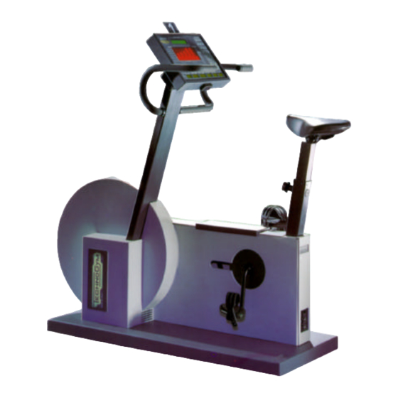
Summary of Contents for Technogym Bikerace
- Page 1 & ERVICE MAINTENANCE MANUAL . 1.1...
- Page 3 The information contained in this document is subject to change without notice. Technogym does not guarantee this documentation in any way. Technogym shall not be held responsible for any errors contained in this manual and declines all liability for accidents or damages resulting from the supply, characteristics or use of this manual.
-
Page 5: Table Of Contents
BIKERACE: Service & Maintenance Manual - rev. 1.1 Contents 1. GENERAL NOTICES ............................1.1 1.1. I ..............................1.1 NTRODUCTION 1.2. R ............................1.1 ECOMMENDATIONS 1.3. G ...................... 1.2 ENERAL RULES FOR REPAIR PROCEDURES 2. TECHNICAL CHARACTERISTICS ........................2.1 2.1. M ........................ - Page 6 BIKERACE: Service & Maintenance Manual - rev. 1.1 7.8. D ......................... 7.10 ISASSEMBLING THE ALTERNATOR 7.9. D ..........................7.11 ISASSEMBLING THE BELT 7.10. D ..........................7.13 ISASSEMBLING THE CHAIN 7.11. D .......................... 7.14 ISASSEMBLING THE PULLEY 7.12. D ....................7.15 ISASSEMBLING THE PEDAL CRANK GROUP 7.13.
-
Page 7: General Notices
1. GENERAL NOTICES 1.1. INTRODUCTION This document is reserved for Technogym Service technicians, and is intended to provide authorized personnel with the necessary information to correctly carry out repairs and maintenance. A thorough knowledge of the technical information contained in this manual is essential for completing the professional training of the operator. -
Page 8: General Rules For Repair Procedures
1. Always mark any parts or positions which may be confused with each other at the time of reassembly. 2. Use original Technogym spare parts and lubricants of the recommended brands. 3. Use special tools where specified. 4. Consult the Technical Newsletters, which may contain more up-to-date information on adjustments and maintenance than those contained in this manual. -
Page 9: Technical Characteristics
BIKERACE: Service & Maintenance Manual - rev. 1.1 2. TECHNICAL CHARACTERISTICS 2.1. MECHANICAL CHARACTERISTICS Width 58 cm Length 140 cm Height 140 cm Weight 86 Kg 2.2. ELECTRICAL CHARACTERISTICS Mains voltage 115 / 230 VAC Frequency 50 - 60 Hz Consumption ~ 60 Watt –... -
Page 10: Wiring Diagram
BIKERACE: Service & Maintenance Manual - rev. 1.1 2.5. WIRING DIAGRAM 2.5.1. ONNECTORS • CPU board name type of connector connection AMP MATE-N-LOCK 12-pin F. to alternator interface board AMP MODU II 4-pin M. to cardio receiver • Power supply... -
Page 11: Wiring
BIKERACE: Service & Maintenance Manual - rev. 1.1 • Alternator interface board name type of connector connection AMP MATE-N-LOCK 15-pin F. to CPU board AMP MATE-N-LOCK 6-pin F. to alternator AMP MODU I 4-pin M. to power supply AMP MODU I 8-pin M. - Page 12 BIKERACE: Service & Maintenance Manual - rev. 1.1 BK-3B: High voltage power supply ON-OFF Switch – Power supply ON-OFF Switch Signal Color Power supply Red Faston Live Blue Red Faston Neutral Black The above description of cable BK-3 is simplified and does not detail the ground node connections.
- Page 13 BIKERACE: Service & Maintenance Manual - rev. 1.1 BK-8: Serial ports cable Alternator interface board – Serial ports Alternator Signal Color Serial ports interface board Y – bus White Z – bus Orange A – bus Brown B – bus...
- Page 14 BIKERACE: Service & Maintenance Manual - rev. 1.1 Page intentionally left blank Page 2.6...
-
Page 15: Principles Of Operation
BIKERACE: Service & Maintenance Manual - rev. 1.1 3. PRINCIPLES OF OPERATION 3.1. BLOCK DIAGRAM The block diagram of the machine is shown in the figure below: CARDIO TRANSMITTER It is worn by the person using the machine, and transmits to the cardio receiver one pulse for every heart beat that is detected. - Page 16 BIKERACE: Service & Maintenance Manual - rev. 1.1 • Non-coded: this is the standard product; • Coded: this is the product which, utilizing Personal Coded Device technology, transmits the heart rate together with a code that identifies the transmitter in question. In this way, the coded receiver on the machine can identify the source of the heart rate signal, thereby avoiding interference problems.
- Page 17 BIKERACE: Service & Maintenance Manual - rev. 1.1 POWER SUPPLY Receives the mains voltage at its input and outputs the DC voltages (+5 Vdc, +12 Vdc and −12 Vdc) which supply the display and the alternator interface board. ALTERNATOR INTERFACE BOARD Receives from the display a square wave signal (PWM) whose frequency is proportional to the difficulty level setting, and converts it into an analogue excitation signal for the alternator.
-
Page 18: Alternator Control
BIKERACE: Service & Maintenance Manual - rev. 1.1 3.2. ALTERNATOR CONTROL 3.2.1. ECHANICS The movement of the pedals turns the pedal crank which by means of a chain transmits the motion to a pulley, which in turn transmits the motion to the alternator by means of a belt. -
Page 19: The Control Signals
BIKERACE: Service & Maintenance Manual - rev. 1.1 3.2.3. HE CONTROL SIGNALS The machine controls the difficulty level of the workout by means of the CPU board, the alternator interface board and the alternator, as illustrated in the figure below:... - Page 20 BIKERACE: Service & Maintenance Manual - rev. 1.1 • RPM Signal This is the speed signal output by the alternator. It enters the alternator interface board (pin 1-5 of connector CN2) and is a square wave which varies from –1 Vdc to a maximum value...
-
Page 21: Accessories
BIKERACE: Service & Maintenance Manual - rev. 1.1 4. ACCESSORIES 4.1. CONNECTING TO THE TGS The machine can be connected to the Technogym System by installing a special upgrade kit, which involves the following: • Installation of a special SW;... -
Page 22: Connecting To The Printer
The machine is pre-set for printing via the full duplex RS 485 port available on the serial ports panel. If the machine is equipped with Technogym System SW, the print function is not available. The printer is connected using a special cable, which can be ordered using code A419. This cable is equipped with an RS 485 to RS 232 serial converter. -
Page 23: Connecting To An External Device (Ecg And/Or Metabolic Monitor)
BIKERACE: Service & Maintenance Manual - rev. 1.1 4.3. CONNECTING TO AN EXTERNAL DEVICE (ECG AND/OR METABOLIC MONITOR) The medical version of the machine (HC800) can be connected to an external device (ECG and/or metabolic monitor) in order to perform exertion tests. The external device must provide an analogue output which is interfaced –... -
Page 24: Calibrating The Interface
BIKERACE: Service & Maintenance Manual - rev. 1.1 Because the machine is able to operate at power levels ranging from a minimum of 30 to a maximum of 500 Watts, it can therefore handle external analog signals ranging from 0.3 to 5 Vdc. -
Page 25: Installation Instructions
BIKERACE: Service & Maintenance Manual - rev. 1.1 5. INSTALLATION INSTRUCTIONS 5.1. SPECIFICATIONS AND REQUIREMENTS For correct machine installation, make sure that: 1. The machine is installed on a level surface that is free of vibrations and has sufficient carrying capacity for the combined weight of the machine and user. -
Page 26: First Power-On
BIKERACE: Service & Maintenance Manual - rev. 1.1 5.3. FIRST POWER-ON After completing the installation procedure, the machine is ready to be powered up. To turn on the machine, simply toggle the on/off switch from the 0 position to the 1 position. -
Page 27: Troubleshooting
BIKERACE: Service & Maintenance Manual - rev. 1.1 6. TROUBLESHOOTING The troubleshooting procedures are shown in the form of flow charts. In order to facilitate consultation, the following standard box shapes are used. This type of box is the START point of the troubleshooting procedure. It typically contains a description of the problem or malfunction. -
Page 28: The Display Does Not Illuminate
BIKERACE: Service & Maintenance Manual - rev. 1.1 6.1. THE DISPLAY DOES NOT ILLUMINATE This error occurs when the supply voltage fails to reach the display. THE DISPLAY DOES NOT ILLUMINATE Are the fuses OK? Replace the blown fuses Is the mains lead OK? - Page 29 BIKERACE: Service & Maintenance Manual - rev. 1.1 Replace the power Are DC voltages output by the supply power supply correct? Do all DC voltages reach the Replace the CPU board display? Do all DC voltages reach the Replace cable BK-6...
- Page 30 BIKERACE: Service & Maintenance Manual - rev. 1.1 As for step (1) but with the tester between terminals L1 and N1 of the input socket / on-off switch block. Slightly lift connector CN2 on the power supply to access the pins with the tester probes.
-
Page 31: There Is No Resistance
BIKERACE: Service & Maintenance Manual - rev. 1.1 6.2. THERE IS NO RESISTANCE This error can be caused by absence of the speed signal, problems with the excitation circuit, overheating of the alternator or defective alternator brushes. THERE IS NO... -
Page 32: The Resistance Is Incorrect
BIKERACE: Service & Maintenance Manual - rev. 1.1 6.3. THE RESISTANCE IS INCORRECT The resistance is incorrect if the alternator does not receive the correct excitation signal or if the power resistor is defective. RESISTANCE IS INCORRECT Is the alternator excitation... - Page 33 BIKERACE: Service & Maintenance Manual - rev. 1.1 Follow the procedure step by step to correctly diagnose the problem. Take particular care with the checks highlighted by circled numbers, which are described in detail below: Place the tester probes between the orange (positive) and black (negative) cables on the alternator.
-
Page 34: The Rpm Value Is Incorrect
BIKERACE: Service & Maintenance Manual - rev. 1.1 6.4. THE RPM VALUE IS INCORRECT This error occurs when there are problems with the RPM signal output by the alternator. THE RPM VALUE IS INCORRECT Is the RPM wire of cable... - Page 35 BIKERACE: Service & Maintenance Manual - rev. 1.1 Follow the procedure step by step to correctly diagnose the problem. Take particular care with the checks highlighted by circled numbers, which are described in detail below: Check whether the black and violet wires, which connect the alternator to pins 1 and 5 of CN2 on the alternator interface board, are correctly connected.
-
Page 36: The Machine Does Not Print
BIKERACE: Service & Maintenance Manual - rev. 1.1 6.5. THE MACHINE DOES NOT PRINT This error occurs when there are HW problems, or if the machine has not been configured correctly. Always check that the printer itself is working correctly first. - Page 37 BIKERACE: Service & Maintenance Manual - rev. 1.1 Connect the tester to the output connector of printer cable A419, and connect the other end to the machine. Choose any workout program: as soon as the last value entered has been confirmed, the workout starts and the machine immediately transmits the data via the serial port.
-
Page 38: The Machine Does Not Operate In Master - Slave Mode
BIKERACE: Service & Maintenance Manual - rev. 1.1 6.6. THE MACHINE DOES NOT OPERATE IN MASTER - SLAVE MODE This error is due to problems on the Master - Slave control signal. THE MACHINE DOES NOT OPERATE IN MASTER - SLAVE MODE... - Page 39 BIKERACE: Service & Maintenance Manual - rev. 1.1 Are the signals output by the Replace cable BK-1 Replace the CPU board serial port on the CPU board correct? Follow the step by step procedure to correctly diagnose the problem. Take particular care with the checks highlighted by circled numbers, which are described in detail below: Disconnect any race cables linking the machines before performing these checks.
-
Page 40: There Is No Heart Rate Signal
BIKERACE: Service & Maintenance Manual - rev. 1.1 6.7. THERE IS NO HEART RATE SIGNAL This error occurs when the receiver is not working or when it does not receive the power supply from the CPU board. THERE IS NO... -
Page 41: The Heart Rate Signal Is Incorrect
BIKERACE: Service & Maintenance Manual - rev. 1.1 6.8. THE HEART RATE SIGNAL IS INCORRECT The machine displays this message when the receiver is disturbed by electromagnetic noise in the surrounding environment. In some cases, the machine may show the message “Err” on the heart rate display. - Page 42 BIKERACE: Service & Maintenance Manual - rev. 1.1 Is the transmitter in good Use a known good working order? transmitter Is the transmitter always Keep the transmitter within a distance of 80 cm within the minimum from the receiver? reception distance Change the receiver Follow the procedure step by step to correctly diagnose the problem.
-
Page 43: Disassembly Of Components
BIKERACE: Service & Maintenance Manual - rev. 1.1 7. DISASSEMBLY OF COMPONENTS 7.1. DISASSEMBLING THE DISPLAY 1. Turn off the machine and unplug the mains lead from the wall outlet. 2. Back off the 5 screws a using a 4-mm hex T wrench. -
Page 44: Disassembling The Eprom
BIKERACE: Service & Maintenance Manual - rev. 1.1 7.2. DISASSEMBLING THE EPROM 1. Turn off the machine and unplug the mains lead from the wall outlet. 2. Back off the 4 fixing screws a of the protective cover using a small Philips screwdriver. -
Page 45: Disassembling The Cpu Board
BIKERACE: Service & Maintenance Manual - rev. 1.1 7.3. DISASSEMBLING THE CPU BOARD 1. Turn off the machine and unplug the mains lead from the wall outlet. 2. Back off the 4 fixing screws a of the protective cover using a small Philips screwdriver. - Page 46 BIKERACE: Service & Maintenance Manual - rev. 1.1 Rest the keyboard – electronic circuit boards group on a work bench: 7. Disconnect connectors e. 8. Back off the 6 studs f using a 7-mm wrench. Figure 7.3-4 9. Separate the CPU board g from the LED board h by flipping it over toward the left, being careful not to damage cable strip i.
-
Page 47: Disassembling The Keyboard
BIKERACE: Service & Maintenance Manual - rev. 1.1 7.4. DISASSEMBLING THE KEYBOARD 1. Turn off the machine and unplug the mains lead from the wall outlet. 2. Back off the 4 fixing screws a of the protective cover using a small Philips screwdriver. - Page 48 BIKERACE: Service & Maintenance Manual - rev. 1.1 Rest the keyboard – electronic circuit boards group on a work bench: 7. Unplug the keyboard connector. 8. Use a sharp tool to lift up a corner of the KEYBOARD and detach it.
-
Page 49: Disassembling The Cardio Receiver
BIKERACE: Service & Maintenance Manual - rev. 1.1 7.5. DISASSEMBLING THE CARDIO RECEIVER 1. Turn off the machine and unplug the mains lead from the wall outlet. If the receiver is positioned under the display: 2. Use a flat blade screwdriver to open the box a which contains the RECEIVER. -
Page 50: Disassembling The Right And Left Side Guards
BIKERACE: Service & Maintenance Manual - rev. 1.1 7.6. DISASSEMBLING THE RIGHT AND LEFT SIDE GUARDS 1. Turn off the machine and unplug the mains lead from the wall outlet. 2. Unscrew the 12 self-tapping screws a which fix the LEFT SIDE GUARD using a large Phillips screwdriver. -
Page 51: Disassembling The Electronic Circuit Boards
BIKERACE: Service & Maintenance Manual - rev. 1.1 7.7. DISASSEMBLING THE ELECTRONIC CIRCUIT BOARDS Carry out the procedure described in paragraph 7.6. “Disassembling the right and left ”, removing only the right side guard. 1. Cut the straps securing the cables to the protective grille. -
Page 52: Disassembling The Alternator
BIKERACE: Service & Maintenance Manual - rev. 1.1 7.8. DISASSEMBLING THE ALTERNATOR Carry out the procedure described in paragraph 7.6. “Disassembling the right and left side guards”. 1. Disconnect cables from ALTERNATOR. 2. Loosen nut a of belt tension rod b using a 17- mm wrench. -
Page 53: Disassembling The Belt
BIKERACE: Service & Maintenance Manual - rev. 1.1 7.9. DISASSEMBLING THE BELT Carry out the procedure described in paragraph 7.6. “Disassembling the right and left side guards”. 1. Loosen nut a of belt tension rod b using a 17- mm wrench. - Page 54 BIKERACE: Service & Maintenance Manual - rev. 1.1 From the left-hand side of the machine: 8. Remove BELT g from the guide of pulley h. 9. Remove snap ring i using the special pliers. 10. In the case of a non-threaded pin: use a...
-
Page 55: Disassembling The Chain
BIKERACE: Service & Maintenance Manual - rev. 1.1 7.10. DISASSEMBLING THE CHAIN Carry out the procedures described in paragraphs 7.6. “Disassembling the right and left side guards”. 1. Turn the CHAIN until the connecting link a is on the sprocket wheel b. -
Page 56: Disassembling The Pulley
BIKERACE: Service & Maintenance Manual - rev. 1.1 7.11. DISASSEMBLING THE PULLEY Carry out the procedures described in paragraphs 7.6. “Disassembling the right and left side guards”, 7.9. “Disassembling the belt ” and 7.10. “Disassembling the chain”. Regardless of the type of pin: 1. -
Page 57: Disassembling The Pedal Crank Group
BIKERACE: Service & Maintenance Manual - rev. 1.1 7.12. DISASSEMBLING THE PEDAL CRANK GROUP Carry out the procedures described in paragraphs 7.6. “Disassembling the right and left side guards” and 7.10. “Disassembling the chain”. 1. Unscrew the left pedal a using a 15-mm wrench. -
Page 58: Disassembling The Alternator Brushes
BIKERACE: Service & Maintenance Manual - rev. 1.1 7.13. DISASSEMBLING THE ALTERNATOR BRUSHES Carry out the procedures described in paragraph 7.6. “Disassembling the right and left side guards”, removing only the left side guard. 1. Disconnect cable a from the alternator. -
Page 59: Adjustments
BIKERACE: Service & Maintenance Manual - rev. 1.1 8. ADJUSTMENTS 8.1. ALIGNING THE BELT Carry out the procedures described in paragraphs 7.6. “Disassembling the right and left side guards”. 1. Back off the lock nut a on alternator pivot b using a 19-mm wrench. -
Page 60: Belt Tension
BIKERACE: Service & Maintenance Manual - rev. 1.1 8.2. BELT TENSION Carry out the procedures described in paragraph 7.6. “Disassembling the right and left side guards”. 1. Back off lock nut of alternator pivot a using a 19-mm wrench. 2. Back off dowel b of alternator pivot a. -
Page 61: Chain Alignment
BIKERACE: Service & Maintenance Manual - rev. 1.1 8.3. CHAIN ALIGNMENT Machine version with non threaded pin: Carry out the procedures described in paragraph 7.6. “Disassembling the right and left side guards”. 1. From both sides of the machine, use a marker pen to fix a reference point between cam a and the frame. - Page 62 BIKERACE: Service & Maintenance Manual - rev. 1.1 Machine version with threaded pin: Carry out the procedures described in paragraph 7.6. “Disassembling the right and left side guards”. Working from the right-hand side: 1. Unscrew the screw e using a 4-mm hex T wrench.
-
Page 63: Chain Tension
BIKERACE: Service & Maintenance Manual - rev. 1.1 8.4. CHAIN TENSION Carry out the procedures described in paragraph 7.6. “Disassembling the right and left side guards”. From both sides of the frame: 1. Back off the 2 screws a which fix cam b onto the frame using a 4-mm hex T wrench. -
Page 64: Play Of Saddle Stem
BIKERACE: Service & Maintenance Manual - rev. 1.1 8.5. PLAY OF SADDLE STEM 1. Turn off the machine and unplug the mains lead from the wall outlet. 2. Raise the rubber protection a. On each of the 4 fixing points: 3. -
Page 65: Wear Of Alternator Brushes
BIKERACE: Service & Maintenance Manual - rev. 1.1 8.6. WEAR OF ALTERNATOR BRUSHES Carry out the procedures described in paragraph 7.13. “Disassembling the alternator brushes”. Inspect the 2 brushes for wear, referring to the figures at left and to the descriptions below: •... -
Page 66: Play Of The Pedal Group
BIKERACE: Service & Maintenance Manual - rev. 1.1 8.7. PLAY OF THE PEDAL GROUP Carry out the procedures described in paragraph 7.12. “Disassembling the pedal crank group” up until step 4 . 1. Adjust the 2 ring nuts a using 36-mm wrenches until the pedal group is securely fixed. -
Page 67: Adjusting The Lcd Backlighting
BIKERACE: Service & Maintenance Manual - rev. 1.1 8.8. ADJUSTING THE LCD BACKLIGHTING After the machine has been switched on for at least 1 hour, without switching it off: 1. Adjust trimmer P1 on the back of the display to obtain the desired level of LCD luminosity. -
Page 68: Adjusting The Buzzer Tone
BIKERACE: Service & Maintenance Manual - rev. 1.1 8.9. ADJUSTING THE BUZZER TONE Turn on the machine and, when the buzzer is sounded during the start-up procedure: 1. Adjust trimmer P2 on the back of the display to obtain the desired buzzer tone. -
Page 69: Configuring The Machine
BIKERACE: Service & Maintenance Manual - rev. 1.1 9. CONFIGURING THE MACHINE 9.1. MACHINE HW CONFIGURATION The HW configuration of the machine is set using the 2 banks of dip-switches on the back of the CPU board, according to the tables below: 9.1.1. - Page 70 BIKERACE: Service & Maintenance Manual - rev. 1.1 Page intentionally left blank Page 9.2...
-
Page 71: Scheduled Maintenance
BIKERACE: Service & Maintenance Manual - rev. 1.1 10. SCHEDULED MAINTENANCE To keep the machine in perfect working order and prevent the risk of malfunction, it is necessary to perform the scheduled maintenance operations set out in the table below. There are 3 basic types of maintenance operations: •... -
Page 72: Internal Cleaning Operations
BIKERACE: Service & Maintenance Manual - rev. 1.1 10.2. INTERNAL CLEANING OPERATIONS These operations can be carried out by the owner of the machine and do not require any special skills. The internal cleaning procedures are simple cleaning operations aimed at keeping the interior of the machine clean. -
Page 73: Special Maintenance Operations
10.3. SPECIAL MAINTENANCE OPERATIONS These operations can only be carried out by a qualified technician specifically trained by Technogym and authorized to carry out machine installation and adjustments, as well as special maintenance operations or repairs which require special knowledge of the machine, its operation, safety systems and working procedures. -
Page 74: Checking The State Of Wear Of The Chain
BIKERACE: Service & Maintenance Manual - rev. 1.1 10.3.6. C HECKING THE STATE OF WEAR OF THE CHAIN 1. Check the state wear of the chain, inspecting its entire length. Replace if links are jammed and/or have excessive play. 2. Check the tension and the alignment of the chain. Adjust them if necessary. -
Page 75: Appendix
11. APPENDIX 11.1. TECHNICAL NOTES ON CARDIO RECEIVERS Technogym utilizes Polar technology for measuring the heart rate frequency of the person training on the machine. The Polar system consists of: • a transmitter, worn by the person training on the machine, which uses 2 electrodes to detect the electrical activity of the heart and transmits the measured heart rate by sending an electromagnetic signal at a frequency of 5 kHz. -
Page 76: Type Of Asic
BIKERACE: Service & Maintenance Manual - rev. 1.1 There are 3 types of problems which can typically occur on the heart rate signal: • interference caused by disturbances from sources of electromagnetic noise. These problems cause the heart rate signal to deviate from the rear value, typically making it higher;... -
Page 77: Reducing Receiver Sensitivity
BIKERACE: Service & Maintenance Manual - rev. 1.1 of the receiver (detected by the coil) whereas they have no effect on digital components such as the CPU receiver connecting cable. Electromagnetic interference can take different forms: on the one hand, the receiver may detect and hence generate spurious transients or periodic noise pulse, or on the other hand the receiver may become saturated. -
Page 78: Mechanical Vibrations
BIKERACE: Service & Maintenance Manual - rev. 1.1 Sensitivity is reduced by soldering a resistor in parallel with the coil. Normally, the receiver already has a 15 KOhm resistor mounted in parallel with the coil, however it is advisable to check for its presence. -
Page 79: Routing Of Cables
BIKERACE: Service & Maintenance Manual - rev. 1.1 • the receiver must be directed in such a way that its axis of reception is parallel to that of the transmitter, as shown in the figure below: Figure 11.1-2 Please note that even small departures from the above specifications may considerably impair the accuracy of reception. -
Page 80: Personal Coded Device
11.2. PERSONAL CODED DEVICE Starting from April 1999, the machine can be equipped with a new heart rate receiver based on the PERSONAL CODED DEVICE technology developed exclusively by Technogym in conjunction with POLAR. Thanks to a special receiver installed on the machine, and using a new “coded” chest strap, the machine receives only the heart rate signal from its own user. -
Page 81: Upgrade Of Machines Already Installed
BIKERACE: Service & Maintenance Manual - rev. 1.1 Code T (msec) At the start of the training session, the coded receiver first of all seeks to detect a coded signal for a maximum of 10 seconds. This is done in reduced sensitivity mode to avoid receiving a signal from users on adjacent machines. -
Page 82: Special Functions
BIKERACE: Service & Maintenance Manual - rev. 1.1 11.3. SPECIAL FUNCTIONS Below is a list of the special functions and passwords available on the machine: 11.3.1. D ISPLAYING THE SELECTED TYPE OF ALTERNATOR Simultaneously press the 1-4-7 keys, the LCD will show: •... - Page 84 TECHNOGYM S.p.A. Via G. Perticari, 20 47035 Gambettola (FC) ITALIA Tel.: +39-0547-650438 Fax: +39-0547-650150 e-mail: service@technogym.com 0SMM0019-ING...
Need help?
Do you have a question about the Bikerace and is the answer not in the manual?
Questions and answers
CHE TIPO DI FASCIA CARDIO disponibili oggi sul mercato per questo tipo di cyclette
There are two types of heart rate transmitters available for the Technogym Bikerace. These transmitters are worn by the user and send one pulse for each detected heartbeat to the cardio receiver.
This answer is automatically generated