Table of Contents
Advertisement
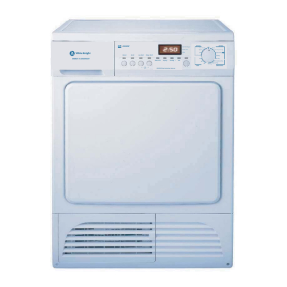
SERVICE MANUAL
Condenser Tumble Dryer
White Knight - B96G8W
Error Codes & PCB Test
Note: Please read before servicing the unit. Any problems: contact your service centre
8kg
UK
8kg
B96G8W
Buzzer
Quick
Low Heat
Delay Start
ENERGY B CONDENSER
Child Lock
IMPORTANT: Read instructions before use
Exploded Views
Wiring Diagram
Parts List
Disassembly Guide
May 2017
SPECIAL
COTTON
Heat Exchanger
OFF
Cool Tumble
Denim
Bottle Full
Refresh
Extra Cupboard Dry
Filter
Silk
Cupboard Dry
Underwear
Mid Dry
30'
Iron Dry
Drying
Cooling
End
Extra Cupboard Dry
60'
90'
Cupboard Dry
Iron Dry
TIME
SYNTHETICS
Advertisement
Table of Contents

Related Manuals for White Knight B96G8W


Summary of Contents for White Knight B96G8W
-
Page 1: Parts List
SERVICE MANUAL Condenser Tumble Dryer White Knight - B96G8W B96G8W SPECIAL COTTON Heat Exchanger Cool Tumble Denim Bottle Full Refresh Extra Cupboard Dry Filter Silk Cupboard Dry Buzzer Quick Low Heat Delay Start Underwear Mid Dry ENERGY B CONDENSER Iron Dry... - Page 2 Exploded View 1 - General Description Exploded View 2 - Control Panel Assembly Exploded View 3 - Door Assembly...
- Page 3 Exploded View 4 - Water Bottle Assembly Exploded View 5 - Plinth Assembly Exploded View 6 - Drum Assembly Exploded View 7 - Front Panel...
- Page 4 Exploded View 8 - Front Housing Assembly 64 65 68 69 70 71 Exploded View 9 - Drum Rear Assembly Exploded View 10 - Base Assembly...
- Page 5 Electric diagram...
- Page 6 White Knight B96G8W Item Part Description Crosslee Part No. Supplier Part No. GENERAL DESCRIPTION ‐ EXPLODED VIEW 1 Door Assembly (Includes items 26 to 36) 4213 092 69351 DC80S1E.5.1(182) Plinth Assembly (Includes items 43 to 46) 4213 092 69361 DC80S1E.6(182)
- Page 7 FRONT PANEL ASSEMBLY ‐ EXPLODED VIEW 7 Front Panel Available as part of item 3 DC80S1E.5.2‐1(182) Door Lock Assembly 4213 092 69491 DC80S1E.5.2‐4(182) FRONT HOUSING ASSEMBLY ‐ EXPLODED VIEW 8 Microswitch Rocker DC80S1E.1.2‐13(182) Microswitch Spring ( includes item 56) 4213 092 71311 DC80S1E.1.2‐14(182) Microswitch Bracket DC80S1E.1.2‐12(182)
- Page 8 Error Codes – B96G8W Display Error/Fault Thermistor on heater, O/C or S/C Heater fault Thermistor in exhaust, O/C or S/C Door open or heat exchanger not fitted properly Program selection error...
- Page 9 B96G8W – PCB quick check LED10 LED11 LED12 LED9 LED8 LED7 LED6 LED5 LED4 LED3 LED2 LED1 Rotary Switch LED1 Start/Pause LED7 Low Heat Start/Pause LED2 LED8 Quick Delay Start LED3 Cooling LED9 Buzzer Low Heat LED4 Drying LED10 (if fitted)
- Page 10 The main display should show ‘1A0’. Open the dryer door and place Press SW2 (Start/Pause) hands across the sensing rods. The main display should scroll down to Sensing rods button display a value in the range of ‘100’ to ‘105’. Remove hand and after a second, the display should scroll back up to ‘1A0’.
- Page 11 B96G8W AND B93G8W DISASSEMBLY GUIDE Fixings: There are five screw types associated with this appliance: A – general common fixing screw, found in a multitude of locations B – Countersunk screw, found holding metal front panel (part 51) to the plastic front housing (part 67) C –...
- Page 12 To disassemble the appliance: 1) Remove 2 screws (A) from the rear of the top cover. Lift the rear of the top cover and slide towards the rear of the dryer. 2) Remove the bottle from the front of the appliance. 3) Remove 3 screws (A) from the top of the control panel.
- Page 13 5) Open the dryer door and remove the 5 screws (B), leaving the single screw above the door catch and the four screws in the door hinges in position. 6) Shut the door and remove the 2 screws (C) from the bottom of the front panel.
- Page 14 7) In the top of the dryer, undo the two screws (C) holding the loom harness to the side panel. 8) Remove the wiring harness from the 4 cable clips on the side panel. 9) Remove the brown wire and two blue wires that are part of the wiring harness from the...
- Page 15 10) Remove 14 screws (A) from the backpanel assembly. Lift the backpanel away. 11) Remove 3 screws (A) from the rear of the right hand side panel.
- Page 16 12) Remove 1 top cover support screw (D) from the top of the right hand side panel. 13) Remove 5 screws (A) from the front of the right hand side panel. The right hand side panel should now be free and come away from the dryer.
- Page 17 14) De‐tension the drive belt by lifting the spring out of the plastic base of the dryer. 15) At the rear of the dryer, unclip the wiring harness from the three cable clips and un‐ couple the 6‐way connector which goes to the heater.
- Page 18 16) Unclip the two pipes from the 3 pipe clips on the rear right hand side of the dryer. 17) On the drum rear assembly, undo 3 screws (A) which attach the drum rear assembly to the re‐circulating air duct.
- Page 19 18) Remove 2 screws (A) holding the drum rear assembly to the left hand side panel. Lift the drum rear assembly away. 19) Remove the belt from the top of the drum (note that the belt is still on the motor shaft at this stage).
- Page 20 21) Unclip the two pipes from the rear of the bottle housing. 22) Unscrew 2 screws (A) from the left hand side panel which hold the bottle housing in position. 23) Unscrew 1 screw (A) from the bottom of the left hand side panel.
- Page 21 24) Unscrew 1 top cover support screw (D) from the top of the left hand side panel. 25) Unscrew 5 screws (A) from the front of the left hand side panel. The left hand side panel can now come away from the dryer.
- Page 22 27) Using a 14mm socket, remove the nut holding the cooling fan in place. Remove the washer from the fan and lift the cooling fan from the motor shaft. 28) Remove the cooling fan cover by unclipping the right and left hand sides of the cover.
- Page 23 31) Remove the 6 screws (A) from the top of the re‐ circulating air duct. Remove the air duct by unclipping twice on the right hand side and twice on the left hand side of the appliance. 32) Remove the 4 screws (A) from the top of the re‐...
- Page 24 34) Unscrew the 4 screws (E) from the top of the motor mounting brackets. 35) Remove the motor mounting brackets and aside. Remove the re‐circulating fan by using a 14mm socket. 36) Remove the cir‐clip from the motor which holds the belt pulley in place.
- Page 25 38) Remove the wiring connector from the float microswitch. 39) Unclip the wiring harness from the pump cover and pump. 40) Remove the 2 pipes from the pump cover.
- Page 26 41) Remove the 3 screws (A) from the pump cover. Unclip the sump cover in the 4 positions and remove. 42) Remove the pump by pushing it downwards out of the pump cover.
- Page 27 www.whiteknightspares.co.uk www.whiteknightrange.co.uk...
Need help?
Do you have a question about the B96G8W and is the answer not in the manual?
Questions and answers