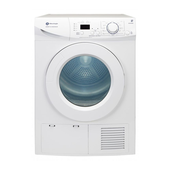
Summary of Contents for White Knight B96M8W
- Page 1 SERVICE MANUAL Condenser Tumble Dryer White Knight - B96M8W Trouble Shooting & Safety Guide Wiring Diagram Exploded Views Parts List September 2016 Note: Please read before servicing the unit. Any problems: contact your service centre...
- Page 2 CONTENTS – B96M8W 2. User error checklist 3. Control panel connection diagram 3.1 Lack of display on control panel 3.2 Drum does not turn but the control panel displays correctly 3.3 Heating system failure 3.4 The drum turns but the appliance fails to dry 3.5 The dryer makes an abnormal noise when operating...
-
Page 3: Control Panel Connection Diagram
3. Control panel connection diagram P0 Live and neutral P1 Load moisture sensor P2 Motor L + heater (700W) L P3 Drum light and pump P4 Door switch P5 Heater N+ motor N P6 Heater (1600W) L P7 Water level sensor, Inlet thermistor and Exhaust thermistor... -
Page 4: Fault Finding
3. FAULT FINDING 3.1 Lack of display on control panel Check if power is getting to the appliance Check fuse for continuity Replace fuse Switch off the appliance Check power cord and Replace the mains cable Check for 230V between loom harness for damage or loom harness as necessary pins P0 on PCB... - Page 5 Check loose connections or damage to loom Re-assemble or replace the loom 3.3 The heating system does not work Check if the “cool” program is in operation Re-test the appliance in a heating program Check if terminal P4 is loose Re-attach terminals Check if the loom is damaged Replace the loom harness...
- Page 6 3.5 The dryer makes an abnormal noise when operating Check to find the source of the noise Check if the screws holding the lifter to the drum Tighten the screws accordingly are loose Is the front support wheel damaged Replace the front support wheel subassembly including shaft Is the tension spring connected between the Reassemble the tension spring...
- Page 7 3.7 The LED displays when the dryer is operating Check if the bottle is full Empty the bottle Check if the pump is connected correctly Attach the terminals accordingly or replace the loom Check PCB for any signs of damage Check connections on PCB and replace if necessary Check if the pump is damaged or blocked Replace or clean the pump...
- Page 8 4.2 Disassembly methods 1. Control panel assembly disassembly 1. Unfasten the two screws at the rear of the top cover and slide top cover backwards 2. Remove the bottle 3. Remove 4 screws at the front of the dryer from the control panel and cross brace 4.
- Page 9 6. Remove the screws holding the PCB to the control panel. The PCB’s can be removed by unscrewing and unclipping where necessary. 2. Disassembling the RFI filter and water level sensor Disassembling the RFI filter: Remove the loom terminals from the filter. Unfasten the two screws from the filter in order to remove the filter from the upper bracket.
- Page 10 4) Push the two pins of the hinge to separate the hinge.. 4. Disassembling the heater 1) Remove the screws from the rear panel 2) Remove the screws from the air ductwork below the heater 3) Remove the top cover by unscrewing the screws at the back of the appliance.
- Page 11 6) Remove the cable clamp holding the wires to the backpanel 7) Remove the screws from the heater 5. Disassembling the drum 1) With the side panels and the top cover of the appliance removed, remove the bracing struts between the front and backpanels. Remove the screws which hold the metal backpanel to the plastic base.
- Page 12 5) Remove the nut with adjustable wrench or similar 6) Remove the drum shaft ring 7) Remove the backpanel from the drum 8) Remove the other two shaft rings...
- Page 13 5. Wiring Diagram 1-Pump 2-Drum light 3-Door Switch 4-Moisture level sensor 5-Mains cable 6-RFI filter 7-Motor 8-Capacitor 9-Heater 10-Inlet thermistor 11-Water level sensor 12-Exhaust thermistor 6. Exploded View...
- Page 14 Exploded View Base...
- Page 15 Exploded View Front Support...
- Page 16 Exploded View Control Panel & Water Bottle...
- Page 17 Exploded View Drum...
- Page 18 Exploded View Front Panel...
- Page 19 Exploded View Door...
- Page 20 Parts for Model White Knight B96M8W ITEM No DESCRIPTION CODE BOM code Handle Assembly 4213 092 69251 301160760440 Base Assembly NOT AVAILABLE 301160760035 1.2.1 Condenser Cover 4213 092 65211 301160700025 1.2.2 Sump Cover 4213 092 65341 301160700024 Capacitor 4213 092 65291...
- Page 21 Door Assembly - up to WK1537 4213 092 64901 301160700018 Door Assembly - from WK1538 4213 092 69281 12138200A02721 Outer Frame 4213 092 64911 301160700053 Protect Cover 4213 092 64921 301160700057 Inner Ring Seal 4213 092 64941 302760700005 Door Plunger - up to WK1537 4213 092 64961 302960700011 Door Plunger - from WK1538...


Need help?
Do you have a question about the B96M8W and is the answer not in the manual?
Questions and answers