
Related Manuals for SEA 7157

Summary of Contents for SEA 7157
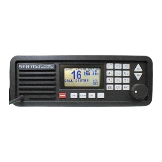
- Page 1 SEA 7157 OPERATOR’S MANUAL 25W VHF/DSC RADIOTELEPHONE Software Version: Ver. 1.10 11, Feb 1999...
-
Page 3: Table Of Contents
TABLE OF CONTENTS GENERAL OPERATIONS ................1 Technical Specifications...................1 General Information ..................2 LCD Display Characters...................3 Front Panel Controls..................3 Basic Operation ....................4 Turning The Radio ON..................5 Selecting A Channel List ..................5 Selecting A Channel ..................6 Adjusting The Squelch ..................6 Channel 16 Key ....................7 Operating The Transmitter ................7 ADVANCED RADIO OPERATIONS..............8 Selecting The Radio Menu ................8... - Page 4 TABLE OF CONTENTS GMDSS CLASS A CALLS ................21 Details Of A “Class A” Call ................21 Distress Call....................24 All Ships Calls ....................25 Geographical Area Calls.................26 Individual / Group Calls .................27 Phone Calls.....................28 PROGRAMMING DSC OPTIONS..............29 DSC Programming..................29 Setting The Date & Time................29 Programming The DSC ID (MMSI) ...............30 Programming The Navigation Interface ............30 Programming Options..................31...
-
Page 6: General Operations
GENERAL OPERATIONS TECHNICAL SPECIFICATIONS DIMENSIONS: 3.9” H x 10.5” W x 10.9” D 99mm H x 265mm W x 278mm D WEIGHT: 7.75 Lbs. 3.5 Kgs. ELECTRICAL: Type Acceptance FCC Parts 80, 15 GMDSS (Para 80.1101) EIA RS-204C, RS-152B FCC Identifier BZ6SEA7157 Frequency Range (TX) 155 - 159 MHz... -
Page 7: General Information
RADIO PROTECTION The chassis of the SEA 7157 is not connected to either supply rail. This allows a direct connection to the ship’s earth connection for voltage and RF interference protection. In the event that the input voltage is reversed, the line fuse (7.5 amp for 12 volt operation or 5 amp for 24 volt operation) will blow. -
Page 8: Lcd Display Characters
GENERAL OPERATIONS LCD DISPLAY CHARACTERS The radio is in TRANSMIT. Indicates the radio will transmit using 25 watts of output power. Indicates the radio will transmit using 1 watt of output power. The radio is set for maximum receive sensitivity. The radio is set for local receive sensitivity. -
Page 9: Basic Operation
PUBLIC CORR e.g. Your SEA 7157 is now set to transmit and receive on the selected channel. For instructions on using additional radio functions, see the table of contents for the page number corresponding to the specific function. Illustrations in this manual may differ from your own depending on enabled... -
Page 10: Turning The Radio On
Ver 1.10 11 FEB 1999 the software version. The radio will be set to C. SEA Inc., 1999 the last selected channel and squelch setting Software version number and date saved in memory. -
Page 11: Selecting A Channel
GENERAL OPERATIONS SELECTING A CHANNEL Select the channel list containing the required 2:44 47° 47N 122° 19W channel with the key. LIST ← BKSP The channel may be selected by entering the PUBLIC CORR channel number directly with the number keys followed by the key. -
Page 12: Channel 16 Key
GENERAL OPERATIONS CHANNEL 16 KEY Channel 16 is used as a calling channel and as 2:46 47° 47N 122° 19W an international emergency channel. Channel 16 should be monitored when the radio is not being used for other communications. CALL DISTRS Instant recall of CH 16 and Priority channel Do not use this channel for ordinary communications. -
Page 13: Advanced Radio Operations
ADVANCED RADIO OPERATIONS SELECTING THE RADIO MENU 2:47 47° 47N 122° 19W Several advanced radio options are accessed by pressing the key. RADIO 1=MORE 2=DW 3=SRCH The most commonly used functions will be 4=1W 5=DIM 6=LOC displayed in the first menu. The second menu 7=MEM 8=SCAN 9=PRI... -
Page 14: Lcd Contrast Adjustment
If the backlighting is set to off, the first keypress will turn the backlighting on to the lowest level for 5 seconds. RECEIVER SENSITIVITY The SEA 7157 receiver sensitivity may be 2:47 47° 47N 122° 19W adjusted for local or distant signals. When working in harbor, it is best to set the LOC/DX sensitivity to LOC. -
Page 15: Assigning Mem Channels For Scanning
ADVANCED RADIO OPERATIONS ASSIGNING MEM CHANNELS FOR SCANNING Channels may be marked for memory scan 2:48 47° 47N 122° 19W operation. Memory scan will scan only those channels that are marked as ‘MEM’. 1=MORE 2=DW 3=SRCH To assign a channel as a MEM channel, 4=1W 5=DIM 6=LOC... -
Page 16: Search Scan
ADVANCED RADIO OPERATIONS SEARCH SCAN RADIO Pressing allows you to scan 2:49 47° 47N 122° 19W every channel in the current channel list. Search stops when an active channel is 1=MORE 2=DW 3=SRCH encountered and resumes when the channel 4=1W 5=DIM 6=LOC becomes inactive (see SRMD in SCAN... -
Page 17: Scan Options
ADVANCED RADIO OPERATIONS SCAN OPTIONS The scan options modify how the radio will 2:51 47° 47N 122° 19W react to an active channel when scanning. RADIO Pressing modifies 1=MORE 2=DW 3=SRCH the way Search Scan operates by allowing 4=1W 5=DIM 6=LOC either stop and go or continuous operation. -
Page 18: Adjusting The Scan Hang Time
ADVANCED RADIO OPERATIONS ADJUSTING THE SCAN HANG TIME Hang time is the amount of time the radio stays 2:53 47° 47N 122° 19W on the active channel or the amount of time the radio stays on the channel after the channel becomes inactive, before moving to the next 1=PREV 2=SRMD 3=SCMD... -
Page 19: Naming A Channel
The version number, release date, serial number 7=BEEP 8=NAME 9=VER and checksum will be shown on the first screen. This information can be helpful in determining 7157 1.10 what options are available in the radio. 1999 If the key is pressed within 1 minute,... -
Page 20: Dsc Operations
DSC OPERATIONS DSC DISTRESS CALLING A distress DSC call can be transmitted by using the following method. HOLD 5 SECONDS FOR DISTRESS When equipped with a protective cover, lift the cover to expose the key. DISTRESS Press and hold the key for 5 seconds. -
Page 21: Selecting The Dsc Menu
DSC OPERATIONS SELECTING THE DSC MENU Pressing the key will have the radio 2:56 47° 47N 122° 19W display the primary DSC menu. The menu EXAMP selections available are used for reviewing 1=REVIEW 2=PROGRAM received calls, programming station Ids, and 3=DSC 4=ALT CHAN 5=RELAY... -
Page 22: Routine Individual Dsc Calls
DSC OPERATIONS ROUTINE INDIVIDUAL DSC CALLS A routine individual call is used to address 2:57 47° 47N 122° 19W another station, either ship or coast. Typically EXAMP such calls are made on Channel 70 and indicate 1=REVIEW 2=PROGRAM an alternate working channel. If most calls are 3=DSC 4=ALT CHAN 5=RELAY... -
Page 23: Dsc Distress Relay Calls
DSC OPERATIONS DSC DISTRESS RELAY CALLS Normally, DSC distress calls are handled by 2:59 47° 47N 122° 19W coast stations. In some cases, however, a coast EXAMP station may not receive a DSC call, a ship in 1=REVIEW 2=PROGRAM distress may not be equipped with DSC or the 3=DSC 4=ALT CHAN 5=RELAY... -
Page 24: Placing A Telephone Call With Dsc
3=LBOWROOM Press the key to transmit the call on the 4=ENG REPAR 5=ELEC REPR default DSC channel. 6=SEA INC UP/DN, 1-7, 0=DIRECT The radio will change to the working channel Phone number identities assigned by the coast station’s acknowledgment. PH#:... -
Page 25: Reviewing The Dsc Call Logs
DSC OPERATIONS REVIEWING THE DSC CALL LOGS Press the key followed by to review the call logs. Press to review distress calls or 3:01 47° 47N 122° 19W to review all other calls. The last 40 calls in each EXAMP category are stored. -
Page 26: Gmdss Class A Calls
GMDSS CLASS A CALLS DETAILS OF A “CLASS A” CALL The DSC call formats described earlier in this manual are predefined message formats of all the possible formats defined by ITU 493. The predefined versions allows the operator to place calls quickly and efficiently without having to input several keypresses for most routine calls. - Page 27 GMDSS CLASS A CALLS DETAILS OF A “CLASS A” CALL (cont.) Telecommand 1 (TC1) is defined as the form of communications the receiving station should use to respond with after receiving the call. The choices for TC1 or responses expected are: 3:01 47°...
- Page 28 GMDSS CLASS A CALLS DETAILS OF A “CLASS A” CALL (cont.) 3:01 47° 47N 122° 19W The DATA TC1 selection also has 10 TC2 EXAMP options to specify the data protocol. 1=FAX/DAT 2=V.21 FAX/DAT Facsimile data. 3=V.22 4=V.22BIS V.21 300 bps duplex modem. 5=V.23 6=V.26 V.22...
-
Page 29: Distress Call
GMDSS CLASS A CALLS DISTRESS CALL CLASS A distress calls require the least amount 3:02 47° 47N 122° 19W of work to create. This reinforces the concept of EXAMP keeping GMDSS distress alerting simple. 1=REVIEW 2=PROGRAM 3=DSC 4=ALT CHAN 5=RELAY 6=ALL SHIP 7=PHONE 8=CLASS A... -
Page 30: All Ships Calls
GMDSS CLASS A CALLS ALL SHIPS CALLS Press to select the 3:03 47° 47N 122° 19W All Ships format type. EXAMP 1=ROUTINE 2=SHIP-BUS 3=SAFETY 4=URGENCY 5=DISTRESS The operator will be prompted to choose a priority category or level of importance for the All ships priority category call to be transmitted. -
Page 31: Geographical Area Calls
GMDSS CLASS A CALLS GEOGRAPHICAL AREA CALLS To send an All Ships call to a specific 3:03 47° 47N 122° 19W rectangular geographical area, select GEOAREA EXAMP with Select QUADRANT OF AREA’S NW CORNER 0=NE 1=NW Prompts will ask for the area’s NW (top left) 2=SE 3=SW corner in Latitude and Longitude format. -
Page 32: Individual / Group Calls
GMDSS CLASS A CALLS INDIVIDUAL / GROUP CALLS To select an individual format type press 3:05 47° 47N 122° 19W EXAMP To select a group format type press LAST STATION CALLED: 123456789 CALL SAME STATION? 1=YES 2=NO <1 Individual or group MMSI number to call When calling an individual station or a group of 1=ABOVE H2O stations, a prompt will appear showing the last... -
Page 33: Phone Calls
2=HOME 3=LBOWROOM call to be transmitted. 4=ENG REPAR 5=ELEC REPR 6=SEA INC After selecting the priority category, select the UP/DN, 1-7, 0=DIRECT form of communications the receiving station Phone number identities should use when responding to this call (TC1). -
Page 34: Programming Dsc Options
PROGRAMMING DSC OPTIONS DSC PROGRAMMING Several DSC settings should be programmed 3:06 47° 47N 122° 19W during installation. These settings are accessed EXAMP from the DSC program menu by pressing 1=REVIEW 2=PROGRAM 3=DSC 4=ALT CHAN 5=RELAY 6=ALL SHIP The DSC program menu has four selections: 7=PHONE 8=CLASS A Primary DSC menu selections... -
Page 35: Programming The Dsc Id (Mmsi)
If the number must be MMSI ID change changed after being entered twice, contact an 3:03 47° 47N 122° 19W authorized SEA GMDSS dealer for service. EXAMP The group DSC ID number may be changed at CUR GROUP: 111222333 any time and is selected at random by the group of stations using the group number. -
Page 36: Programming Options
PROGRAMMING DSC OPTIONS PROGRAMMING OPTIONS DSC program options allow the operator to set 3.03 47° 47N 122° 19W the amount of time an audible alarm will sound EXAMP when a routine call is received and if an alarm 1=TIME 2=DSC ID should warn the operator when poll or position 3=NAVIGATION 4=OPTIONS... -
Page 37: Using Test And Diagnostic Utilities
PROGRAMMING DSC OPTIONS USING TEST AND DIAGNOSTIC UTILITIES The DSC utilities menu may be accessed by 3.04 47° 47N 122° 19W EXAMP The various alarm tones may be tested by 1=TIME 2=DSC ID 3=NAVIGATION pressing 4=OPTIONS 5=UTILITIES Pressing will send or stop a dot pattern 1=Unit Setup being sent to the modulator circuit. -
Page 38: Programming The Telephone Directory
2=DSC Stations displayed, the entire name will be erased. Press key to complete the name entry. Enter the 14 digit telephone number associated with the descriptive name just entered and press SEA INC █ ENTER NAME: PH#: NO-NUMBER Phone Number Entry... -
Page 39: Inputting Position Data
PROGRAMMING DSC OPTIONS INPUTTING POSITION DATA When power is applied to the radio, the 3:05 47° 47N 122° 19W NMEA 0183 input is checked for positioning EXAMP information. If the data is not present or invalid, 1=REVIEW 2=PROGRAM the radio will prompt for positioning data 15 3=DSC 4=ALT CHAN 5=RELAY... -
Page 40: Frequency Listings
FREQUENCY LISTINGS USA CHANNEL LIST CHANNEL SIMPLEX SHIP NUMBER /DUPLEX TRANSMIT CHANNEL DESIGNATION 156.050 156.050 Port Operations, Commercial 156.100 RX Only 156.150 156.200 RX Only 156.250 (VTS), U.S. Only, Port Ops 156.300 Intership Safety 156.350 Commercial 156.400 Commercial, Non-Commercial 156.450 Commercial, Non-Commercial 156.500 Commercial... -
Page 41: Amended International List
Duplex receive frequency = ship transmit frequency + 4.6 MHz AMENDED INTERNATIONAL LIST CHANNEL SIMPLEX SHIP NUMBER /DUPLEX TRANSMIT CHANNEL DESIGNATION 156.200 Canada Public Correspondence 156.125 Canada Public Correspondence The channels above have been amended to the SEA 7157 International Channel List. -
Page 42: International Channel List
FREQUENCY LISTINGS INTERNATIONAL CHANNEL LIST CHANNEL SIMPLEX SHIP NUMBER /DUPLEX TRANSMIT CHANNEL DESIGNATION 156.050 Canada Public Correspondence 156.100 Canada Public Correspondence 156.150 156.200 156.250 156.300 Intership 156.350 156.400 Intership 156.450 156.500 156.550 156.600 156.650 156.700 156.750 156.800 Distress and Calling 156.850 156.900 156.950... -
Page 43: Weather Channel List
FREQUECNY LISTINGS INTERNATIONAL CHANNEL LIST (cont.) CHANNEL SIMPLEX SHIP NUMBER /DUPLEX TRANSMIT CHANNEL DESIGNATION 156.625 Intership 156.675 156.725 156.875 Intership 156.925 156.975 157.025 157.075 157.125 157.175 Public Correspondence 157.225 Public Correspondence 157.275 Public Correspondence 157.325 Public Correspondence 157.375 Public Correspondence 157.425 Public Correspondence Duplex receive frequency = ship transmit frequency + 4.6 MHz... -
Page 44: Rear Panel
REAR PANEL REAR PANEL CONNECTIONS POWER CONNECTOR: Connect to a power supply that delivers 12 or 24 volts DC and is capable of 6 or 3 Amps respectively current. RF CONNECTORS: Two UHF female connectors are used for interconnecting the necessary 50 ohm coax cables to the antenna systems. - Page 45 Chassis ground (earth) connection. The chassis should be connected to the ship’s earth connection for safety purposes. This connection will also help reduce RF interference problems both from the SEA 7157 as well as other equipment interfering with the SEA 7157.
-
Page 46: Glossary
GLOSSARY DEFINITIONS This manual assumes basic VHF radiotelephone knowledge. Below are definitions of acronyms used in the operating instructions. ACK: Shorthand for ACKnowledge. AF: Audio Frequency. B.E.R.: Bit Error Rate is an accuracy measurement for data transmissions. CCITT: International Telegraph and Telephone Consultative Committee is an ITU agency which helps define standards. - Page 47 GLOSSARY DEFINITIONS PTT: Push To Talk refers to the microphone button. RF: Radio Frequency. ROM: Read Only Memory. RX: Shorthand for Receive. SIMPLEX: A channel using the same transmit and receive frequency. SINAD: A method of measuring SIgnal to Noise And Distortion. SQUELCH: A circuit that mutes the speaker when no signal is present.
- Page 49 7030 220 St. S.W. Mountlake Terrace, Washington 98043 USA 425-771-2182 FAX: 425-771-2650 http://www.sea-dmi.com OPR-7157 2/99 Rev. 1.10...
Need help?
Do you have a question about the 7157 and is the answer not in the manual?
Questions and answers