BW Technologies GasAlertMicroClip XT User Manual
Gas detector
Hide thumbs
Also See for GasAlertMicroClip XT:
- Operator's manual (24 pages) ,
- Instructions (2 pages) ,
- Quick reference manual (2 pages)
Table of Contents
Advertisement
Quick Links
Download this manual
See also:
Operator's Manual
Advertisement
Table of Contents
Troubleshooting

Related Manuals for BW Technologies GasAlertMicroClip XT


Summary of Contents for BW Technologies GasAlertMicroClip XT
- Page 1 1, 2, 3, and 4 Gas Detector User Manual...
-
Page 2: Table Of Contents
Backlight ....... 15 Contacting BW Technologies by Honeywell ..2 Deactivating the Detector . - Page 3 GasAlertMicroClip User Manual Stealth Mode ......25 Connecting the Gas Cylinder to the Detector . . . 37 Low Alarm Acknowledge .
- Page 4 GasAlertMicroClip Replacement Parts and Accessories ... 58 Specifications ......61 General Datalogger Specifications .
-
Page 5: Introduction
To ensure personal safety, read Safety Information - Read Table 1. Gases Monitored First and the Cautions before using the detector. The GasAlertMicroClip XT, XL and X3 (“the detector”) warns of Gas Detected Unit of Measure hazardous gas at levels above user-defined alarm setpoints. -
Page 6: Contacting Bw Technologies By Honeywell
User Manual Contacting BW Technologies by Honeywell Safety Information - Read First To contact BW Technologies by Honeywell, call Use the detector only as specified in this guide and the operator’s manual, otherwise the protection provided by the detector may be USA: 1-888-749-8878 impaired. - Page 7 After exposure, a bump test or calibration is replacement part. Use only BW Technologies by Honeywell recommended. replacement parts. Refer to Replacement Parts and Accessories.
- Page 8 GasAlertMicroClip User Manual Table 2. International Symbols Symbols Description Approved to both U.S. and Canadian Standards by CSA International European Explosive Protection Conforms to European Union Directives ATEX Conforms to European ATEX Directives International Electrotechnical Commission Scheme for Certification to Standards for Electrical Equipment for Explosive IECEx Atmospheres Conforms to Korea Testing Laboratory (KTL) Certification...
-
Page 9: Sensor Poisons And Contaminants
Caution Use only the following BW Technologies by Honeywell recommended products and procedures: • Use water based cleaners. • Use non-alcohol based cleaners. -
Page 10: Getting Started
• Printed Operator‘s Manual • Supplementary Booklet, including a Quick Reference Card • CD-ROM, including translated operator‘s manuals Configuration Software: The detector is configured with Fleet Manager II software. It can be downloaded for free from BW Technologies by Honeywell website: www.gasmonitors.com. -
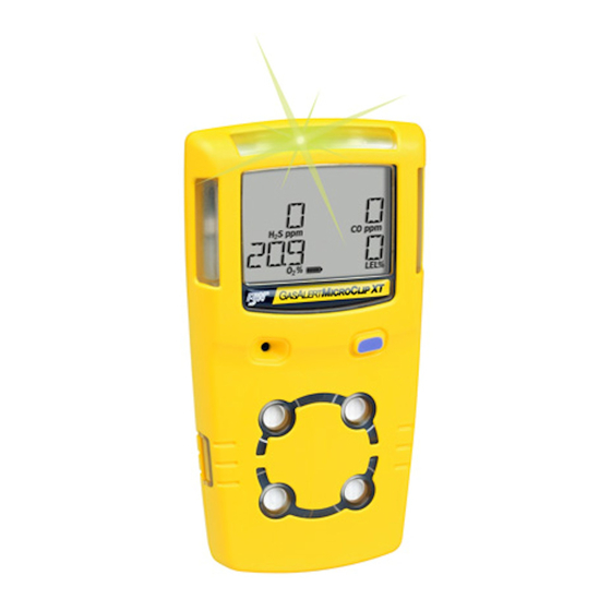
Page 11: Parts Of The Gasalertmicroclip
GasAlertMicroClip Parts of the GasAlertMicroClip Table 3. Parts of the GasAlertMicroClip Parts of the GasAlertMicroClip Item Description IntelliFlash Visual alarm indicators (LEDs) Alligator clip Charging connector / IR interface Pushbutton (C) Carbon monoxide (CO) sensor Hydrogen sulfide (H S) sensor Oxygen (O ) sensor Combustible (LEL) sensor... -
Page 12: Display Elements
GasAlertMicroClip Display Elements Table 4. Display Elements Display Elements Item Description Alarm condition Automatically zero sensor Numeric value Stealth mode Battery life indicator Gas identifier bars Gas cylinder Automatically span sensor Figure 2. Display Elements... -
Page 13: Pushbutton
GasAlertMicroClip Pushbutton Pushbutton Table 5. Pushbutton Pushbutton Description • To activate the detector press C. • To deactivate the detector, press and hold C until the OFF countdown is complete and the LCD deactivates. • To view the TWA, STEL, and peak (maximum) readings, press C twice. To clear the TWA, STEL, and peak readings, press C when the LCD displays RESET. -
Page 14: Activating The Detector
GasAlertMicroClip User Manual Activating the Detector Audible/Visual Test 1. All of the LCD elements display simultaneously as the detector a Caution beeps, flashes, vibrates, and activates the backlight. Only activate the detector in a fresh air environment and in a safe area. -
Page 15: Alarm Setpoints
GasAlertMicroClip Activating the Detector Alarm Setpoints Sensor and Power Test 4. Next, the TWA, STEL, low, and high alarm setpoints display. 5. The detector then tests the sensors. Note Alarm setpoints may vary by region. Refer to Factory Gas Alarm Setpoints. -
Page 16: Automatic Zero And O Calibration (Optional)
GasAlertMicroClip User Manual Automatic Zero and O Calibration (optional) Note If oxygen is configured to measure 20.8% vol., the oxygen 6. Auto-Zero on Startup: If enabled, the H S, CO, and LEL calibration screen displays 20.8% O sensors are automatically zeroed during startup. Each sensor is enabled individually. -
Page 17: Last Calibration Failed (Optional)
GasAlertMicroClip Activating the Detector Last Calibration Failed (optional) Note If any sensor failed the last calibration, CAL FAILURE displays If calibration is not performed, or is not pressed within on the screen. 2 minutes, the detector automatically deactivates. If the Force Calibration When Overdue is disabled, press acknowledge the warning. -
Page 18: Last Bump Test Failed
GasAlertMicroClip User Manual A bump test must be performed to enter normal operation. Apply Last Bump Test Failed gas to the sensors. Ensure the visual, audible, and vibrator If any sensor failed the last calibration, CAL FAILURE displays alarms activate. When the gas is removed, the detector briefly on the screen. -
Page 19: Self-Test Pass
GasAlertMicroClip Activating the Detector Self-Test Pass Battery Test When the detector has passed all startup self-tests, it enters normal The battery is tested when the detector is activated and continuously operation. The LCD displays the ambient gas readings. thereafter. See Specifications for Battery Runtimes. •... -
Page 20: Deactivating The Detector
To deactivate the detector, press and hold . The detector Fleet Manager II is required to configure the detector and sensors. And IR Link is also required. To purchase contact BW Technologies by • performs a sequence of two sirens with alternating flashes, Honeywell. - Page 21 GasAlertMicroClip Installing Fleet Manager II 6. When the Password dialog box displays, enter Admin (password is case sensitive). 7. Click OK. Fleet Manager II displays the Sensors tab that includes the 8. From the Devices toolbar, click Configure Device via IR Link. following sections: •...
-
Page 22: Using Fleet Manager Ii To Configure The Detector
GasAlertMicroClip User Manual 6. From the Sensors tab, click Retrieve from Device at the bottom Using Fleet Manager II to Configure the Detector of the window. The fields will populate with the detector’s current configurations. 7. Refer to the descriptions in the following sections to define settings and enable/disable options: •... -
Page 23: Detector Identification
GasAlertMicroClip Detector Identification Detector Identification Note The Detector Identification section provides information about the GasAlertMicroClip serial numbers use the KA serial number detector, current firmware revision, and hardware revision. Data can also prefix. be entered (25 characters per line) to display as a startup message on Hardware/Firmware Revision the detector LCD each time it is activated. -
Page 24: Sensor Configuration
GasAlertMicroClip User Manual Sensor Configuration Sensor Disabled Settings for the sensors are configured individually. Enter values or a Warning enable/disable options. Refer to Factory Gas Alarm Setpoints for Use extreme caution when disabling a sensor. The disabled setpoint values. sensor cannot detect and alarm against the applicable gas. Note 1. -
Page 25: Calibration Gas Concentration
GasAlertMicroClip Sensor Configuration 3. Click the Save to Device button located at the bottom of the Calibration Interval window. a Caution 4. The detector LCD automatically updates. The gas type and BW recommends that the sensors be calibrated once every sensor readings no longer display on the LCD for the applicable 180 days (6 months). -
Page 26: Low Alarm
GasAlertMicroClip User Manual The US OSHA method is defined as a moving average that accumulates Low Alarm over an 8-hour average. If the worker is in the field longer, the oldest Enter the low alarm setpoints for each sensor. Refer to Factory Gas accumulated values (first hour) are replaced by the newest values (ninth Alarm Setpoints for factory defined alarm setpoints. -
Page 27: Stel Interval
GasAlertMicroClip Sensor Configuration 2.Enter the setpoint for the CO and H S sensor in the STEL Alarm Auto-Calibration on Startup (Automatic O Calibration) field. Proceed to STEL Interval. When enabled, the O sensor is automatically calibrated during the STEL Interval startup self-tests. -
Page 28: User Options
GasAlertMicroClip User Manual display the peak concentration values until the alarm condition no longer User Options exists. The user options section provides detector features that can be enabled or disabled. The green checkmark indicates the option is enabled. Click The detector is shipped with Latching Alarms disabled. the checkbox to disable the option. -
Page 29: Stealth Mode
GasAlertMicroClip User Options Stealth Mode Low Alarm Acknowledge When enabled, the backlight, visual alarms, and audible alarms are When enabled, the audible alarm can be deactivated during a low alarm for the CO, H S, and LEL sensors. The LED and visual alarm indicators disabled. -
Page 30: Force Calibration When Overdue
GasAlertMicroClip User Manual Force Calibration When Overdue Cal Lock (Calibration IR Lock) When enabled, if a sensor(s) is past due, the sensor(s) must be When enabled, the sensors can only be calibrated using an infrared (IR) calibrated immediately, otherwise the detector deactivates. device to ensure calibrations are recorded. -
Page 31: Confidence Beep
For information and procedures, refer to Bump Test. confirmation that the detector is operating correctly. Note IntelliFlash is only applicable to GasAlertMicroClip XT, XL and IntelliFlash automatically deactivates during a low battery alarm, a self-test fail, a calibration fail, a bump test fail, or during an alarm event. -
Page 32: Datalog Interval
Click a language. When the settings are saved to the detector, the LCD displays warnings and notifications in the selected language. Note The detector is shipped with English as the default language. IntelliFlash and IntelliFlash Interval are only applicable to GasAlertMicroClip XT, XL and X3. -
Page 33: Alarms
GasAlertMicroClip Alarms alarm results. If Stealth is enabled, the audible and visual alarms are Alarms disabled, and only the vibrator alarm activates. Table 7. describes the detector alarms and corresponding screens. To change the factory-defined alarm setpoints, refer to Low Alarm, High During an alarm condition, the detector activates the backlight, audible/ visual/vibrator alarms, and displays the current ambient readings. - Page 34 GasAlertMicroClip User Manual Alarm Screen Alarm Screen Multi-Gas Alarm Over Limit (OL) Alarm • Sequence alternating low and high alarm • Fast siren and alternating flash siren and flash • L and gas bar flash • L and gas bars flash •...
-
Page 35: Computed Gas Exposures
GasAlertMicroClip Alarms Computed Gas Exposures Viewing Gas Exposures To view the TWA, STEL, and peak (maximum) readings, press twice. a Warning The LCD first displays the TWA gas exposures. To avoid possible personal injury, do not deactivate the detector during a work shift. TWA, STEL, and MAX readings reset once the detector is deactivated. -
Page 36: Clearing Gas Exposures
GasAlertMicroClip User Manual Clearing Gas Exposures Gas Alarm Setpoints Gas alarms are activated when detected gas concentrations are above a Caution or below the user-defined setpoints. Gas alarms are described below. Follow all safety procedures as defined by your employer. Confirm with your supervisor before clearing TWA and STEL Table 9. -
Page 37: Factory Gas Alarm Setpoints
GasAlertMicroClip Alarms Changing Alarm Setpoints Alarm Condition To change alarm setpoints, use the base station or IR Link and refer to the following under Sensor Configuration: Over Limit (OL) OL displays when readings are above or • Low Alarm below the sensor detection range. Refer to •... -
Page 38: Sensor Alarm
GasAlertMicroClip User Manual • If battery power becomes critically low, display. LOW BAT Sensor Alarm The detector performs a sequence of 10 rapid sirens with 1 second The detector tests for missing or defective sensors during the startup of silence in between (sequence reactivates seven times). The self-test and continuously thereafter. -
Page 39: Bump Test
GasAlertMicroClip Bump Test Bump Test... -
Page 40: Calibration
• Allow the detector to stabilize for 1 minute after activation before Calibration performing a calibration or bump test. Guidelines • If a certified calibration is required, contact BW Technologies by Honeywell. When calibrating the detector, adhere to the following guidelines: • Recommended gas mixture:... -
Page 41: Connecting The Gas Cylinder To The Detector
GasAlertMicroClip Calibration Connecting the Gas Cylinder to the Detector Table 11. Connecting the Gas Cylinder to the Detector Refer to the following Figure 7., Table 11., and procedures to connect the gas cylinder to the detector for calibration. Item Description Note Calibration cap Wind currents may cause false readings and poor calibrations. -
Page 42: Calibration Setup
GasAlertMicroClip User Manual Calibration Setup 6. Click . The fields populate with the detector’s current settings. The following calibration procedures are written as calibration 7. Refer to Calibration Gas Concentration for span gas values. performance is intended. If an error or failure occurs, refer to Calibration Troubleshooting. -
Page 43: Calibrating With The Ir Link
GasAlertMicroClip Calibration Table 12: Connecting to the IR Link Item Description Detector IR and charger interface IR Link Calibrating with the IR Link 2. The detector then reactivates and performs the CAL countdown. Continue holding until the CAL countdown is complete. a Caution Only calibrate in a fresh air environment and in a safe area. -
Page 44: Auto Zero And Oxygen Sensor Calibration
GasAlertMicroClip User Manual Auto Zero and Oxygen Sensor Calibration Auto Span 4. When auto zero is complete, APPLY GAS displays. Note Do not apply calibration gas until APPLY GAS displays, otherwise the auto zero function will fail. flashes while the detector zeroes the combustible and toxic sensors, and calibrates the oxygen sensor. -
Page 45: Calibration Due Date
GasAlertMicroClip Calibration When a sufficient amount of gas has been detected Calibration Due Date (approximately 30 seconds after the gas has been applied), the Note detector beeps once, flashes, and remains lit while the detector completes the span (approximately If a sensor fails calibration, the next due date for that sensor will 2 minutes). -
Page 46: Verification
GasAlertMicroClip User Manual Failed Sensor Past Calibration Due Date: If a sensor fails the span Verification and it is past the calibration due date, the following three screens 1. After calibration is complete and the detector returns to normal display. operation, verify the calibration using a gas cylinder other than the one used for calibration. -
Page 47: Datalogs
GasAlertMicroClip Datalogs Datalogs Event Logs The detector records various information that can be compiled to create The detector records the 10 most recent gas alarm events. The following a report. The detector is capable of storing 16 hours of information (when information is recorded: recording a datalog every 15 seconds). -
Page 48: Maintenance
GasAlertMicroClip User Manual • The battery can only be replaced by the manufacturer. Failure to Maintenance adhere to this caution can lead to fire and/or explosion. To maintain the detector in good operating condition, perform the • Warning: The GasAlertMicroClip uses a lithium battery that may following basic maintenance as required. -
Page 49: Charging The Battery
GasAlertMicroClip Maintenance Table 13. Connecting the Charging Adapter Charging the Battery To charge the battery, refer to Figure 8., Table 13., and the following procedures (1-8). Item Description Detector IR and charger interface Charging adapter Charging cable a Warning The detector must be charged in a safe area that is free of hazardous gas in temperatures of 32°F to 113°F (0°C to 45°C). -
Page 50: Replacing A Sensor Or Sensor Filter
GasAlertMicroClip User Manual 5. When charging is complete, the charging indicator stops flashing Replacing a Sensor or Sensor Filter and displays to indicate a full charge. Remove the charging a Warning adapter and activate the detector. To avoid personal injury, only use sensors that are If the battery indicator does not display, refer to Troubleshooting. -
Page 51: Removing The Back Shell
GasAlertMicroClip Maintenance Table 14. Replacing a Sensor or Sensor Filter Item Description Front shell Combustible (LEL) sensor PCB screws (2) Rear shell Machine screws (6) Sealing rib Carbon monoxide (CO) sensor Hydrogen sulfide (H S) sensor Oxygen (O ) sensor Sensor filter Figure 9. -
Page 52: Replacing The Sensor Filter
GasAlertMicroClip User Manual Figure 10. Liner Tab Replacing the Sensor Filter 1. Note the placement of the PCB to ensure it is replaced correctly. Remove the two screws on the PCB. Remove the PCB carefully. a Caution Ensure no damage occurs to the battery. 2. -
Page 53: Replacing The H S, Co, And Lel Sensor
GasAlertMicroClip User Manual Replacing the H S, CO, and LEL sensor 1. Note the placement of the PCB to ensure it is replaced correctly. Remove the two screws on the PCB. Remove the PCB carefully. a Caution Ensure no damage occurs to the battery. If the sensor filter is stuck to the sensors, remove and replace the sensor filter into the front shell. -
Page 54: Replacing The Oxygen Sensor Xt And Xl
GasAlertMicroClip Maintenance Replacing the Oxygen Sensor X3 Replacing the Oxygen Sensor XT and XL Note: Detectors that are configured for 1, 2, or 3 gases may Note: Detectors that are configured for 1, 2, or 3 gases may contain a dummy sensor in one of the four sensor locations. contain a dummy sensor in one of the four sensor locations. -
Page 55: Reassembling The Detector
GasAlertMicroClip User Manual XT Modell Reassembling the detector 1. To re-assemble the detector, perform the following: • Verify the PCB is seated correctly and inserted exactly as it was removed (sensors facing the front shell). • Replace the two PCB screws. •... - Page 56 GasAlertMicroClip Maintenance • Press the front and rear shells together firmly to ensure a proper seal. Ensure the front and rear shell have a uniform, tight 1/16 in (1 mm) seal on all sides of the detector. • When replacing the screws, they must be seated properly to prevent cross threading.
-
Page 57: Troubleshooting
GasAlertMicroClip User Manual Troubleshooting If a problem occurs, refer to the solutions in the Troubleshooting section. If the problem persists, contact BW Technologies by Honeywell Table 15. Troubleshooting Problem Possible Cause Solution Startup The detector does not activate. Depleted battery Charge battery. - Page 58 GasAlertMicroClip User Manual Table 15. Troubleshooting Problem Possible Cause Solution Detector Operation Detector does not display expected gas Sensor not stabilized Used sensor: wait 60 seconds readings after activation self-test. New sensor: wait 5 minutes (The oxygen sensor in the X3 needs 60 minutes to stabilize) Sensor(s) requires calibration Calibrate the sensor(s).
- Page 59 5 hours. This is normal. If the battery indicator does not light after charging for 8 hours, contact BW Technologies by Honeywell. When detector is activated after charging, Battery is defective Contact BW Technologies by Honeywell.
-
Page 60: Startup Troubleshooting
GasAlertMicroClip User Manual Startup Troubleshooting Error Screen Problem Solution Error Screen Problem Solution Sensor Error Calibrate the sensor(s). IR Lock Enabled Perform calibration using the Refer to Calibration. IR Link with Fleet Manager II The sensor failed If the IR Lock screen Reactivate the detector. -
Page 61: Calibration Troubleshooting
GasAlertMicroClip Calibration Troubleshooting Calibration Troubleshooting Error Screen Problem Solution Error Screen Problem Solution Auto-zero Attempt calibration again. No Gas Detected Ensure the sensor is enabled. Unsuccessful Refer to Calibration. If If the gas is not Verify gas cylinder is not ERROR displays again, S, CO, or LEL detected about 30... -
Page 62: Replacement Parts And Accessories
GasAlertMicroClip User Manual Replacement Parts and Accessories Model No. Description a Warning MC2-SS Replacement quad sensor screens (Kit To avoid personal injury and/or damage to the detector, use only the specified replacement parts. of 2). To order parts or accessories listed in the following table, contact BW MC2-SS-K1 Replacement quad sensor screens (Kit Technologies by Honeywell. - Page 63 GasAlertMicroClip Replacement Parts and Accessories Model No. Description Model No. Description CG2-M-200-103 Single gas cylinder: CO (100 ppm), DOCK2-0-1P-00-G GasAlertMicroClip XT/XL docking bal N (103 l) module Datalogging Accessories CG-BUMP1 Bump alarm gas aerosol: CH (2.5%), (10%), H S (40 ppm), CO (200...
- Page 64 GasAlertMicroClip User Manual Model No. Description Model No. Description MCX3-FC1B Replacement front enclosure - Black MCXL-MPCB1 Replacement main PCB and battery (Compatible with X3 only) (compatible with XL only) MC2-MCPCB1 MC-LCD-K1 Replacement LCD (for XT) MCX3-BC1 Replacement back enclosure - Yellow MC-SCREW-K1 Replacement screw kit (for XT) (Compatible with X3 only)
-
Page 65: Specifications
GasAlertMicroClip Specifications Self-test: Initiated upon activation Specifications Calibration: Automatic zero and automatic span Instrument dimensions: XT: 11.25 x 6.00 x 2.89 cm (4.4 x 2.4 x 1.1 in.) Oxygen sensor: Automatic span upon activation (enable/disable) XL-X3: 11.25 x 6.00 x 3.22 cm (4.4 x 2.4 x 1.2 in.) User field options: Startup message, Confidence Beep, latching Weight: alarms, enable/disable safe display mode, oxygen measurement,... - Page 66 ATEX CE 0539 II 1 G Ex da ia IIC T4 Ga Approved battery: Sira 13ATEX2330 Approved batteries for GasAlertMicroClip XT: EN 60079-0, EN 60079-11, EN 60079-26 Narada NL 503759 IECEx Ex da ia IIC T4 Ga IECEx CSA 05.0015...
-
Page 67: General Datalogger Specifications
GasAlertMicroClip Specifications ICES-003 Canadian EMI requirements. These limits are designed to General Datalogger Specifications provide reasonable protection against harmful interference in a Storage: 16 hours at 15-second intervals residential installation. This equipment generates, uses and can radiate Memory type: Wraparound memory ensures most recent data is always radio frequency energy and, if not installed and used in accordance with the instructions, may cause harmful interference to radio saved... - Page 68 50120681-002 EN-F2 English © BW Technologies 2017. All rights reserved.
Need help?
Do you have a question about the GasAlertMicroClip XT and is the answer not in the manual?
Questions and answers