Table of Contents
Advertisement
Quick Links
Advertisement
Table of Contents

Related Manuals for BW Technologies GasAlertMax XT II


Summary of Contents for BW Technologies GasAlertMax XT II
- Page 1 1, 2, 3, and 4-Gas Detector Technical Reference Guide...
-
Page 2: Table Of Contents
Introduction ..................................1 Gases Monitored ................................2 Safety Information - Read First............................2 Getting Started ..................................6 Parts of the GasAlertMax XT II............................7 Display Elements ................................8 Activating/Deactivating the Detector ..........................10 Startup Tests ..................................10 Battery Test ................................... 10 Audible/Visual Test ................................ -
Page 3: Title Page
GasAlertMax XT II Technical Reference Guide Title Page Bump Test..................................17 Force Bump Enabled (optional) ............................. 18 Startup Test Pass ................................18 Startup Test Fail................................19 Installing Fleet Manager II ..............................20 Using Fleet Manager II to Configure the Detector ......................20 Device Configuration ................................ - Page 4 GasAlertMax XT II Technical Reference Guide Title Page Calibration Interval ................................. 28 Bump Interval ................................. 28 Low Alarm ..................................28 High Alarm ..................................28 TWA Alarm..................................29 STEL Alarm..................................29 STEL Interval ................................. 30 TWA Period (hours) ............................... 30 Correction Factor (%)..............................30 50% LEL = (%CH4)................................
- Page 5 GasAlertMax XT II Technical Reference Guide Title Page Calibration ..................................40 Guidelines ..................................40 Diagnostics Protection ..............................41 Connecting the Gas Cylinder to the Detector ........................ 41 Calibration Procedure ..............................42 Auto Zero Sensor..............................43 Auto Span ................................. 44 Calibration Due Date ..............................45 Verification ................................
- Page 6 GasAlertMax XT II Technical Reference Guide Title Page General Datalogger Specifications ..........................67...
- Page 7 List of Figures Figure Title Page Parts of the GasAlertMax XT II..........................7 Display Elements..............................8 Connecting the IR Link ............................20 Device Configuration Section ..........................21 Sensor Configuration Tab (H S) ........................26 Connecting the Gas Cylinder to the Detector ..................... 42 Calibrate Device Dialog Box..........................
- Page 8 List of Tables Table Title Page Gases Monitored ..............................2 International Symbols ............................5 Parts of the GasAlertMax XT II..........................7 Display Elements..............................8 Pushbutton ................................9 Connecting the IR Link ............................20 Alarms ................................32 Computed Gas Exposures ..........................35 Gas Alarm Setpoints ............................
-
Page 9: Contacting Bw Technologies By Honeywell
To ensure personal safety, read Safety Information - Read First and aCautions before using the detector. The GasAlertMax XT II gas detector (“the detector”) warns of hazardous gas at levels above user-defined alarm setpoints. The detector is a personal safety device. It is your respons bility... -
Page 10: Gases Monitored
GasAlertMax XT II Technical Reference Guide Safety Information - Read First Gases Monitored Use the detector only as specified in this technical reference guide, The following table lists the gases that are monitored by the detector. otherwise the protection provided by the detector may be impaired. - Page 11 • Do not use the detector if it is damaged. Inspect the detector before using. Look for cracks and/or missing parts. • Use only sensor(s) that are specifically designed for the GasAlertMax XT II model. Refer to Replacement Parts and Accessories •...
- Page 12 212°F (100°C), or incinerate. • Do not use any other lithium batteries with the GasAlertMax XT II detector. Use of any other cell can cause fire and/or explosion. To order and replace the MX-BAT01 battery, refer to...
- Page 13 GasAlertMax XT II Safety Information - Read First aCautions • Warning: Lithium polymer cells exposed to heat at 266°F (130°C) for 10 minutes can cause fire and/or explosion. • Dispose of used lithium cells immediately. Do not disassemble and do not dispose of in fire. Do not mix with the solid waste stream.
-
Page 14: Getting Started
GasAlertMax XT II Technical Reference Guide Getting Started The detector is shipped with the sensors, pump, and rechargeable battery installed. To replace sensors, the pump, or the battery, refer to The list below provides the standard items included with the detector. -
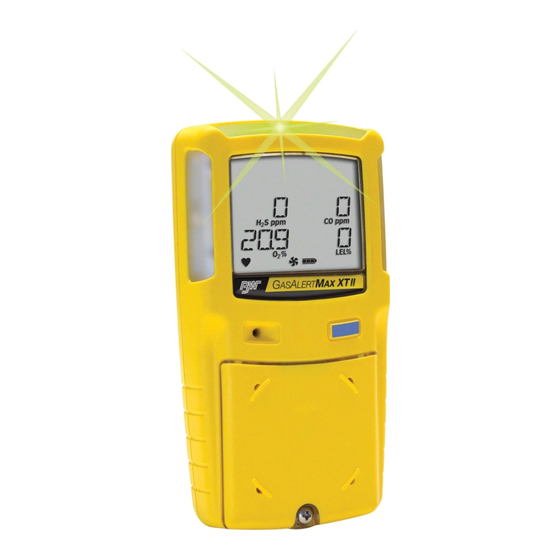
Page 15: Parts Of The Gasalertmax Xt Ii
GasAlertMax XT II Parts of the GasAlertMax XT II Parts of the GasAlertMax XT II Table 3. Parts of the GasAlertMax XT II Item Description Visual alarm indicators (LEDs) Pump quick connector Pump filter and moisture filter Pushbutton Alligator clip... -
Page 16: Display Elements
GasAlertMax XT II Technical Reference Guide Display Elements Table 4. Display Elements Item Description Alarm condition Automatically zero sensor indicator Numeric values Battery life indicator Pump indicator Heartbeat indicator Gas type identifiers Gas cylinder indicator Automatically span sensor indicator Figure 2. Display Elements... - Page 17 GasAlertMax XT II Display Elements Table 5. Pushbutton Pushbutton Description • To activate the detector press C. • To deactivate the detector, press and hold C until the OFF countdown is complete and the LCD deactivates. • To view the date/time, TWA, STEL, and maximum (MAX) readings, press C twice rapidly. To clear the TWA, STEL, and MAX readings, press C when the LCD displays CLEAR ALL.
-
Page 18: Activating/Deactivating The Detector
GasAlertMax XT II Technical Reference Guide Activating/Deactivating the Detector Battery Test Note The detector performs a battery test during startup. If the battery has insufficient power to operate, the following screens displays before Ensure the diffusion cover is attached prior to activating the deactivating. -
Page 19: Firmware Version
GasAlertMax XT II Startup Tests Firmware Version Location Logging 2. The current firmware version installed on the detector 4. If the Location Logging option is enabled, the detector displays on the LCD. prompts for a number (1-999) to be entered that identifies the location (wells, plants, or other areas) where the detector is being used. -
Page 20: Pump Test On Startup
GasAlertMax XT II Technical Reference Guide Pump Test on Startup Using your finger, block the end of the hose. The follow- ing screen displays. Note The diffusion cover must be attached to the detector to activate the pump and initiate the pump test. -
Page 21: Alarm Setpoints
GasAlertMax XT II Startup Tests Unsuccessful Block Pump Test: If the pump is not When the diffusion cover is replaced, the detector operating correctly, the following screens display before activates the pump alarm. the detector deactivates. HIGH displays, and L and J flashes. Press C to Activate the detector again. -
Page 22: Self-Test
GasAlertMax XT II Technical Reference Guide Next, the LOW and HIGH alarm setpoints display for all Unsuccessful Self-Test of the enabled sensors. Lockout on Self-Test Error Option Enabled: If this option is enabled and a sensor fails, the following screens display before the detector deactivates. -
Page 23: Automatic Zero For H S, Co, O , And Lel
Only activate the detector in a safe area that is free of hazardous gas to ensure an accurate auto zero. 8. To initiate auto zero during startup, the Auto Zero on Startup option must be enabled (sensors are enabled Note individually). BW Technologies by Honeywell recommends the sensor(s) be calibrated immediately. -
Page 24: Calibration Due Date (Optional)
GasAlertMax XT II Technical Reference Guide Calibration Due Date (optional) Force Calibration Enabled (optional) 9. The LCD displays the number of days remaining until the 10. If the Force Calibration option is enabled in Fleet next calibration is due. Manager II and a sensor is past due, the sensor(s) must be calibrated to continue and enter normal operation. -
Page 25: Cal Ir Lock Enabled (Optional)
Options. Bump Test Note BW Technologies by Honeywell recommends to bump test the sensors before each day’s use to confirm their ability to respond to gas by exposing the detector to a gas concentration that exceeds the alarm setpoints. -
Page 26: Force Bump Enabled (Optional)
GasAlertMax XT II Technical Reference Guide 12. The LCD next displays the number of days remaining If Force Bump is disabled, press C to acknowledge the until the next bump test is due. warning and continue with the startup tests. -
Page 27: Startup Test Fail
GasAlertMax XT II Startup Tests Startup Test Fail After the detector enters normal operation, ERR displays if a sensor has failed the self-test. To determine the cause and solutions for a failed sensor, refer to Troubleshooting. -
Page 28: Installing Fleet Manager Ii
GasAlertMax XT II Technical Reference Guide Installing Fleet Manager II Fleet Manager II is required to configure the detector. To install Fleet Manager II, refer to the Fleet Manager II CD-ROM that includes the • installation wizard, and • Fleet Manager II Operator’s Manual. -
Page 29: Device Configuration
GasAlertMax XT II Device Configuration Device Configuration 8. From the Devices too bar, click Configure Device via IR Link to access the GasAlertMax XT Configuration The Device Configuration section displays data about the detector, window. allows for a startup message to be entered, and is used to enable/dis- 9. -
Page 30: Serial Number Field
GasAlertMax XT II Technical Reference Guide Startup Message Bottom Line Refer to the following options for descriptions and functionality. Enter a line of text that will display on the detector LCD during startup Note (maximum 25 characters, spaces included). Enter any type of informa- The Serial Number, Firmware Version, and Hardware tion such as employee name, plant, area, emergency number(s), etc. -
Page 31: Safe Mode
GasAlertMax XT II Device Configuration Safe Mode display the high peak concentration until the alarm condition no longer exists. If enabled, SAFE displays continuously on the LCD unless an alarm The detector is shipped with the Latching Alarms option disabled. -
Page 32: Force Bump
GasAlertMax XT II Technical Reference Guide Force Bump Cal IR Lock A bump test must be performed regularly to ensure the sensor(s) are If enabled, the sensor(s) can only be calibrated using the IR Link with responding correctly to test gas. If enabled and the sensor(s) is past due, Fleet Manager II or the MicroDock II station. -
Page 33: Location Logging
GasAlertMax XT II Device Configuration Location Logging Force Block Test The Location Logging logs where the detector is being used such as a The force block test verifies the pump is operating correctly by compar- gas plant, well site, vehicle, etc. -
Page 34: Confidence Interval
GasAlertMax XT II Technical Reference Guide Sensor Configuration Confidence Interval The Sensor Configuration tab adjusts settings for each individual The Confidence Interval (seconds) field defines how often the sensor. A separate sensor tab is provided for each sensor. Figure 5. -
Page 35: Sensor Disabled
GasAlertMax XT II Sensor Configuration Sensor Disabled 5. The LCD automatically updates. In the following exam- ple, the CO gas type and sensor readings no longer a Warning displays. Use extreme caution when disabling a sensor. The disabled sensor cannot detect and alarm against the applicable gas. -
Page 36: Calibration Interval
GasAlertMax XT II Technical Reference Guide Calibration Interval setpoints. Verify that the audible and visual alarms activate. Calibrate if the readings are not within the specified limits. Define how often a sensor must be calibrated in the Calibration Interval (days) field. A different cal bration interval can be set for each sensor. -
Page 37: Twa Alarm
GasAlertMax XT II Sensor Configuration TWA Alarm STEL Alarm The time-weighted average (TWA) is a safety measure used to The short term exposure limit (STEL) is the maximum permissible gas determine accumulated averages of gases. An average is determined concentration a worker can be safely exposed to for short periods of time using the Occupational Safety and Health Administration (OSHA) (5-15 minutes maximum). -
Page 38: Stel Interval
GasAlertMax XT II Technical Reference Guide STEL Interval Note Regulations vary depending upon region. Adhere to the regula- The STEL Interval option provides protection for workers from over tions defined for your area. exposure to high concentrations of gas, and is based on user-defined 5-15 minute intervals. -
Page 39: 50% Lel = (%Ch4)
GasAlertMax XT II Sensor Configuration 50% LEL = (%CH4) 10% (of reading) Over-span If the LEL By Volume CH4 option is enabled, a percentage value can be When enabled, the detector automatically over-spans the LEL sensor by entered in the 50% LEL = (%CH4) field to display the LEL reading in 10% of the span concentration to ensure the span meets CSA stan- %vol. -
Page 40: Alarms
GasAlertMax XT II Technical Reference Guide Alarms Table 7 describes the detector alarms and corresponding screens. During an alarm condition, the detector activates the backlight, audible/visual/ vibrator alarms, and displays the current ambient gas reading. If more than one type or level of alarm exists simultaneously, a multi-gas alarm results. - Page 41 GasAlertMax XT II Alarms Table 7. Alarms Alarm Screen Alarm Screen Multi-Gas Alarm Sensor Alarm • Alternating low and high alarm siren and flash • ERR displays • L and target gas bar flash • Vibrator alarm activates Over Limit (OL) Alarm Low Battery Alarm •...
- Page 42 GasAlertMax XT II Technical Reference Guide Table 7. Alarms Alarm Screen Alarm Screen Automatic Deactivation Alarm Confidence Beep • Sequence of 10 rapid sirens and alternating • One beep every 1-120 seconds (user-defined) flashes with 1 second of silence in between...
-
Page 43: Computed Gas Exposures
GasAlertMax XT II Computed Gas Exposures Computed Gas Exposures Viewing and Clearing Gas Exposures a Warning To view the TWA, STEL, and maximum (MAX) readings, press C twice rapidly. The LCD first displays the current time and date. To prevent possible personal injury, do not deactivate the detector during a work shift. -
Page 44: Gas Alarm Setpoints
GasAlertMax XT II Technical Reference Guide Gas Alarm Setpoints Next, the MAX readings display. The alarm setpoints trigger the gas alarms and are described Table 9. Table 9. Gas Alarm Setpoints Alarm Condition Toxics and combustibles: Ambient Last, the CLEAR ALL readings screen displays. -
Page 45: Resetting Gas Alarm Setpoints
GasAlertMax XT II Computed Gas Exposures Resetting Gas Alarm Setpoints Stopping a Gas Alarm Table 10. lists alarm setpoints as defined by Occupational Safety and The low and high alarms stop when the ambient gas concentrations Health Association (OSHA). returns to a concentration below the low alarm setpoint. -
Page 46: Pump Alarm
GasAlertMax XT II Technical Reference Guide Pump Alarm Low Battery Alarm The pump draws air over the sensors continually. If the pump stops The detector tests the battery on activation and continuously thereafter. operating or becomes blocked, the detector activates the pump alarm. -
Page 47: Bump Test
GasAlertMax XT II Bump Test Bump Test 4. The detector should enter alarm. Verify the audible and visual alarms activate, and that the LCD readings match A bump test is the process of applying a small amount of test gas to the span gas concentrations of the gas cylinder being force the detector into alarm. -
Page 48: Calibration
GasAlertMax XT II Technical Reference Guide Calibration • If a certified calibration is required, contact BW Technologies by Honeywell. Guidelines • Cal bration can be performed using either a 0.5 l/min regulator or a demand flow regulator. Recommended gas mixture: •... -
Page 49: Diagnostics Protection
GasAlertMax XT II Calibration Diagnostics Protection Connecting the Gas Cylinder to the Detector The detector tests the ambient air (auto-zero) and the test gas that is Refer to the following procedures and Figure 6. to connect the gas applied (auto span) to ensure it meets expected values. Auto-zero sets cylinder to the detector for calibration. -
Page 50: Calibration Procedure
GasAlertMax XT II Technical Reference Guide Calibration Procedure 5. When calibration is complete, disconnect the hose from the detector and the regulator. a Caution 6. Ensure the gas cylinder is stored according to the Calibrate only in a safe area that is free of hazardous manufacturer’s specifications. -
Page 51: Auto Zero Sensor
GasAlertMax XT II Calibration 4. Press and hold C while the detector performs the OFF flashes while the detector automatically zeroes countdown. Continue to hold C as the detector briefly the combustible and toxic sensors, and calibrates the deactivates. oxygen sensor. -
Page 52: Auto Span
GasAlertMax XT II Technical Reference Guide Auto Span Unsuccessful Span If the sensor(s) fails the span, the following screen displays. When auto zero is complete, APPLY GAS and display, and flashes. Refer to the following for possible causes and solutions. -
Page 53: Calibration Due Date
GasAlertMax XT II Calibration Calibration Due Date If a sensor(s) fails any step of the cal bration, the following screen displays. If a sensor(s) does not successfully span, the calibration due date for that sensor(s) will not reset. Note If calibration is unsuccessful for a sensor(s), the calibration due... -
Page 54: Verification
GasAlertMax XT II Technical Reference Guide After the span is complete, the following calibration due date screens If a sensor fails to span successfully and it is past the calibration due display before returning to normal operation. date, the following screens display. -
Page 55: Calibrating Using The Ir Link
GasAlertMax XT II Calibration 3. To ensure the readings are accurate, apply the verifica- To calibrate using the IR Link, complete the following: tion gas for the same amount of time as was applied to 1. From the PC, open Fleet Manager II. - Page 56 GasAlertMax XT II Technical Reference Guide 7. Enter the span gas concentration values. The values entered in the Calibrate Device popup must match the span concentration values on the gas cylinder. 8. Click inside the checkbox for each sensor that will be calibrated, and then click Calibrate.
-
Page 57: Event Logs
GasAlertMax XT II Event Logs Event Logs The following information is recorded in a datalog: • Serial number of the detector The detector records the thirty most recent gas alarm events. Information that is recorded from an event is as follows: •... -
Page 58: Bump And Calibration Results
GasAlertMax XT II Technical Reference Guide Bump and Calibration Results • Audible and visual indicator status • Sensor type and sensor status The detector records the bump test and calibration results. The results can then be imported into Fleet Manager II to create detailed reports. -
Page 59: Maintenance
Refer to Charging the Battery. • Charge the battery using the GasAlertMax XT II or the GasAlertMicroClip charger adapter only. Do not use any other charger adapters. Failure to adhere to this precaution can lead to fire and/or explosion. -
Page 60: Charging The Battery
GasAlertMax XT II Technical Reference Guide Charging the Battery Table 11. Connecting the Charger Adapter Item Description IR and charger interface GasAlertMax XT II Charger adapter Charger cable a Warning The detector must be charged in a safe area that is free of hazardous gas in temperatures of 32°F to 113°F... -
Page 61: Optimum Battery Operation
GasAlertMax XT II Maintenance Replacing the Battery 4. Allow the battery to charge for 6 hours. The charging indicator flashes (low, mid, and full charge repeatedly) on To replace the lithium battery, refer to Replacement Parts and Accesso- the LCD while the battery is charging. - Page 62 GasAlertMax XT II Technical Reference Guide Table 12. Replacing a Sensor or Sensor Filter Item Description Front shell LEL sensor PCB screws (2) Pump Rear shell Machine screws (6) Pump inlet Pump filter (particulate) Moisture filter CO sensor S sensor...
- Page 63 GasAlertMax XT II Maintenance Figure 9. Replacing a Sensor or Sensor Filter...
- Page 64 GasAlertMax XT II Technical Reference Guide 1. Deactivate the detector. 5. Remove the two PCB screws. 2. Remove the pump inlet screw and the pump inlet. Refer 6. Lift the PCB upward and tilt to the left. Lay the PCB Figure 13.
-
Page 65: Replacing The Pump Filters
GasAlertMax XT II Maintenance Replacing the Pump Filters Note When inserting a new sensor filter, ensure the white side is Filters are inserted into the pump inlet to prevent dust particulates and facing the sensors and the black side is facing the front shell. - Page 66 GasAlertMax XT II Technical Reference Guide 1. Remove the one machine screw from the pump inlet and gently lift the bottom of the inlet outward at a 45° angle. Figure 13. Removing the Pump Filters 2. Gently lift the pump inlet upwards to remove. Ensure the Figure 12.
-
Page 67: Replacing The Pump
GasAlertMax XT II Maintenance 3. Depending upon the circumstance, replace either just the particulate filter or both. Refer to Particulate Filters Moisture Filters. 4. Reattach the pump inlet and replace the screw. Tighten the screw using 3-4 in-lbs. torque. Do not overtighten. -
Page 68: Troubleshooting
GasAlertMax XT II Technical Reference Guide Troubleshooting If a problem occurs, refer to the solutions provided in Table 15. If the problem persists, contact BW Technologies by Honeywell. Figure 14. Troubleshooting Problem Possible Cause Solution The detector does not activate. - Page 69 GasAlertMax XT II Troubleshooting Table 7. Troubleshooting Problem Possible Cause Solution Detector does not display normal Sensors not stabilized Used sensor: Wait 60 seconds ambient gas reading after startup tests. New sensor: Wait 5 minutes Sensor(s) requires calibration Calibrate the sensor(s). Refer to Calibration.
- Page 70 GasAlertMax XT II Technical Reference Guide Table 7. Troubleshooting Problem Possible Cause Solution Detector intermittently enters alarm Ambient gas levels are near alarm Detector is operating normally. Use caution in without reason. setpoint or the sensor is exposed to a suspect areas.
-
Page 71: Replacement Parts And Accessories
Quad calibration kit with regulator, quad gas Model No. Description CK-Q58-4 cylinder (CG-Q58-4), hose, and carrying case SR-W- Combustible (LEL) sensor XT-SS-1 Sensor filter for GasAlertMax XT II, Kit of 2 MC75C GA-PFMAX Particulate filters (kit of 5) Oxygen (O ) sensor SR-X10-C1 GA-PFMAX-... - Page 72 GasAlertMax XT II Technical Reference Guide Model No. Description XT-SCREW- Replacement screw kit (40 screws and screw- driver) XT-BAT-K1 Battery replacement kit XT-RPUMP- Pump replacement kit GA-HXT GasAlertMax XT carrying holster GA-BXT GasAlertMax XT rubber boot XT-AG-1 Alligator clip (stainless steel) *Add suffix (-UK) for United Kingdom mains plug, (-EU) for European mains plug, (-AU) for Australian mains plug.
-
Page 73: Specifications
GasAlertMax XT II Specifications Specifications Visual alarm: Red light-emitting diodes (LEDs) Display: Alphanumeric liquid crystal display (LCD) Instrument dimensions: 13.1 x 7.0 x 5.2 cm (5.1 x 2.8 x 2.0 in.) Backlight: Activates upon startup and when the pushbutton is pressed;... - Page 74 GasAlertMax XT II Technical Reference Guide Approved battery for GasAlertMax XT II product: This equipment has been tested and found to comply with the limits Lithium-ion polymer (MA-BAT01) as per standards EN50020, UL913, for a Class B digital device, pursuant to Part 15 of the FCC Rules and CSA C22.2 No.
- Page 75 GasAlertMax XT II Specifications General Datalogger Specifications Storage: 375 hours at 15-second intervals (75% redundancy) Memory type: Wraparound memory ensures most recent data is always saved Sample rate: One reading every 1-120 seconds Data recorded: All sensor readings, all alarm conditions, cal brations,...
Need help?
Do you have a question about the GasAlertMax XT II and is the answer not in the manual?
Questions and answers