Table of Contents
Advertisement
Advertisement
Table of Contents

Subscribe to Our Youtube Channel
Related Manuals for BW Technologies Max XT II


Summary of Contents for BW Technologies Max XT II
- Page 1 1, 2, 3, and 4-Gas Detector Operator’s Manual...
-
Page 2: Limited Warranty And Limitation Liability
Limited Warranty and Limitation Liability BW Technologies LP (BW) warrants the product to be free from defects in material and workmanship under normal use and service for a period of two years, beginning on the date of shipment to the buyer. This warranty extends only to the sale of new and unused products to the original buyer. -
Page 3: Zeroing The Sensors
GasAlertMax XT II Introduction Safety Information - Read First The operator’s manual provides basic information to operate Use the detector only as specified in this operator’s manual and the GasAlertMax XT II gas detector. For complete operating the technical reference guide, otherwise the protection provided instructions, refer to the GasAlertMax XT II Technical Reference by the detector may be impaired. - Page 4 GasAlertMax XT II detector. Use of any other cell can cause with a known concentration of calibration gas after any fire and/or explosion. To order and replace the MX-BAT01 exposure to contaminants/poisons such as sulfur lithium battery, contact BW Technologies by Honeywell. compounds, silicon vapors, halogenated compounds, etc. Warning: •...
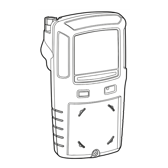
- Page 5 GasAlertMax XT II Parts of the GasAlertMax XT II Parts of the GasAlertMax XT II Item Description Visual alarm indicators (LEDs) Pump quick connector Pump filter and moisture filter Pushbutton Alligator clip Charging connector and IR interface Diffusion cover locking screw (1) Diffusion cover Audible alarm Liquid crystal display (LCD)
-
Page 6: Display Elements
GasAlertMax XT II Operator’s Manual Display Elements Item Description Alarm condition Automatically zero sensor Numeric values Battery life indicator Pump indicator Heartbeat indicator Gas type identifiers Gas cylinder Automatically span sensor... -
Page 7: Push Button
GasAlertMax XT II Pushbutton Pushbutton Pushbutton Description • To activate the detector, press C. • To deactivate the detector, press and hold C until the OFF countdown is complete. • To view the date/time, TWA, STEL, and maximum (MAX) readings, press C twice rapidly. To clear the TWA, STEL, and MAX readings, press C when the LCD displays CLEAR ALL. -
Page 8: Calibration And Bump Test Installation
GasAlertMax XT II Operator’s Manual Calibration and Bump Test Installation... - Page 9 GasAlertMax XT II Calibration Calibration Caution 4. Refer to Calibration and Bump Test Installation (page 6). Attach the Calibrate only in a safe area that is free of hazardous gas 0.5 l/min. regulator or the demand in an atmosphere of 20.9 % oxygen. Do not calibrate the flow regulator and apply gas.
- Page 10 GasAlertMax XT II Operator’s Manual Alarms Refer to the following table for information about alarms and corresponding screens. Alarm Screen Alarm Screen Low Alarm TWA Alarm • Slow siren • Fast siren • Slow alternating flash • Fast alternating flash •...
- Page 11 GasAlertMax XT II Alarms Alarm Screen Alarm Screen Sensor Alarm Automatic Deactivation Alarm • ERR displays • Sequence of 10 rapid sirens and alter- nating flashes with 1 second of silence in between (reactivates seven times) • L flashes and the vibrator alarm activates •...
-
Page 12: Options Menu
GasAlertMax XT II Operator’s Manual Options Menu spanned using the IR Link or MicroDock II station with Fleet Manager II. The detector, IR Link adapter, and Fleet Manager II software Force Bump: • If enabled, a bump test must be performed to are required to define options. -
Page 13: Maintenance
GasAlertMax XT II Maintenance TWA Alarm (ppm): • Define the time-weighted average (TWA) by pressing . The vibrator, alarm LEDs, and LCD alarm setpoint (toxic sensors only). remain operational (toxic and LEL only). STEL Alarm (ppm): • Define the short-term exposure limit Maintenance (STEL) alarm setpoint (toxic sensors only). - Page 14 GasAlertMax XT II Operator’s Manual To reach full battery capacity, allow a new battery to Replacing a Sensor or Sensor Filter fully charge and discharge three times. Warning To avoid personal injury and/or property damage, only use sensors that are specifically designed for the detector.
- Page 15 GasAlertMax XT II Maintenance...
- Page 16 GasAlertMax XT II Operator’s Manual Because the pump hose is connected to the rear shell and front shell pump, carefully remove the rear Item Description shell by lifting upward and tilting to the left. Both the rear and front shell are laying flat side by side. Front shell LEL sensor PCB screws (2)
-
Page 17: Specifications
GasAlertMax XT II Specifications Slide the LEL, CO, and H S sensor(s) outward to 13. Activate the detector and then calibrate the new sensor(s). Refer to Calibration. remove. Specifications To remove the oxygen sensor, gently insert a screw- driver to the back of the oxygen sensor to push out Instrument dimensions: 13.1 x 7.0 x 5.2 cm the sensor. - Page 18 GasAlertMax XT II Operator’s Manual Alarm conditions: TWA alarm, STEL alarm, low alarm, high ber after the second letter determines the year of manufacture. alarm, multi-gas alarm, over limit (OL) alarm, low battery alarm, E.g., MA 110-000001 = 2010 year of manufacture confidence beep, automatic deactivation alarm, and pump Approved batteries: alarm...
- Page 19 GasAlertMax XT II Specifications FCC Rules and ICES-003 Canadian EMI requirements. These limits are designed to provide reasonable protection against harmful interference in a residential installation. This equipment generates, uses and can radiate radio frequency energy and, if not installed and used in accordance with the instructions, may cause harmful interference to radio communications.
- Page 20 GasAlertMax XT II Operator’s Manual...
- Page 21 GasAlertMax XT II Specifications...
- Page 22 GasAlertMax XT II Operator’s Manual...
- Page 23 129535 D6558/0 [English] © BW Technologies 2010. All rights reserved.
Need help?
Do you have a question about the Max XT II and is the answer not in the manual?
Questions and answers