BW Technologies MicroClip XT Technical Reference Manual
1, 2, 3, and 4-gas detector
Hide thumbs
Also See for MicroClip XT:
- Quick reference manual (29 pages) ,
- Operator's manual (27 pages)
Table of Contents
Advertisement
Advertisement
Table of Contents
Troubleshooting

Related Manuals for BW Technologies MicroClip XT


Summary of Contents for BW Technologies MicroClip XT
- Page 1 1, 2, 3, and 4-Gas Detector Technical Reference Guide...
-
Page 2: Table Of Contents
Table of Contents Heading Page Introduction ..................................1 Zeroing the Sensors ................................1 Contacting BW Technologies by Honeywell ........................2 Safety Information - Read First............................2 a Cautions ..................................3 Sensor Poisons and Contaminants ..........................6 Getting Started ..................................7 Parts of the GasAlertMicroClip XT ............................ - Page 3 GasAlertMicroClip XT Technical Reference Guide Title Page Last Calibration Failed (optional) ..........................14 Overdue Calibration ..............................14 Cal IR Lock ................................14 Bump Test ................................14 Last Bump Test Failed .............................. 15 Force Bump (optional) .............................. 15 Self-Test Pass................................16 Self-Test Fail ..................................
- Page 4 GasAlertMicroClip XT Technical Reference Guide Title Page Auto Zero on Startup..............................25 O2 Auto-Calibration on Startup (Automatic O Calibration) ................... 26 LEL By Vol CH4 ................................26 User Options..................................26 Cal Lock (Calibration IR Lock) ............................27 The detector is shipped with disabled.
- Page 5 GasAlertMicroClip XT Technical Reference Guide Title Page Automatic Deactivation Alarm ............................36 Bump Test..................................37 Calibration ..................................38 Guidelines ..................................38 Diagnostics Test ................................38 Connecting the Gas Cylinder to the Detector ........................ 39 Calibration Setup ................................40 Setting Span Gas Concentration Values ........................40 Calibrating with the IR Link ............................
- Page 6 GasAlertMicroClip XT Technical Reference Guide Title Page Startup Troubleshooting ..............................56 Calibration Troubleshooting ............................57 Replacement Parts and Accessories ..........................58 Specifications ..................................60 General Datalogger Specifications ..........................61...
- Page 7 GasAlertMicroClip XT Technical Reference Guide Title Page...
-
Page 8: List Of Figures
List of Figures Figure Title Page Parts of the GasAlertMicroClip XT......................... 8 Display Elements..............................9 Connecting the IR Link ............................20 Detector Identification............................21 CO Sensor Configuration ............................ 22 Disabled Sensor ..............................22 Fleet Manager II IR Link User Options ........................ 26 Connecting the Gas Cylinder to the Detector ...................... - Page 9 GasAlertMicroClip XT Technical Reference Guide viii...
- Page 10 List of Tables Table Title Page Gases Monitored ..............................1 International Symbols ............................5 Parts of the GasAlertMicroClip XT......................... 8 Display Elements..............................9 Pushbutton ................................10 Connecting the IR Link ............................19 Alarms ................................. 31 Computed Gas Exposures ..........................33 Gas Alarm Setpoints ............................
- Page 11 GasAlertMicroClip XT Technical Reference Guide...
-
Page 12: Introduction
GasAlertMicroClip XT Introduction Table 1. Gases Monitored a Warning Gas Detected Unit of Measure To ensure personal safety, read Safety Information - Read Hydrogen sulfide (H parts per million (ppm) First and the Cautions before using the detector. Carbon monoxide (CO) parts per million (ppm) The GasAlertMicroClip XT (“the detector”) warns of hazardous gas at levels above user-defined alarm setpoints. -
Page 13: Contacting Bw Technologies By Honeywell
Contacting BW Technologies by Honeywell Safety Information - Read First To contact BW Technologies by Honeywell, call Use the detector only as specified in this guide and the operator’s man- ual, otherwise the protection provided by the detector may be impaired. -
Page 14: Cautions
• Do not use the detector if it is damaged. Inspect the detector before using. Look for cracks and/or missing parts. • If the detector is damaged or parts are missing, contact BW Technologies by Honeywell immediately. • Only use sensor(s) that are specifically designed for the GasAlertMicroClip XT. Refer to Replacement Parts and Accessories. - Page 15 • Do not attempt to disassemble, adjust, or service the detector unless instructions for that procedure are provided in the technical reference guide, and/or that part is listed as a replacement part. Use only BW Technologies by Honeywell replacement parts. Refer to Replacement Parts and Accessories.
- Page 16 GasAlertMicroClip XT Cautions Table 2. International Symbols Symbols Description Approved to both U.S. and Canadian Standards by CSA International European Explosive Protection Conforms to European Union Directives ATEX Conforms to European ATEX Directives International Electrotechnical Commission Scheme for Certification to Standards for Electrical Equipment for Explosive IECEx Atmospheres...
-
Page 17: Sensor Poisons And Contaminants
• Hand/body and medicinal creams containing silicone cautions and refer to the lists below. • Tissues containing silicone a Caution • Mold releasing agents Use only the following BW Technologies by Honeywell • Polishes recommended products and procedures: Aerosols • Use water based cleaners. -
Page 18: Getting Started
To become oriented with the features and functions of the detector, refer The detector is configured with Fleet Manager II software. It can be to the following figures and tables: downloaded for free from BW Technologies by Honeywell website: • Figure 1. -
Page 19: Parts Of The Gasalertmicroclip Xt
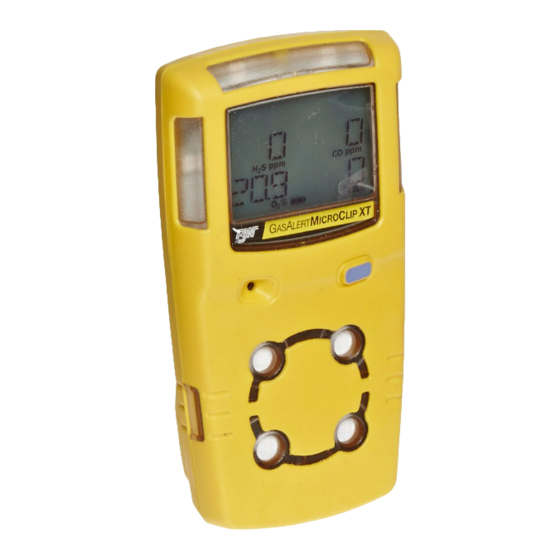
GasAlertMicroClip XT Technical Reference Guide Parts of the GasAlertMicroClip XT Table 3. Parts of the GasAlertMicroClip XT Item Description IntelliFlash Visual alarm indicators (LEDs) Alligator clip Charging connector / IR interface Pushbutton (C) Carbon monoxide (CO) sensor Hydrogen sulfide (H S) sensor Oxygen (O ) sensor... -
Page 20: Display Elements
GasAlertMicroClip XT Display Elements Display Elements Table 4. Display Elements Item Description Alarm condition Automatically zero sensor Numeric value Stealth mode Battery life indicator Gas identifier bars Gas cylinder Automatically span sensor Figure 2. Display Elements... -
Page 21: Pushbutton
GasAlertMicroClip XT Technical Reference Guide Pushbutton Table 5. Pushbutton Pushbutton Description • To activate the detector press C. • To deactivate the detector, press and hold C until the OFF countdown is complete and the LCD deactivates. • To view the TWA, STEL, and peak (maximum) readings, press C twice. To clear the TWA, STEL, and peak readings, press C when the LCD displays RESET. -
Page 22: Activating The Detector
GasAlertMicroClip XT Activating the Detector Activating the Detector Audible/Visual Test a Caution 1. All of the LCD elements display simultaneously as the detector beeps, flashes, vibrates, and activates the back- Only activate the detector in a fresh air environment and in a light. -
Page 23: Startup Message
GasAlertMicroClip XT Technical Reference Guide Startup Message Sensor and Power Test 3. If data is entered in the Startup option (25 characters 5. The detector then tests the sensors. maximum) of Fleet Manager II, that data will display dur- ing the startup self-test. To enter a startup message, refer Detector Identification or the Fleet Manager II Opera- tor’s Manual. -
Page 24: Automatic Zero And O Calibration (Optional)
GasAlertMicroClip XT Activating the Detector Automatic Zero and O Calibration (optional) Note If oxygen is configured to measure 20.8% vol., the oxygen cali- 6. Auto-Zero on Startup: If enabled, the H S, CO, and LEL bration screen displays 20.8% O sensors are automatically zeroed during startup. -
Page 25: Last Calibration Failed (Optional)
GasAlertMicroClip XT Technical Reference Guide Last Calibration Failed (optional) Note If calibration is not performed, or C is not pressed within 2 If any sensor failed the last calibration, CAL FAILURE displays minutes, the detector automatically deactivates. on the screen. If the Force Calibration When Overdue is disabled, press C to acknowledge the warning. -
Page 26: Last Bump Test Failed
GasAlertMicroClip XT Activating the Detector Last Bump Test Failed A bump test must be performed to enter normal operation. Apply gas to the sensors. Ensure the visual, audible, and vibrator If any sensor failed the last calibration, CAL FAILURE displays alarms activate. -
Page 27: Self-Test Pass
GasAlertMicroClip XT Technical Reference Guide Self-Test Pass Battery Test When the detector has passed all startup self-tests, it enters normal The battery is tested when the detector is activated and continuously operation. The LCD displays the ambient gas readings. thereafter. A newly charged battery will typically operate for 10-12 hours. -
Page 28: Deactivating The Detector
GasAlertMicroClip XT Deactivating the Detector Deactivating the Detector To deactivate the detector, press and hold C. The detector • performs a sequence of two sirens with alternating flashes, • vibrates, • initiates the deactivation countdown, and • displays Note If C is released before the countdown is complete, the detec- tor will not deactivate. -
Page 29: Installing Fleet Manager Ii
1. Install Fleet Manager II using the Fleet Manager CD- ROM (available with MicroDock II and the IR Link), or download (at no cost) from BW Technologies by Honey- well website: www.gasmonitors.com. 6. When the Password dialog box displays, enter Admin (password is case sensitive). -
Page 30: Using Fleet Manager Ii To Configure The Detector
GasAlertMicroClip XT Installing Fleet Manager II Using Fleet Manager II to Configure the Detector 9. When the Device Selection dialog box displays, select GasAlertMicroClip / GasAlertMicroClip XT and click When Fleet Manager II is installed, refer to Table Figure 3., and the following procedures: Table 6. - Page 31 GasAlertMicroClip XT Technical Reference Guide 1. Activate the detector and wait for the startup tests to complete. 2. Connect the USB cable to the USB port on the computer. 3. Connect the USB cable to the IR Link. 4. Insert the IR link onto the IR interface on the back of the detector.
-
Page 32: Detector Identification
GasAlertMicroClip XT Detector Identification Detector Identification Hardware/Firmware Revision The Detector Identification section provides information about the Hardware/Firmware Revision cannot be altered. The field automati- detector, current firmware revision, and hardware revision. Data can cally populates when data is retrieved from the detector. If new firmware also be entered (25 characters per line) to display as a startup message is downloaded to the detector, the field automatically updates when data on the detector LCD each time it is activated. -
Page 33: Sensor Configuration
GasAlertMicroClip XT Technical Reference Guide Sensor Configuration Sensor Disabled Settings for the sensors are configured individually. Enter values or a Warning enable/disable options. Refer to Factory Gas Alarm Setpoints for set- Use extreme caution when disabling a sensor. The disabled point values. -
Page 34: Calibration Gas Concentration
GasAlertMicroClip XT Sensor Configuration Calibration Interval 3. Click the Save to Device button located at the bottom of the window. a Caution 4. The detector LCD automatically updates. The gas type BW recommends that the sensors be calibrated once every and sensor readings no longer display on the LCD for the 180 days (6 months). -
Page 35: Bump Interval
GasAlertMicroClip XT Technical Reference Guide Bump Interval High Alarm Define how often a bump check should be performed for each sensor in Enter the high alarm setpoints for each sensor. Refer to Factory Gas the Bump Interval field. A different bump interval can be defined for Alarm Setpoints for factory defined alarm setpoints. -
Page 36: Stel Alarm
GasAlertMicroClip XT Sensor Configuration STEL Interval 2. Enter the setpoint in the TWA Alarm field. STEL Interval provides protection for workers from over exposure to high concentrations of gas, and is based on used-defined 5-15 minute intervals. When the maximum STEL is reached, the detector alarms to notify the worker. -
Page 37: O2 Auto-Calibration On Startup (Automatic O Calibration)
GasAlertMicroClip XT Technical Reference Guide User Options O2 Auto-Calibration on Startup (Automatic O Calibra- tion) The user options section provides detector features that can be enabled or disabled. The green checkmark indicates the option is enabled. Click When enabled, the O sensor is automatically calibrated during the the checkmark to disable the option. -
Page 38: Cal Lock (Calibration Ir Lock)
GasAlertMicroClip XT User Options Cal Lock (Calibration IR Lock) Confidence Beep When enabled, the sensors can only be calibrated using an infrared (IR) When enabled, the confidence beep provides continuous audible confir- device to ensure calibrations are recorded. The following are IR mation that the detector is operating correctly by beeping once every devices: second. -
Page 39: Force Bump When Overdue
GasAlertMicroClip XT Technical Reference Guide Force Calibration When Overdue with the IR Link. This option is available only if configuring the GasAlertMicroClip with the base station. Default interval is 15 seconds. When enabled, if a sensor(s) is past due, the sensor(s) must be cali- brated immediately, otherwise the detector deactivates. -
Page 40: Intelliflash
GasAlertMicroClip XT User Options IntelliFlash Press C to acknowledge the low alarm and deactivate the audible alarm. When enabled, the green LED flashes to provide continuous visual con- Note firmation that the detector is operating correctly. Low Alarm Acknowledge is not applicable to O Note IntelliFlash is only applicable to GasAlertMicroClip XT. -
Page 41: Stealth Mode
GasAlertMicroClip XT Technical Reference Guide Language Menu Stealth Mode The detector can display warnings and notifications in five different lan- When enabled, the backlight, visual alarms, and audible alarms are dis- guages. Refer to the following illustration. abled. displays continuously on the LCD. During an alarm, the vibrator activates and readings display on the LCD. -
Page 42: Alarms
GasAlertMicroClip XT Alarms Alarms Table 7. describes the detector alarms and corresponding screens. During an alarm condition, the detector activates the backlight, audible/visual/ vibrator alarms, and displays the current ambient readings. If more than one type or level of alarm occurs simultaneously, a multi-gas alarm results. If Stealth is enabled, the audible and visual alarms are disabled, and only the vibrator alarm activates. - Page 43 GasAlertMicroClip XT Technical Reference Guide Alarm Screen Alarm Screen Over Limit (OL) Alarm Multi-Gas Alarm • Fast siren and alternating flash • Sequence alternating low and high alarm siren and flash • L and gas bar flash • L and gas bars flash •...
-
Page 44: Computed Gas Exposures
GasAlertMicroClip XT Alarms Computed Gas Exposures Viewing Gas Exposures a Warning To view the TWA, STEL, and peak (maximum) readings, press C twice. The LCD first displays the TWA gas exposures. To avoid possible personal injury, do not deactivate the detector during a work shift. -
Page 45: Clearing Gas Exposures
GasAlertMicroClip XT Technical Reference Guide Clearing Gas Exposures Gas Alarm Setpoints a Caution Gas alarms are activated when detected gas concentrations are above or below the user-defined setpoints. Gas alarms are described below. Follow all safety procedures as defined by your employer. Confirm with your supervisor before clearing TWA and STEL Table 9. -
Page 46: Factory Gas Alarm Setpoints
GasAlertMicroClip XT Alarms Factory Gas Alarm Setpoints Changing Alarm Setpoints Note To change alarm setpoints, use the base station or IR Link and refer to the following under Sensor Configuration: Standard factory alarm setpoints may vary by region. • Low Alarm Table 10. -
Page 47: Sensor Alarm
GasAlertMicroClip XT Technical Reference Guide Sensor Alarm • If battery power becomes critically low, L and dis- LOW BAT play. The detector performs a sequence of 10 rapid sirens with 1 The detector tests for missing or defective sensors during the startup second of silence in between (sequence reactivates seven times). -
Page 48: Bump Test
GasAlertMicroClip XT Bump Test Bump Test... -
Page 49: Calibration
• Allow the detector to stabilize for 1 minute after activation before performing a calibration or bump test. Guidelines • If a certified calibration is required, contact BW Technologies by Honeywell. When calibrating the detector, adhere to the following guidelines: • Recommended gas mixture:... -
Page 50: Connecting The Gas Cylinder To The Detector
GasAlertMicroClip XT Calibration Connecting the Gas Cylinder to the Detector Table 11. Connecting the Gas Cylinder to the Detector Refer to the following Figure Table 11., and procedures to connect Item Description the gas cylinder to the detector for calibration. Calibration cap Note Calibration hose... -
Page 51: Calibration Setup
GasAlertMicroClip XT Technical Reference Guide Calibration Setup 3. Insert the IR Link into the IR interface on the back of the detector. Refer to Figure 9. The following calibration procedures are written as calibration perfor- mance is intended. If an error or failure occurs, refer to Calibration Trou- bleshooting. -
Page 52: Calibrating With The Ir Link
GasAlertMicroClip XT Calibration Calibration Procedure 8. Ensure the sensors to be calibrated are enabled in Fleet Manager II. a Caution Only calibrate in a fresh air environment and in a safe area. Do 9. Using , select the concentration value(s) in the not calibrate the detector during or immediately after charging. -
Page 53: Auto Zero And Oxygen Sensor Calibration
GasAlertMicroClip XT Technical Reference Guide Auto Zero and Oxygen Sensor Calibration Auto Span Note 4. When auto zero is complete, APPLY GAS displays. Do not apply calibration gas until APPLY GAS displays, other- wise the auto zero function will fail. flashes while the detector zeroes the combusti- ble and toxic sensors, and calibrates the oxygen sensor. -
Page 54: Calibration Due Date
GasAlertMicroClip XT Calibration When a sufficient amount of gas has been detected (approxi- Successful Span mately 30 seconds after the gas has been applied), the detector If the sensors have spanned successfully, the detector beeps and the beeps once, flashes, and K remains lit while the detec- calibration procedure continues. - Page 55 GasAlertMicroClip XT Technical Reference Guide 6. After calibration is complete, CAL DUE displays and all Failed Sensor Past Calibration Due Date: If a sensor fails the span successfully calibrated sensors automatically reset the and it is past the calibration due date, the following three screens dis- calibration due dates according to the calibration inter- play.
-
Page 56: Verification
GasAlertMicroClip XT Calibration Verification 1. After calibration is complete and the detector returns to normal operation, verify the calibration using a gas cylin- der other than the one used for calibration. 2. The gas concentration should not exceed the sensor's detection range. -
Page 57: Datalogs
GasAlertMicroClip XT Technical Reference Guide Datalogs Software Requirements The detector records various information that can be compiled to create To create spreadsheet reports of event logs, datalogs, and bump and a report. The detector is capable of storing 16 hours of information calibration results, the following software applications are required: (when recording a datalog every 15 seconds). -
Page 58: Battery Cautions
GasAlertMicroClip XT Maintenance Battery Cautions Charging the Battery a Warning To charge the battery, refer to Figure 10., Table 12., and the following procedures (1-8). To avoid personal injury and/or property damage, adhere to the following: • The detector must be deactivated to charge the battery. •... - Page 59 GasAlertMicroClip XT Technical Reference Guide Table 12. Connecting the Charging Adapter 5. When charging is complete, the charging indicator stops flashing and displays to indicate a full charge. Item Description Remove the charging adapter and activate the detector. Detector If the battery indicator does not display, refer to Troubleshooting. 6.
-
Page 60: Replacing A Sensor Or Sensor Filter
GasAlertMicroClip XT Maintenance Replacing a Sensor or Sensor Filter a Warning To avoid personal injury, only use sensors that are specifically designed for the detector. Refer to Replacement Parts and Accessories. Use proper ESD handling practices. • Each sensor has a high degree of resistance to common vapors and gases. -
Page 61: Replacing The Sensor Filter
GasAlertMicroClip XT Technical Reference Guide Replacing the Sensor Filter Table 13. Replacing a Sensor or Sensor Filter 1. Note the placement of the PCB to ensure it is replaced Item Description correctly. Remove the two screws on the PCB. Remove Front shell the PCB carefully. -
Page 62: Replacing The Oxygen Sensor
GasAlertMicroClip XT Maintenance Note 1. Gently remove the circular rigidified flex PCB atop the sensor from the metal sensor posts. Take care not to tear Detectors that are configured for 1, 2, or 3 gases may the flex cable. contain a dummy sensor in one of the four sensor locations. 3. -
Page 63: Reassembling The Detector
GasAlertMicroClip XT Technical Reference Guide 5. Carefully replace the circular rigidified flex PCB atop the metal sensor posts. Ensure the purple plastic sensor post is inserted into the clear plastic hole. Take care not to tear the flex cable. 6. Press down to secure the circular rigidified flex PCB atop the metal sensor posts.Take care not to press down too hard and accidentally activate the detector. -
Page 64: Troubleshooting
GasAlertMicroClip XT Troubleshooting Troubleshooting If a problem occurs, refer to the solutions in the Troubleshooting section. If the problem persists, contact BW Technologies by Honeywell Table 14. Troubleshooting Problem Possible Cause Solution Startup The detector does not activate. Depleted battery Charge battery. - Page 65 GasAlertMicroClip XT Technical Reference Guide Table 14. Troubleshooting Problem Possible Cause Solution Detector Operation Detector does not display expected Sensor not stabilized Used sensor: wait 60 seconds gas readings after activation self-test. New sensor: wait 5 minutes Sensor(s) requires calibration Calibrate the sensor(s).
- Page 66 Charge the battery for 8 hours. Detector LEDs when charging. may light during first 5 hours. This is normal. If the battery indicator does not light after charging for 8 hours, contact BW Technologies by Honey- well. When detector is activated after Battery is defective Contact BW Technologies by Honeywell.
-
Page 67: Startup Troubleshooting
GasAlertMicroClip XT Technical Reference Guide Startup Troubleshooting Error Screen Problem Solution Error Screen Problem Solution Sensor Error Calibrate the sensor(s). IR Lock Enabled Perform calibration using the Refer to Calibration. Reacti- If the IR Lock screen IR Link with Fleet Manager II The sensor failed dur- vate the detector. -
Page 68: Calibration Troubleshooting
GasAlertMicroClip XT Calibration Troubleshooting Calibration Troubleshooting Error Screen Problem Solution Error Screen Problem Solution Auto-zero Attempt calibration again. No Gas Detected Ensure the sensor is enabled. Unsuccessful Refer to Calibration. If If the applicable gas is Verify gas cylinder is not ERROR displays again, S, CO, or LEL sen- not detected within 2... -
Page 69: Replacement Parts And Accessories
GasAlertMicroClip XT Technical Reference Guide Replacement Parts and Accessories Model No. Description a Warning Gas Cylinders To avoid personal injury and/or damage to the detector, use only the specified replacement parts. Quad gas cylinder: CH (2.5%), (18.0%), H S (25 ppm), CO (100 To order parts or accessories listed in the following table, contact CG-Q58-4 Technologies by... - Page 70 GasAlertMicroClip XT Replacement Parts and Accessories Model No. Description Model No. Description GA-PA-3 12-24 VDC direct-wire power adapter Sampling/Testing Equipment GA-PA-1* Replacement power adapter GA-SPAK02 SamplerPak (motorized sampling pump kit) GA-VPA-1 Vehicle charging kit Manual aspirator pump kit with probe MC-AS01 (1 ft.
-
Page 71: Specifications
GasAlertMicroClip XT Technical Reference Guide Specifications Backlight: Activates when the pushbutton is pressed and deactivates after 5 seconds; also activates during an alarm condition Instrument dimensions: 11.25 x 6.00 x 2.89 cm (4.4 x 2.4 x 1.1 in.) Self-test: Initiated upon activation Weight: 170 g (6.0 oz.) Calibration: Automatic zero and automatic span Operating temperature: -20°C to +58°C (-4°F to +136°F) -
Page 72: General Datalogger Specifications
GasAlertMicroClip XT Specifications General Datalogger Specifications Approvals: Approved by CSA to both U.S. and Canadian Standards Storage: 16 hours at 15-second intervals CAN/CSA C22.2 No. 157 and C22.2 152 ANS/UL – 913 and ANSI/ISA – S12.13 Part 1 Memory type: Wraparound memory ensures most recent data is Class I, Division 1, Group A, B, C, and D always saved ATEX... - Page 73 GasAlertMicroClip XT Technical Reference Guide...
- Page 74 131475-L3 D6568/0 [English] © BW Technologies 2010. All rights reserved.
Need help?
Do you have a question about the MicroClip XT and is the answer not in the manual?
Questions and answers