Table of Contents
Advertisement
Advertisement
Table of Contents

Related Manuals for ELNA 9900


Summary of Contents for ELNA 9900
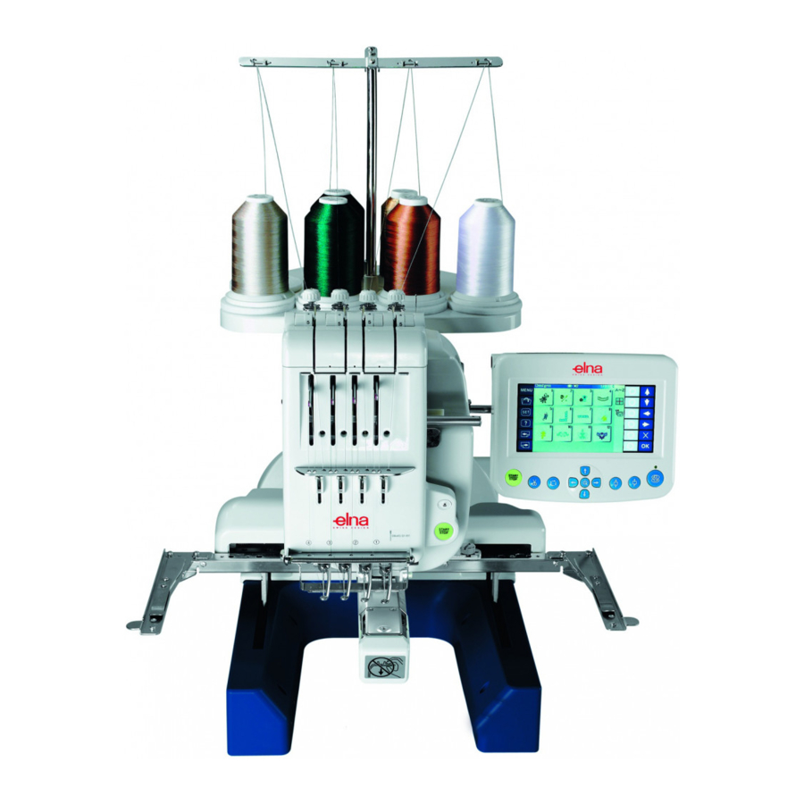
- Page 1 SERVICE MANUAL 9900...
-
Page 2: Table Of Contents
9900 CONTENTS Replacing the Spool Stand ................... Replacing the Tension Unit Cover ................Replacing the Static head cover (Right)............... To Replace Right Cover and Left Cover............... Replacing the Base Cover and Bed Cover ..............Checking the Thread Paths (1) .................. - Page 3 9900 CONTENTS Adjusting a Play in the Moving Head ................. Replacing the Moving Head (1) .................. Replacing the Moving Head (2) .................. Adjusting the Needle Drop Position (Back or Forth) ..........Adjusting the Needle Height ..................Replacing the Needle Bar, Needle Spring and Cushion ..........
- Page 4 9900 CONTENTS Adjusting the Static Cutter Blade ................Adjusting the Dynamic Cutter Blade ................Adjusting the Bobbin Thread Holder ................Adjusting the Thread Keeper ..................Adjusting the X-carriage Belt Tension ................ Replacing the X-carrige Belt ..................Adjusting the Y-carriage Belt Tension .................
-
Page 5: Replacing The Spool Stand
9900 Replacing the Spool Stand Setscrews To remove: 1. Remove the 3 setscrews and spool stand. To attach: 2. Attach the spool stand and tighten the 3 setscrws. Spool stand Replacing the Tension Unit Cover Tension unit cover To remove: 1. -
Page 6: Replacing The Static Head Cover (Right)
9900 Replacing the Static Head Cover (Right) Caps, Setscrews (A) To remove: 1. Loosen the RCS mounting arm knob and remove it. 2. Remove 2 caps, and 2 setscrews (A). Remove the static head cover (right). 3. Disconnect the LED lamp connector and K-board connector. -
Page 7: To Replace Right Cover And Left Cover
9900 To Replace Right Cover and Left Cover Upper hook 2 Upper hook 1 Right Cover To remove: 1. Remove the static head cover (right). Unhook the right cover from the right hook. • To remove the static head cover (right), Unhook the cover from upper hook 1, upper hook 2 and the hook on handwheel side. -
Page 8: Replacing The Base Cover And Bed Cover
9900 Replacing the Base Cover and Bed Cover Setscrews A Base Cover To remove: 1. Remove the 6 setscrews A. 2. Lift the back of the machine and pull out the base cover (support the back of the machine with a crosstie). -
Page 9: Checking The Thread Paths (1)
9900 Checking the Thread Paths (1) To avoid seam puckering, skipped stitches or thread breaking, keep the thread paths in the best condition (free from burr, scratch, rust etc.). 1. Tension control, detecting roller a) Detecting rollers should spin smoothly. -
Page 10: Checking The Thread Paths (2)
9900 Checking the Thread Paths (2) Upper side 6. Needle plate a) There should be no burrs or scratches. Lower side 7. Presser foot a) There should be no burrs or scratches, especially inside of the presser foot hole. -
Page 11: Replacing The Needle
9900 Replacing the Needle Needle clamp screw To remove: 1. Loosen the needle clamp screw. 2. Remove the needle. Needle To attach: 3. Insert the needle into the needle clamp with the long groove facing you. Push the needle up as far as it will go. -
Page 12: Needle And Thread Reference Table
9900 Needle and Thread Reference Table Use DBxK5Q1NY needles and select an appropriate size of needle for threads and fabrics to be sewn. An inappropriate size of needle may cause skip stitches, thread breakage or thread looping. Please refer to the table below and select the suitable needle size. -
Page 13: Checking The Lowest Position Of The Needle
9900 Checking the Lowest Position of the Needle 1. Remove the spool stand, static head cover (right) and left cover. 2. Turn the handwheel to set the index disk at 270°. 3. Push the needle bar down to engage the needle bar clutch. -
Page 14: Replacing The Needle Bar Rest
9900 Replacing the Needle Bar Rest Connector Setscrews (A) To remove: 1. Remove the spool stand, static head cover (right), right cover and left cover. 2. Disconnect the thread catcher unit connector. Remove the 3 setscrews (A). Remove the thread catcher unit. -
Page 15: Replacing The Take-Up Lever Cam Roller
9900 Replacing the Take-up Lever Cam Roller Setscrews Connector Drive cover To remove: 1. Remove the spool stand, static head cover (right), right cover, left cover and thread tension panel. 2. Remove the 3 setscrews and drive cover. Thread take-up lever spring 3. -
Page 16: Adjusting The Take Up Lever Timing
9900 Adjusting the Take-up Lever Timing To remove: 1. Remove the spool stand, static head cover (right), right cover and left cover. 2. Turn the handwheel to set the index disk at 6º. 3. Insert the positioning pin from the left side of the arm. -
Page 17: Replacing And Adjusting The Presser Foot (1)
9900 Replacing and Adjusting the Presser Foot (1) 1. Remove the lower thread guide plate unit and thread catcher panel. 2. Loosen the needle clamp screw and the setscrew. Remove the needle, needle clamp and two needle clamp cushions. -
Page 18: Replacing And Adjusting The Presser Foot (2)
9900 Replacing and Adjusting the Presser Foot (2) 7. Turn the handwheel to set the index disk at 0º (L). 8. Insert the 1.2 mm thick gauge between the needle plate and the presser foot. 9. Tighten the setscrew. -
Page 19: Replacing The Thread Catcher Unit
9900 Replacing the Thread Catcher Unit To remove: 1. Remove spool stand, head cover (right), right cover, left cover, moving head and lateral Connector moving unit. Setscrews (A) 2. Disconnect the thread catcher connector. Remove the 3 setscrews (A), the thread catcher. -
Page 20: Replacing The Thread Catcher Hook
9900 Replacing the Thread Catcher Hook To remove: 1. Remove the thread catcher unit (see page 18). 2. Loosen the 6 setscrews and remove the thread catcher guide. 3. Remove the thread catcher hook screw. Remove the thread catcher hook. -
Page 21: Replacing The Jump Solenoid
9900 Replacing the Jump Solenoid 1. Remove the static head cover (right). Setscrews 2. Disconnect the connector. Remove the 3 setscrews and jump solenoid. Connector Slope cam 3. The slope cam should slide on the slope cam guide smoothly. Clean the solenoid if there is any lint or dust on it. -
Page 22: Adjusting A Play In The Moving Head
9900 Adjusting a Play in the Moving Head 1. Remove the static head cover (right). Needle drop adjusting rail 2. Check the play in the direction of the arrows. If there is a detectable play, loosen the setscrew and tighten it while pressing the adjusting roller against the needle drop adjust- ing rail. -
Page 23: Replacing The Moving Head (1)
9900 Replacing the Moving Head (1) To remove: Cord clamp Setscrew 1. Remove the spool stand, static head cover Connector (right), right cover and left cover. 2. Disconnect the connectors. Remove the setscrew of the cord clamp. Connector Connector Idler gear 3. -
Page 24: Replacing The Moving Head (2)
9900 Replacing the Moving Head (2) 6. Turn the handwheel to set the index disk at 270º. 7. Turn the idler gear to set the moving head to the needle bar No. 3. Push the needle bar No. 3 down to engage the needle bar clutch. -
Page 25: Adjusting The Needle Drop Position (Back Or Forth)
9900 Adjusting the Needle Drop Position (Back or Forth) 1. Set the moving head to needle bar No. 3 (see pages 26 and 39 of the instruction book). Push the needle bar No. 3 down to engage the needle bar clutch. -
Page 26: Adjusting The Needle Height
9900 Adjusting the Needle Height 1. Remove the lower thread guide plate and thread catcher panel. 2. Remove the bobbin case. 3. Push the needle bar down to engage the needle bar clutch. 4. Turn the handwheel to set the index disk at 0º (L). -
Page 27: Replacing The Needle Bar, Needle Spring And Cushion
9900 Replacing the Needle Bar, Needle Spring and Cushion 1. Remove the presser foot (see pages 16 and 17). Needle bar 2. Loosen the needle bar holder screw. Needle bar spring 3. Pull the needle bar up and out of the frame. -
Page 28: Replacing The Rotation Stopper Plate
9900 Replacing the Rotation Stopper Plate To remove: 1. Remove the moving head (see pages 22 and 23). 2. Remove the 6 setscrews and rotation stopper Setscrews plate. To attach: 3. Attach the rotation stopper plate with the 6 setscrews. -
Page 29: Replacing The Thread Take-Up Lever
9900 Replacing the Thread Take-up Lever 1. Remove the moving head (see pages 22 and 23). Setscrew 2. Remove the E-ring. 3. Loosen the setscrew on the thread take-up lever shaft. 4. Pull the thread take-up lever shaft out in the direction of the arrow. -
Page 30: Adjusting The Check Spring Tension
9900 Adjusting the Check Spring Tension Check spring tension is not necessary to adjust under normal conditions. However, you need to adjust the tension of the check spring when it is replaced. 1. Remove the 2 setscrews (A) and lower thread Setscrew guide plate. -
Page 31: Adjusting The Check Spring Stroke
9900 Adjusting the Check Spring Stroke Check spring stroke is not necessary to adjust under normal conditions. However, you need to adjust the stroke of the check spring when it is replaced. 1. Loosen the setscrew. Move the adjuster up or... -
Page 32: Adjusting The Thread Catcher Holder
9900 Adjusting the Thread Catcher Holder 1. Remove the static head cover (right) (see page 5). Setscrews (A) Rod shaft 2. Remove the thread catcher panel and lower thread guide plate (see pages 18 and 19). 3. Loosen the 4 setscrews (A). -
Page 33: Replacing The Thread Catcher Loop Tape
9900 Replacing the Thread Catcher Loop Tape 1. Remove the static head cover (right) (see page 5). 2. Remove the thread catcher panel and lower thread guide plate (see pages 18 and 19). Setscrews (A) 3. Remove the 4 setscrews (A) and remove the thread catcher holder unit. -
Page 34: Replacing The Lateral Moving Unit
9900 Replacing the Lateral Moving Unit To remove: 1. Remove the spool stand, static head cover (right), Setscrews (A) right cover and left cover (see pages 4 and 5). Connector 2. Remove the tension unit cover (see page 4). -
Page 35: Adjust The Hook Timing
9900 Adjusting the Hook Timing 1. Remove the 2 setscrews and needle plate. Setscrews 2. Loosen the 3 setscrews on the hook. 3. Select No. 3 needle bar in the Ready to Sew mode (see pages 29 and 36 of the instruction book) and push the needle bar down. -
Page 36: Adjusting The Position Of The Hook Stopper
9900 Adjusting the Position of the Hook Stopper 1. Loosen the hexagonal socket screw (2 mm) to move the hook stopper. 2. Move the hook stopper to align the center with the needle and make a 0.65 – 0.95 mm clearance Setscrew between the hook and hook stopper. -
Page 37: Replacing The Thread Cutter Driving Roller
9900 Replacing the Thread Cutter Driving Roller 1. Remove the spool stand, static head cover (right) and right cover (see pages 4 – 6). 2. Loosen the setscrew and remove the pivot pin. Remove the lever unit from the frame. -
Page 38: Replacing The Dynamic Cutter Blade
9900 Replacing the Dynamic Cutter Blade 1. Remove the 2 setscrews and needle plate. Setscrews 2. Turn the power switch on while pressing the Start/ Stop button and Thread cutter button at the same time to open the Factory Adjusting window. -
Page 39: Replacing The Static Cutter Blade
9900 Replacing the Static Cutter Blade 1. Remove the setscrews and needle plate. Setscrews 2. Press Divide key to move the dynamic cutter blade forward. 3. Remove the two setscrews and replace the static cutter blade. 4. Attach the static cutter blade and tighten the set screws while pressing the static cutter blade in the direction of the arrow. -
Page 40: Adjusting The Static Cutter Blade
9900 Adjusting the Static Cutter Blade Setscrew 1. Remove the 2 setscrews and needle plate. 2. Press Init key to move the dynamic cutter blade to the home position. 3. Check if there is any thrust play in the cutter drive shaft and eliminate a play if any. -
Page 41: Adjusting The Dynamic Cutter Blade
9900 Adjusting the Dynamic Cutter Blade Setscrews 1. Remove the spool stand, static head right cover, right cover and left cover (see pages 4 – 6). 2. Remove the two setscrews and needle plate. 3. Press Divide key to move the dynamic cutter blade to the home position. -
Page 42: Adjusting The Bobbin Thread Holder
9900 Adjusting the Bobbin Thread Holder 1. Remove the 2 setscrews and needle plate. Setscrews 2. Place the bobbin thread between the dynamic cutter blade and bobbin thread holder. Close the dynamic cutter blade to clamp the bobbin thread. -
Page 43: Adjusting The Thread Keeper
9900 Adjusting the Thread Keeper Gauge bobbin 1. Insert the gauge bobbin (a 1.6 mm thick spacer stuck on it) into the bobbin case and insert the bobbin case into the hook. 2. Loosen the 2 setscrews (A) and insert a 2 mm thick gauge between the frame of the solenoid and washer on the plunger. -
Page 44: Adjusting The X-Carriage Belt Tension
9900 Adjusting the X-carriage Belt Tension 1. Remove the spool stand, static head right cover, right cover and left cover (see pages 4 – 6). X-carriage cover 2. Loosen the 2 setscrews (A) and remove the X-carriage cover. 3. Shift the hoop supporter to the extreme left end. Set the push-pull gauge at the right side of the machine frame and push the X-carriage timing belt. -
Page 45: Replacing The X-Carrige Belt
9900 Replacing the X-carriage Belt 1. Remove the spool stand, static head right cover, right cover and left cover (see pages 4 – 6). 2. Loosen the 2 setscrews (A) and remove the X-carriage cover. 3. Shift the hoop supporter to the extreme right end. -
Page 46: Adjusting The Y-Carriage Belt Tension
9900 Adjusting the Y-carriage Belt Tension 1. Remove the spool stand, static head right cover, hight cover and left cover (see pages 4 – 6). 2. Shift the X-carriage to the extreme front end. Push-pull gauge 3. Set the push-pull gauge in line with the front end of the base frame and push the Y-carriage timing belt. -
Page 47: Replacing The Y-Carrige Belt
9900 Replacing the Y-carriage Belt 1. Remove the spool stand, static head right cover, right cover and left cover (see pages 4 – 6). 2. Remove the 2 setscrews (B) and the Y-belt holder. Setscrews (B) 3. Loosen the 2 setscrews (A) and shift the Y-belt pulley in the direction of the arrow. -
Page 48: Adjusting The Timing Belt Tnsion
9900 Adjusting the Timing Belt Tension Push-pull gauge Timing belt 1. Remove the spool stand, static head right cover and left cover (see pages 4 – 6). 2. Place a scale on the DC motor. Set the push-pull gauge in line with the scale as illustrated and push the timing belt. -
Page 49: Replacing The Timing Belt
9900 Replacing the Timing Belt 1. Remove the spool stand, static head right cover, right cover and left cover (see pages 4 – 6). Setscrews (A) Pointer 2. Remove the 2 setscrews (A) and the pointer. 3. Remove the 3 setscrews (B) and CPU board. -
Page 50: Adjusting The Motor Belt Tension
9900 Adjusting the Motor Belt Tension 1. Remove the spool stand, static head right cover, right cover and left cover (see pages 4 – 6). 2. Place a scale under the stud bolt. Set the push-pull gauge in line with the scale as illustrated and push Motor belt the timing belt. -
Page 51: Replacing The Motor Belt
9900 Replacing the Motor Belt 1. Remove the spool stand, static head right cover, right cover and left cover (see pages 4 – 6). 2. Remove the 2 setscrews (A) and the pointer. Pointer Setscrews (A) 3. Remove the three setscrews (B) and DC motor. -
Page 52: Replacing The Dc Motor
9900 Replacing the DC Motor 1. Remove the spool stand, static head right cover, right cover and left cover (see pages 4 – 6). 2. Disconnect the motor connector. Remove the 3 setscrews (A) and DC motor. DC motor 3. -
Page 53: Adjusting The Needle Upper Shaft Timing
9900 Adjusting the Upper Shaft Timing 1. Remove the spool stand, static head cover (right) and right cover (see pages 4 and 6). 2. Open the factory adjusting menu window and press the Phase key to open the Phase Sensor adjusting window. -
Page 54: Adjusting The Moving Head Stop Position
9900 Adjusting the Moving Head Stop Position 1. Remove the spool stand, static head cover (right), 770 A:1.00 K 001J Ver.040 right cover, left cover and tension control panel (see Needle Change pages 4 – 6). NCHM Init Sen NCHM No. -
Page 55: Adjusting The Needle Stop Position
9900 Adjusting the Needle Stop Position 1. Remove the spool stand, static head cover (right), 770-A:1.00-K-001J Ver.040 right cover, left cover and tension control panel (see Needle Change pages 4 – 6). NCHM Init Sen NCHM No. Sen 2. Turn the lateral movement idler gear to select needle bar No. -
Page 56: Adjusting The Carriage Home Position (1)
9900 Adjusting the Carriage Home Position (1) 1. Remove the spool stand, right cover, left cover, base cover and X-carriage cover (see pages 4 – 7). 2. Place the master template in the embroidary hoop. 3. Open the factory adjusting menu window and press the X/Y Motor key to open the X/Y Motor adjusting window. -
Page 57: Adjusting The Carriage Home Position (2)
9900 Adjusting the Carriage Home Position (2) [When the needle drop position C-1 is not centered although the needle drop position C is centered.] 1 Loosen setscrews A. Remove the X-carriag sensor plate. 2 Loosen the hexagonal socket screws B.
Need help?
Do you have a question about the 9900 and is the answer not in the manual?
Questions and answers