Table of Contents
Advertisement
Quick Links
Advertisement
Table of Contents

Related Manuals for Pulsar ULTRA TWIN


Summary of Contents for Pulsar ULTRA TWIN
- Page 1 ULTRA T (UL) NSTRUCTION ANUAL...
- Page 3 ARRANTY AND IABILITY Pulsar Process Measurement Limited guarantee for a period of 2 years from the date of delivery that it will either exchange or repair any part of this product returned to Pulsar Process Measurement Limited if it is found to be defective in material or workmanship, subject to the defect not being due to unfair wear and tear, misuse, modification or alteration, accident, misapplication or negligence.
-
Page 5: Table Of Contents
Wall mount ............................22 Fascia mount ............................22 Preparation for Operation ..........................23 Maintenance ..............................24 Chapter 3 How To Use Your Ultra Twin ......................25 Operating the Controls ..........................25 Display ..............................25 Run Mode .............................. 27 Program Mode ............................27 How to Access Program Mode ........................ - Page 6 Example 2 BS3680 U-Throated Flume ....................79 BS3680 Thin Plate Weirs ..........................81 Point of Measurement ........................... 81 Calculations ............................81 Example 3 BS3680 Rectangular Weir ....................83 BS3680 Rectangular Broad Crested Weir ....................85 Point of Measurement ........................... 85 Calculations ............................
- Page 7 Totaliser Audits ............................ 143 Temperature ............................143 Pump Logs ............................144 Volume................................. 145 Conversion ............................146 Breakpoints ............................150 Tables ..............................151 OCM Parameters ............................152 PMD Setup............................152 Dimensions ............................155 Calculations ............................158 Breakpoints ............................159 Tables ..............................159 Average Flow ............................
- Page 8 RS232 Set Up ............................191 RS 485 Set Up (Optional) ........................191 Remote Alarm............................192 Test Parameters ............................193 Simulation ............................193 Test Setup ............................. 194 Hardware .............................. 195 Chapter 6 Troubleshooting ..........................197 Parameter Record .............................. 199...
-
Page 9: Chapter 1 Start Here
Chapter 1 Start Here… Congratulations on your purchase of a Pulsar Ultra Twin. This quality system has been developed over many years and represents the latest in high technology ultrasonic level measurement and control. It has been designed to give you years of trouble free performance, and a few minutes spent reading this operating manual will ensure that your installation is as simple as possible. -
Page 10: About The Ultra Twin
Ultra Twin sends a transmit pulse to the transducer(s), which emits an ultrasonic pulse perpendicular to the transducer face, and the returned echo is sent back to the Ultra Twin. The time taken to receive the echo is measured and the distance from the transducer face to the surface being monitored is calculated. - Page 11 PLC, to monitor level space, distance, volume, OCM head or flow (dependant on the application chosen), independently from that shown on the display. There is an RS232 port, so that the Ultra Twin can be operated remotely by a PC or other equipment.
-
Page 12: Product Specification
Product Specification Physical Wall Mount Overall Outside dimensions 9.25 x 7.24 x 4.72 inch (235 x 184 x 120 mm) Weight Nominal 2.2lbs (1 kg) Enclosure material/description Polycarbonate, flame resistant to UL94-5V Cable entry detail 10 cable entry knock outs, 5 x M20, 1 x M16 underside 4 x PG11 at rear Fascia Mount... - Page 13 4000A breaking capability to comply with certification of the Exm version of dB series transducers. Pulsar Process Measurement Limited operates a policy of constant development and improvement and reserve the right to amend technical details as necessary. Page...
-
Page 14: Ec Declaration Of Conformity
EC Declaration of Conformity Wall Mount Page... -
Page 15: Fascia Mount
Fascia Mount Page... - Page 16 This page left blank intentionally Page...
-
Page 17: Chapter 2 Installation
Chapter 2 Installation Power Supply Requirements The Ultra Twin can operate from AC supply or from a DC battery and is designed for use in temperatures between -4 F to +140 F (-20 C to +50 The AC is 115 +5% / -10% 50/60Hz. The DC is 18-30V. In all cases the Ultra Twin will typically consume 6W of power, with a maximum of 10W. -
Page 18: Location
All electronic products are susceptible to electrostatic shock, so follow proper grounding procedures during installation. Ultra Twin must be mounted in a non-hazardous (safe) area, and the transducer fitted in the hazardous area. FM APPROVED TRANSDUCERS Class I, Div. 1, Group A, B, C & D Class II, Div. -
Page 19: Dimensions
Wall mount The dimensions of the wall fixing holes are as shown below. The Ultra Twin should be mounted by drilling three holes suitable for size 8 screws (length to suit your application), and fixing the top screw in place. - Page 20 The full dimensions of the enclosure are as shown below Page...
- Page 21 Cable Entry There are 6 cable gland knock-outs on the base of the wall mount Ultra Twin (5 x 0.79" (20mm), 1 x 0.63" (16mm)) and 4 on the rear (4 x 0.73" (18mm)). Select which ones you wish to use, and remove them by using a circular cutter, such as a tank cutter.
-
Page 22: Fascia Mount
Fascia Mount The Fascia mount Ultra Twin should be installed by cutting a hole in the panel, as detailed below, and securing the unit with the fixings supplied. The full dimensions of the Fascia mount enclosure are as shown below. -
Page 23: Terminal Connection Details
Important Information When mounting the fascia mount unit in to a panel, in order to maintain the panel IP rating the panel should be of smooth/painted finish and be machined, as per the details contained in this manual. Fit the unit through the hole then, using the components supplied place a plain washer then a spring washer followed by an elongated nut to each of the 4 off M3 threaded studs and tighten to 2.5lb in. -
Page 24: Fascia Mount
Fascia Mount Page... - Page 25 Care should be taken not to overtighten the screws. Power The Ultra Twin can operate from mains AC and automatically from DC or battery backup in the event of power failure, or can be operated permanently from DC or batteries.
- Page 26 The entire range of, standard dB transducers are certified for use in hazardous areas and different models, for each, are available for use in Zone 1 or Zone 0. Wire the transducer to the Ultra Twin’s transducer terminals, terminal numbers will depend on the unit type, as follows: Transducer 1...
- Page 27 When installing a transducer in a hazardous area use an approved transducer, from the Pulsar dB range, suitable for the proposed application. For EEx m (Zone 1) applications a transducer certified to FM Class I Div 1 Group A, B, C & D, ClassII Div 1 Group E, F & G, Class III is used, and must be supplied via a 1500A breaking fuse, which is fitted as standard to the blackbox level controller.
- Page 28 Digital Inputs Where the Ultra Twin is required to provide power for a Device Input the appropriate Digital Input should be wired between the 24VDC supply terminal and the IN terminal. (TOTAL maximum current available, for all digital inputs, four on Wall Mount model and seven on Fascia Mount model, from the 24VDC supply is 24mA).
- Page 29 -25ºC to 50ºC Type B -25ºC to 125ºC The temperature sensor should be placed close to the point of measurement. The unit is connected as follows: Description Temperature Sensor Ultra Twin Power Supply Terminal 1 Terminal 27 Return Terminal 2 Terminal 28...
-
Page 30: Fuse Location
Fuse Location Wall mount The mains fuse is located, inside the terminal compartment, to the left of the mains terminals, as illustrated below. Fascia mount The mains fuse is located under the removable cover at the bottom of the unit, as illustrated below Page... -
Page 31: Preparation For Operation
Preparation for Operation Before switching on, check the following: The Ultra Twin is mounted correctly and is in a ‘safe’ area. The power supply is correctly installed.. The relays are connected correctly. -
Page 32: Maintenance
Maintenance There are no user serviceable parts inside your Ultra Twin, except the mains fuse. If you experience any problems with the unit, then please contact Pulsar Process Measurement for advice. Important Information Please note that the onboard Lithium battery, mounted to the processor PCB, is not user serviceable. -
Page 33: Chapter 3 How To Use Your Ultra Twin
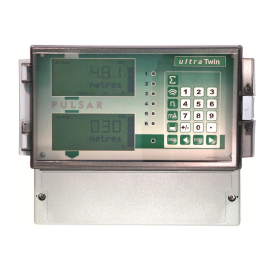
Ultra Twin Chapter 3 How To Use Your Operating the Controls Display On the wallmount model there are two identical displays, by default, the top display will provide information on the current mode of operation, and status of the remote communication for point 1 (transducer 1), while the bottom display provides the same information for point 2 (transducer 2). - Page 34 Run Mode Program Mode Test Mode 100% 000.000 XXXXXXXXXXXX REMOTE COMMUNICATOR OFF 1) Mode status enunciator displays the current mode of operation. 2) Main 6 digit display: Run Mode, current measurement displayed, dependent on mode and measurement unit's chosen, and value of Hot Key function selected. Program Mode, displays parameter number and values entered for parameters.
-
Page 35: Run Mode
All modes are now described. Run Mode This mode is used once the Ultra Twin has been set up in program mode. It is also the default mode that the unit reverts to when it resumes operation after a power failure. -
Page 36: How To Access Program Mode
There is a time-out period of 15 minutes when in program mode, after which time run mode will be resumed if you do not press any keys. Once you have entered the program mode the Ultra Twin will automatically access point 1 menu system, and the top display will show “Program Mode”... - Page 37 Run Mode. Pressing the hot key once will display the first parameter, then repeated pressing will display the others, then the Ultra Twin reverts to Run Mode. In program mode, they have different functions, the functions are shown below.
- Page 38 1) Used to confirm each action (for example select a menu option) or when entering a parameter number or value. 2) Used to confirm questions asked by your Ultra Twin such as before restoring factory defaults. Used to navigate up a level in the menu system, and back to run mode.
- Page 39 The main or top menu is common to both points of measurement and when you first access the program mode your Ultra Twin will display the menu system for point 1. To change form one point to point 2 menu system, press the hot key, whilst in any Main Menu heading, e.g.
- Page 40 When you have finished, press CANCEL to go back to the previous level. When you have reached the top level, then the Ultra Twin will ask for confirmation before allowing you to go back into run mode. This is done by pressing ENTER at the display prompt.
-
Page 41: Test Mode
When you are at a parameter, the text line rotates automatically displaying the parameter name, number, the applicable units and the maximum and minimum figure you can enter. The top line shows the value you are setting. Once you have accessed a parameter, you can either just look at it, or change Once a parameter has been changed, press ENTER and you will see the message “Saved!”. -
Page 42: Using The Rs232 Serial Interface
(P981) or decrease the value in rate (P*982). Using the RS232 Serial Interface The RS232 serial interface is used to communicate between the Ultra Twin and a PC using the optional Ultra PC and other associated Pulsar software packages, to obtain information such as data logging and view echo traces upload, download and save parameter files. - Page 43 To read a parameter value, send the command /Pxxxx where xxxx is the parameter you wish to read, and the Ultra Twin will respond with the parameter value. To set a parameter, send the command /Pxxxx:yy where xxx is the parameter number, and yy is the value you wish to set it to.
-
Page 44: Parameter Defaults
Factory Defaults P*930, as described in the relevant unit type parameter guide. When you first switch the Ultra Twin on, it will be reading the distance from the face of the transducer to the surface. It will be indicating in feet, as shown on the display. -
Page 45: Chapter 4 Quick Set-Up Guide
Now you need to go into the quick setup. You will see on the menu the words ‘Quick Setup’, which is the first item on the menu system. By default the Ultra Twin will always access point 1 menu system to change to point 2 menu press the hot key. -
Page 46: Level Or Volume
There are three categories of application, which are all described later in this chapter. They are level/volume, pump or flow all with the choice of control functions and alarms. Level or Volume If you want to set-up a level or volume application, as described in the following examples, then choose 1 for Level/Vol. - Page 47 Quick Setup Menu Application 1 = Level/Vol 1 = Level 2 = Volume 0 = No Control 1 = Control Down 2 = Control Up No. of Control Relays 1 = 1 Control Relay 2 = 2 Control Relay 3 = 3 Control Relay 4 = 4 Control Relay 5 = 5 Control Relay 6 = 6 control Relay...
- Page 48 Wait ….. Parameter Default Description P101 Transducer 2 = dB6 Type of transducer being used. P102 Material 1 = liquid Material in the vessel, either liquid or solid. If the solid lays flat then it can be entered as liquid. P104 Select units to be used for 4 = feet...
- Page 49 Parameter Default Description P213 / P214 Factory preset as a % Either Alarm or Level control. Relay 1 to appropriate level Depends on application. ON/OFF according to the span setpoints already entered. See tables below P223 / P224 Factory preset as a % Either Alarm or Level control.
- Page 50 The default values used for determining the relay setpoints, when setting Alarm and Control relays, via the Quick Setup menu are entered as a % of span and are as follows. Number of Cntl Relay Application Cntl Relays Number Setpoint Setpoint Cntl.
- Page 51 Application Number of Cntl Relay Cntl Relays Number Setpoint Setpoint Cntl. Up Control 1 Cntl. Up Control 1 Control 2 Cntl. Up Three Control 1 Control 2 Control 3 Cntl. Up Four Control 1 Control 2 Control 3 Control 4 Control 1 Cntl.
-
Page 52: Example 1 Level Monitoring With Alarms
Example 1 Level Monitoring with Alarms A vessel, containing a liquid that has a variation in level that is to be monitored, with a high level alarm set on Relay 1, and low level alarm set on Relay 2. The application is to be assigned to Point (transducer) 1. empty distance (P1-105), 11.0 feet 100%, span (P1-106), 10.0 feet 85% , high alarm on (P*213), 8.5 feet... - Page 53 To program the Ultra Twin for Example 1 Level Monitoring with alarms by using the Quick Setup menu proceed as follows. If required access the Program Mode Key in the passcode 1997 and press ENTER At the Quick Setup menu press ENTER and as prompted, by the questions, select the relevant option and ENTER.
-
Page 54: Example 2 Level Monitoring And Control (Up Or Down)
Example 2 Level Monitoring and Control (up or down) A vessel, containing a liquid that has a variation in level that is to be monitored, and when the level reaches a specific point, the vessel is pumped down, with the fluid being transferred to another process. The pump will be assigned to Relay 1 a High Alarm to Relay 2 and Low Alarm to Relay 5. - Page 55 To program the Ultra Twin for Example 2 Level Monitoring and Control by using the Quick Setup menu proceed as follows. If required access the Program Mode Key in the passcode 1997 and press ENTER At the Quick Setup menu press the...
-
Page 56: Example 3 Volume Application
Example 3 Volume Application A cylindrical tank with a diameter of 7 feet and a flat base that is typically used to temporarily hold liquid, and you wish to know the volume of liquid. You also require a high (Relay 4) and a low alarm (Relay 5) and when the level reaches a specific point, the vessel is pumped down (Relay 1), with the fluid being transferred to another process. - Page 57 To program the Ultra Twin for Example 3 Volume Application with Control by using the Quick Setup menu proceed as follows. If required access the Program Mode Key in the passcode 1997 and press ENTER At the Quick Setup menu press ENTER and as prompted, by the questions, select the relevant option and ENTER.
-
Page 58: Example 4 : Differential Control
Example 4 : Differential Control Pt 1 Pt 2 (Up stream) (Down stream) empty distance (P1-105 & P2-105), 11.0 feet 100%, span (P1-106 7P2-106), 10.0 feet 85% , Pt 1, high alarm on (P*213), 8.5 feet 80% , Pt 1, high alarm off (P*214), 8.0 feet 5%, Diff control, on, (P*223) 0.5 feet 1%, Diff. - Page 59 In this example the Ultra Twin is being used to control a rake on a screen, which is filtering out solids in the inlet flow to a wastewater treatment plant. This will be achieved by setting up a level application on both Point 1 and 2 and assigning the relays to the relevant point(s) to obtain the desired control.
- Page 60 To program the Ultra Twin for Example 4: Differential Control by using the Quick Setup menu proceed as follows. If required access the Program Mode Key in the passcode 1997 and press ENTER At the Quick Setup menu for Point 1 press ENTER and as prompted by the questions, select the relevant option and ENTER.
- Page 61 1 = Point 1 Programming is now complete and the unit can be returned to the run mode, press CANCEL until Run Mode? Is displayed on the LCD press ENTER, and the Ultra Twin will return to the Run Mode. Page...
-
Page 62: Pump
Pump If you want to set-up a pump application, as described in the following examples, then choose 2 for pump. You will then be given a choice of 1 = Level App., 2 = Pump Down or 3 = Pump Up. Choose Your Application If you want to set-up a pump down (sump control) application, as described in the following example 1 then choose 2 for pump followed by 2 for... - Page 63 Quick Setup Menu Application 2 = Pump 1 = Level 2 = Pump Down 3 = Pump Up No. of Control Relays 1 = One Pump 2 = Two Pump 3 = Three Pump 4 = Four Pump 5 = Five Pump 6 = Six Pump Pump Duty For each Pump...
- Page 64 Parameter Default Description P101 Transducer 2 = dB6 Type of transducer being used. P104 4 = feet Select units to be used for Measnt. Units programming measurement information. P105 19.685 feet Distance from the face of the transducer to the material at the Empty Level bottom of the vessel.
- Page 65 Parameter Default Description P830 2= 4 to 20 mA Determines the mA output mA Out Range range. 0 = Off, 1 = 0 to 20mA, 2 = 4 to 20mA, 3 = 20 to 0mA, 4 = 20 to 4mA. P870 32.8084 feet/min Rate of maximum fill rate (set...
- Page 66 Application Number of Pump Pumps Number Setpoint Setpoint Pump Up Pump 1 Pump Up Pump 1 Pump 2 Pump Up Three Pump 1 Pump 2 Pump 3 Pump Up Four Pump 1 Pump 2 Pump 3 Pump 4 Pump 1 Pump Up Five Pump 2...
-
Page 67: Example 1 Sump Control (Pump Down)
Example 1 Sump Control (pump down) A sump is typically used to temporarily hold water or effluent, and when the level reaches a specific point, the sump is pumped down, with the fluid being transferred to another process. The application is to be assigned to Point (transducer) 1. empty distance (P1-105), 11.0 feet 100%, span (P1-106), 10.0 feet 85% , high alarm on (P253), 8.5 feet... - Page 68 To program the Ultra Twin for Example 1 Sump control (pump down) using the Quick Setup menu proceed as follows. If required access the Program Mode Key in the passcode 1997 and press ENTER At the Quick Setup menu press ENTER and as prompted, by the questions, select the relevant option and ENTER.
-
Page 69: Example 2 Reservoir Control (Pump Up)
Example 2 Reservoir Control (pump up) A reservoir is typically used to temporarily hold liquid, and when the level reaches a specific low point, the reservoir is pumped up. The application is to be assigned to Point (transducer) 2. empty distance (P2-105), 11.0 feet 100%, span (P2-106), 10.0 feet 80%, pump 1+2 off (P*214, 224), 8.0 feet 70%, pump 1 on (P*213), 7.0 feet... - Page 70 To program the Ultra Twin for Example 2 Reservoir Control (pump up) by using the Quick Setup menu proceed as follows. If required access the Program Mode Key in the passcode 1997 and press ENTER At the Quick Setup menu press the...
-
Page 71: Flow
Flow If you want to set-up a flow application, as described in the following examples, then choose 3 for Flow. You will then be given a choice of Primary Measuring Devices to choose from. Choose Your Application There are five categories of Primary Measuring Device, which are all described in this chapter. - Page 72 To set-up an application for a device contained in special, choose 3 for Flow followed by 5 for Special. You then need to select the primary measuring device for your application from the following available options: palmer bowlus flume, H-flume or a V notch, other than BS3680. For devices which do not match any of the above devices the application can be setup using a universal flow calculation, to select this option choose 3 for Flow followed by 6 for universal.
- Page 73 Quick Setup Menu Application 3 = Flow PMD Type 0 = Off (No Calculation) 1 = Exponential 2 = BS3680 Flumes 3 = BS3680 Weirs 4 = Not Available 5 = Special 6 = Universal Exponential BS3680 Weirs 1 = Supp. Rect. 1 = Rectangular 2 = Trapezoid 2 = V-Notch 90...
- Page 74 Wait ….. Parameter Default Description P101 1 = dB Mach 3 Type of Transducer to be used. Transducer P706 1 = Litres Units of flow as on display and used Volume Units for calculations. 1=litres 2 = cubic metres 3=cubic feet 4 = UK gallons 5=US gallons 6 = Mil.USG...
- Page 75 When requested enter, in measurement Dim. “D” units, P104, the required dimension. P717 Dependent on Where available the Ultra Twin will Exponent chosen PMD automatically enter the default exponent value for the PMD chosen, but this can be changed if required. When P700 = 7 (Other), enter the exponent value as defined by the manufacturer of the PMD.
- Page 76 For More Options Hit Enter Parameter Set Value Description P213 / P214 depends on Set required Alarm Setpoints. Relay 1 application ON/OFF P223 / P224 depends on Set required Alarm Setpoints. setpoints Relay 2 application ON/OFF P233 / P234 depends on Set required Alarm Setpoints.
- Page 77 The default values used for determining the relay setpoints, when setting Alarm relays, via the Quick Setup menu are entered as a % of span and are as follows. Relay Function Alarm ID Setpoint Setpoint Alarm Hi Hi Alarm High Alarm Alarm Lo Lo...
-
Page 78: Exponential Devices
Exponential Devices If the primary measuring device is a simple exponential device then an exponent value is required. The Ultra Twin will automatically enter the exponent value for the device chosen as detailed in the table below. Exponent Type Exponent... -
Page 79: Point Of Measurement
Point of Measurement The transducer must be above the maximum head P704 by at least the near blanking distance P107. For Suppressed Rectangular, Trapezoidal and V-notch, weirs, the head is measured upstream at a minimum distance of 3 times maximum head from the weir plate to ensure the surface of the liquid is not affected by turbulence or drawdown. - Page 80 For a Leopald Lagco flume the head is measured at a point upstream of the beginning of the converging section as detailed in the table below. (See DRWG 4 Flume Size Point of Measurement inches inches 100 - 305 4 - 12 1065 1220 1370...
-
Page 81: Calculations
Calculations BSOLUTE If the flow calculation is to be absolute P702 = 1 the flow will be calculated using the formula: q = Kh Where: q = flowrate K = constant factor (P718) h = head = exponent (P717) ATIOMETRIC If the flow calculation is to be ratiometric P702 = 2 the flow will be calculated using the formula: q= q (h/h... -
Page 82: Example 1 'V' Notch Weir
Example 1 ‘V’ Notch Weir The application is to be assigned to Point (transducer) 1. In this example it is required to calculate the flow through a Simple Exponential Device, which on this occasion is a V-Notch Weir. The K factor for the weir is unknown so ratiometric calculation will be used, and the flow rate is to be calculated in millions of US gallons/day. - Page 83 To program the Ultra Twin for Example 1 V-Notch Weir by using the Quick Setup menu proceed as follows. If required access the Program Mode Key in the passcode 1997 and press ENTER At the Quick Setup menu press ENTER and as prompted, by the questions, select the relevant option and ENTER.
-
Page 84: Bs3680 Flumes
BS3680 Flumes Point of Measurement The transducer must be above the maximum head P704 by at least the near blanking distance P107. For a Rectangular and U-throated flume, the head is measured at 3 to 4 times the maximum head upstream from the beginning of the converging section, to ensure the surface of the liquid is not effected by turbulence. -
Page 85: Calculations
= flowrate gn = gravitational acceleration (nominal value = 980.66 cm/s = shape coefficient (value = 1) = velocity coefficient calculated by Ultra Twin P721 = discharge coeffecient calculated by Ultra Twin P722 b = throat width P711 h = head... - Page 86 Where: q = flowrate = gravitational acceleration (nominal value = 980.66 cm/s h = head = shape coefficient calculated by Ultra Twin P724 = velocity coefficient calculated by Ultra Twin P721 = discharge coeffecient calculated by Ultra twin P722 b = throat width P711...
-
Page 87: Example 2 Bs3680 U-Throated Flume
The distance from the end of the transducer horn (dB Mach 3) to zero flow (P2-105) is 35 inches and max head (P2-704) is 15 inches, maximum flow (P2-705) will be calculated by the Ultra Twin as 0.1784 Mil USG/Hour. The dimensions of the flume are as follows: Approach Channel diameter (Dim “A”) P2-710 = 28 inches... - Page 88 To program the Ultra Twin for Example 2 BS3680 U-Throated Flume by using the Quick Setup menu proceed as follows. If required access the Program Mode Key in the passcode 1997 and press ENTER At the Quick Setup menu press the...
-
Page 89: Bs3680 Thin Plate Weirs
= C 2/3(2gn) Where: q = flowrate Ce = discharge coefficient calculated by Ultra Twin P723 gn = gravitational acceleration (nominal value = 980.66 cm/s be =effective approach width where b is approach width (Dim“A”) P710... - Page 90 = gravitational acceleration (nominal value = 980.66 cm/s = head Ultra Twin presets the angle (theta) on selection of the chosen device this angle is 90 degrees for a BS 3680 full 90 degree V notch weir, 53 degrees...
-
Page 91: Example 3 Bs3680 Rectangular Weir
The distance from the end of the transducer horn (dB Mach 3) to zero flow (P1-105) is 40 inches and max head (P1-704) is 16 inches, maximum flow (P1-705) will be calculated by the Ultra Twin as 2385.63 USG/min. Approach width (Dim”A”) P1-710 = 18.0 inches Crest width (Dim “B”) P1-711... - Page 92 To program the Ultra Twin for Example 3 BS3680 Weir by using the Quick Setup menu proceed as follows. If required access the Program Mode Key in the passcode 1997 and press ENTER At the Quick Setup menu press ENTER and as prompted, by the questions, select the relevant option and ENTER.
-
Page 93: Bs3680 Rectangular Broad Crested Weir
If the flow calculation is to be absolute P702 = 1 the flow will be calculated using the formula: q = (2/3) b(gh Where: q = flowrate Ce = discharge coefficient calculated by Ultra Twin P723 b = approach width P710 g = gravitational acceleration (nominal value = 980.66 cm/s h = head... -
Page 94: Special Devices
Special Devices Point of Measurement The transducer must be above the maximum head P704 by at least the near blanking distance P107. In the case of a Palmer Bowlus flume the point of head measurement should be half the value of Dim “A” P710 upstream of the device. For a H-Flume the head measurement is taken at a point downstream from the flume entrance as detailed in the table below: Flume size... -
Page 95: Calculations
If the flow calculation is to be absolute P702 = 1 the flow will be calculated using the formula: q = C 8/15 tan (theta/2)(2gn) (h = kh) Where: q = flowrate = discharge coefficient calculated by Ultra Twin P723 theta = V-notch angle = gravitational acceleration = head = compensated head ATIOMETRIC... -
Page 96: Universal Calculations
Universal Calculations Point of Measurement The transducer must be above the maximum head P704 by at least the near blanking distance P107. For all Universal calculation applications the point at which the head is measured should be chosen such that the surface of the liquid is not effected by turbulence. -
Page 97: Chapter 5 Parameter Guide
Chapter 5 Parameter Guide This section outlines all parameters available in the Ultra Twin, as they appear in the menu system. Menu System Diagrams Shown below is a set of charts to show you how all the various parts can be found using the menu system. -
Page 98: Application Menu
Application Menu P1 & P2 * System Operation Distances Units P1-100 P2-100 P1-105 P2-105 P*104 Mode Empty Level Measurement Units P1-101 P2-101 P1-106 P2-106 Transducer Span P1-102 P2-102 P1-107 P2-107 Material Near Blanking P1-108 P2-108 Far Blanking Page... -
Page 99: Relays Menu
Relays Menu P1 & P2 P1 & P2 P1 & P2 P1 & P2 P1 & P2 P1 & P2 Relay 1 Relay 2 Relay 3 Relay 4 Relay 5 Relay 6 P*210 P*220 P*230 P*240 P*250 P*260 Type Type Type Type Type... -
Page 100: Pump "Advanced
Pump “Advanced” P1 & P2 P1 & P2 P1 & P2 P1 & P2 P1 & P2 Run On Starting Stopping Exercise Wall Cling P*349 P*352 P*348 P*354 P*360 Prime Start Stop Exercise Wall Cling Delay Delay Enable Level P*353 P*355 P*350 Power... -
Page 101: Digital Inputs
Digital Inputs P1 & P2 P1 & P2 P1 & P2 *Digital Input 1 to 4 *Common *Digital Input 5 to7 Par. (Wall and Fascia) (Fascia Only) P*300 P*371, P*375, P*378, P*381 P*384, P*387, P*390 Max. Input 1, 2, 3 and 4 Input 5, 6 and 7 Attempts Type... -
Page 102: Data Logs
Data Logs P1 & P2 P1 & P2 P1 & P2 Tot. Audit Temperature *Pump 1 *Pump 2 - 5 *Pump 6 P1-460 P2-460 P580 P*511 P*521, P*531 P*561 Total Date 1 Min. Temp Pump 1 P*541, P*551 Pump 6 Hours Pump 2-5 Hours Hours... -
Page 103: Volume Menu
Volume Menu Conversion Breakpoints Tables P1-600 P2-600 P1-610 P2-610 P1-696 P2-696 Vessel Shape Level Bkpt. 1 Reset Bkpts. P1-601 P2-601 P1-611 P2-611 P1-697 P2-297 As Required Vol. Bkpt. 1 Number Bkpts. Vol. Dimension 1 P1-602 P2-602 612, 614, 616, 618, As Required 620, 622, 624, 626, Vol. -
Page 104: Ocm Menu
OCM Menu P1 & P2 Average PMD Setup Dimensions Calculation Breakpoint Tables Flow P1-730 P2-730 P1-796 P1-700 P2-700 P1-710 P2-710 P1-720 P2-720 P*863 Dimension “A” Head P2-796 PMD Type Area Average Breakpoint 1 Reset Flow Bk’pts P1-711 P2-711 P1-721 P2-721 P1-701 P2-701 Dimension “B”... -
Page 105: Display
Display Totaliser Options Fail Safe Auxiliary Bargraph P1-800 P2-800 P1-808 p2_808 P1-810 P2-810 P1-829 P2-829 P1-820 P2-820 Display Units Fail Mode Units Bargraph Totaliser P1-801 P2-801 P1-809 P2-809 P1-811 P2-811 P1-821 P2-821 Decimal Fail Time Alarms Totaliser (R) Places P1-812 P2-812 P1-822 P2-822 P1-802 P2-802 Pumps... -
Page 106: Ma Output 1 Menu
mA Output 1 Menu P1&P2 P1 & P2 P1 & P2 P1&P2 P1&P2 P1 & P2 P1 & P2 *Range *Operation *Setpoint *Limits *Trim *Failsafe Allocation P*831 P*834 P*836 P*838 P*840 P*841 P*830 mA Out Fail Allocation mA Out Range Mode Value Limit... -
Page 107: Compensation
Compensation Offset Temperature Velocity P1-851 P2-851 P1-852 P2-852 P1-860 P2-860 Measurement Temperature Sound Offset Source Velocity P1-853 P2-853 P1-861 P2-861 Allocation Calibration Distance P1-854 P2-854 Fixed Temperature Stability Menu Damping Indicator Rate Filters P1-870 P2-870 P1-872 P2-872 P1-874 P2-874 P1-880 P2-880 Fill Fill... -
Page 108: Echo Processing Menu
Echo Processing Menu Transducer Transducer Status Status P1-900 P2-910 Transducer 1 Transducer 2 Status Status P1-901 P2-911 Echo Echo Confidence 1 Confidence 2 P1-902 P2-912 Echo Strength 1 Echo Strength 2 P1-903 P2-913 Average Noise 1 Average Noise 2 P1-904 P2-914 Peak Noise 1 Peak Noise 2... -
Page 109: System Menu
System Menu P1 & P2 P1 & P2 P1&P2 P1 & P2 P1 & P2 P1 & P2 *System *Date *LED *Daylight *Backup *Passcode Info & Time Colour Saving P*921 P*925 P*926 P*931 P*935 P*970 Enable Code Parameter Software Date Backup Revision Colour... -
Page 110: Device Comm Menu
Device Comm Menu P1 & P2 P1 & P2 P1 & P2 *RS232 *RS485 Set Up *Remote Set Up (Optional) Alarm If Comms. Type If Comms. Type MODBUS PROFIBUS P*061 P*130 P*144 Comms Baud Device Mode Call Type P*131 P*145 Protocol Tel. -
Page 111: Test Menu
Test Menu P1 & P2 P1 & P2 Simulation *Test Setup *Hardware P1-980 P2-980 P*981 P*990 Simulate Increment Self Test P*982 Rate P*991 Hardware Test P*983 Start Level P*992 mA Out Test P*984 Incremental Change P*994 Transducer Test P*995 Keys Test Page... -
Page 112: Parameter Listing
Parameter Listing This section describes, in detail, all parameters available in the Ultra Twin. Any parameter can be reset to its default, by pressing the hot key, whilst in program mode. Application Parameters System Units P1 and P2 P*104 Measurement Units... - Page 113 Option Description When P100 = 1 (Distance), 2 (Level), 3 (Space) or 6 (Volume) 0=Auxiliary Use the optional mA input (Please consult Pulsar (Optional) for availability). 1 = dB3 Transducer is a dB3. Range 0.410 to 9.843 feet Transducer is a dB6.
-
Page 114: Dimensions
Dimensions P1 or P2 P1-105, P2-105 Empty Level This parameter is to be set to the maximum distance from the face of the transducer to the empty point, in P*104 Measurement Units. Note this value affects span as well, (see important information below), so should be set before span. - Page 115 P1-107, P2-107 Near Blanking Distance This parameter is the distance from the face of the transducer that is not measurable, and is pre-set to the minimum value dependant on the Xducer (P101) selected. It should not be set to less than this figure, but can be increased, typical to ignore close in obstructions.
-
Page 116: Relay Parameters
Relay Parameters P1 and P2 All relay related parameters are prefixed with a 2** . The second digit of the three figure parameter number denotes the relay number as follows: 21* parameters for Relay 1 22* parameters for Relay 2 23* parameters for Relay 3 24* parameters for Relay 4 25* parameters for Relay 5... -
Page 117: Alarms
P*210, P*220, P*230, P*240, P*250, P*260 - Relay Type This parameter defines what type each relay should be, see the table below for available options, which will be dependent on the Operational Mode (P100), selected. Option Description Relay not in use or programmed and LED 0= Not In Use (Default) will always be off. - Page 118 Option Description 2= Rate of Change Alarm is based on the rate of change of level in the vessel, and the type of rate of change alarm (P*212, 222, 232, 242, 252, 262) and two setpoints must be set (P*213, 223, 233, 243, 253, 263 &...
- Page 119 The third parameter for each relay determines the alarm ID for the relay you wish to set. P*212, P*222, P*232, P*242, P*252, P*262 Relay Alarm ID When P*211, 221, 231, 241, 251, 261 = 1 (Level), 2(Rate of Change) or 3 (Temperature) This parameter defines which alarm type, or identification, the relay should respond to, as follows.
- Page 120 Alarm ID Description Setpoints Relay goes “ON” if 6= In bounds Relay Setpoints, value is inside the zone P*213, 223, 233, between the two 243, 253, 263 and setpoints. P*214, 224, 234, 244, 254, 264 can be set in any order as the unit ‘knows’...
- Page 121 When P*211, 221, 231, 241, 251, 261 = 6 (Device Fail) This parameter defines which failed device relay, the alarm should respond to, as follows. Alarm ID Description Setpoints Relay goes “ON” when a device 1 = Fail Rel.1 None failure is detected on relay 1.
- Page 122 When P*211, 221, 231, 241, 251, 261 = 7 (Device Alarm) This parameter defines which digital input, the alarm should respond to, as follows. Alarm ID Description Setpoints Relay goes “ON” when a 1 = Fail Inp.1 None fail signal is detected on digital input 1.
- Page 123 The fourth parameter and the fifth parameter for each relay set the Alarm “ON” and “OFF” points. For a high alarm the “ON” is set higher than “OFF”. For low alarm then “ON” is set lower than “OFF”. See the appropriate alarm ID, table (P*212, 222, 232, 242, 252, 262) for further information.
- Page 124 The next parameter will determine which point(s) of measurement that the alarm relay is to be allocated to. P*216, P*226, P*236, P*246, P*256, P*266 - Relay Allocation When P*211, 221, 231, 241, 251, 261 = 1 (Level) This parameter determines which point(s) of measurement the relay will react to.
-
Page 125: Pumps
Pumps P1 and P2 This option is not available when Mode (P100) is set to 6 = Volume. When P*210, 220, 230, 240, 250, 260 = 2 (Pump) When a relay is being used for a pump function, the second parameter determines the pump duty that will be used to determine the operating cycle. - Page 126 Pump Duty Description 4= Alternate duty backup If a pump fails to meet the demand (due to malfunction, intake blockage etc.), then it is stopped and another pump shall take over. Each pump has its own setpoints, (P*213, 223, 233, 243, 253, 263 &...
- Page 127 Pump Duty Description 7= Service ratio duty backup If a pump fails to meet the demand (due to malfunction, intake blockage and so on), then it is stopped and another pump shall take over. Each time a pump is required to start then the pump with the least running hours (with respect to the service ratio) is started (i.e.
- Page 128 The third parameter for each relay determines the pump group. You can have two groups of pumps, and all similar duties within that group will operate together. P*212, P*222, P*232, P*242, P*252, P*262 - Relay Pump Group By default, all pump groups are set to 1, but if you want to have another group, then set this parameter to 2, for each pump relay that should operate together as part of a second group on the same point of measurement.
-
Page 129: Control
P*219, P*229, P*239, P*249, P*259, P*269 - Relay Max.Rate This parameter will allow a pump to be switched at a pre-determined Rate of change of Level, irrespective of the “ON” level setpoint P*213, 223, 233, 243, 253, 263. Once a General Control relay has been switched “ON” by the pre-determined Rate of Change, it will remain energised until the level reaches the “OFF”... - Page 130 Options Description 2=Step Time Step Time Control allows relays to be used to control a device, such as a motorised valve or gate, in order to maintain the level within two predetermined points. Relays will energise “ON” when Step Time condition is in effect and de-energises “OFF”...
- Page 131 The third parameter for each relay determines the assignment or condition of the relay, where required. P*212, P*222, P*232, P*242, P*252, P*262 Relay Alarm ID/Pump Group When P*211, 221, 231, 241, 251, 261 = 1 (Time), or 3 (General Control) This parameter has no function and will not be displayed.
- Page 132 When P*211, 221, 231, 241, 251, 261 = 2 (Step Time) P*213, P*223, P*233, P*243, P*253, P*263 Relay Setpoint 1 This parameter will determine the “level” at which the relay will become active. Relay Setpoint 1 is entered in values of Measurement Units (P*104) See the appropriate relay function tables (P*211, 221, 231, 241, 251, 261) for further information.
- Page 133 P*216, P*226, P*236, P*246, P*256, P*266 - Relay Allocation When P*211, 221, 231, 241, 251, 261 = 1 (Time) This parameter has no function and will not be displayed. When P*211, 221, 231, 241, 251, 261 = 2 (Step Time) Option Description Relay acts on Point 1calculated levels.
-
Page 134: Miscellaneous
Miscellaneous P1 and P2 When P*210, 220, 230, 240, 250, 260 = 4 (Miscellaneous) When a relay is set to be a miscellaneous relay, the second parameter determines its function. P*211, P*221, P*231, P*241, P*251, P*261 - Relay Function This function allows the relay to work in relation to a clock or a specific event and will be set to activate in relation to Real Time. - Page 135 The fourth parameter, and fifth parameter, are set to determine the switch points, “ON” and “OFF” for the relay. See miscellaneous function table (P*211, 221, 231, 241, 251, 261) for further information. When P*211, 221, 231, 241, 251, 261 = 1 (Clock) P*213, P*223, P*233, P*243, P*253, P*263 - Relay Setpoint 1 Relay Setpoints are entered in Hours &...
-
Page 136: Common Parameters
It can be reset with any value. P*218, P*228, P*238, P*248, P*258, P*268 - Relay Fail Safe Your Ultra Twin has a general fail-safe for each point of measurement, parameter P1-808 or P2-808. However, this can be overridden so that each individual relay has its own independent fail safe mode. -
Page 137: Pump "Advanced" Parameters
Pump “Advanced” Parameters The following parameters are used to set the “Advanced” Pump features. Pump Run On P1 and P2 This feature is used to periodically allow the pumps to continue operating below their normal “OFF” point, in order to discharge any sediment that may have settled at the bottom of the vessel. -
Page 138: Stopping
Stopping P1 and P2 If required, this feature will prevent pumps, with a common “OFF” point being switched off all at the same time pumps will be switched “OFF” in turn as determined by the delay set in P348 Stop Delay. P*348 Stop Delay Set the required time period, in seconds, that should elapse between pumps stopping. -
Page 139: Wall Cling
Wall Cling P1 and P2 To reduce material build up (such as fat), on the wall of the sump or vessel, at the “normal” material level the pump setpoints can be varied within a specified band. For Pump Down applications the relay setpoints for the pumps will be randomly varied within the band specified, somewhere below ON, but to a maximum of the setting, and somewhere higher than OFF, but to a maximum of the setting. -
Page 140: Digital Inputs
Digital Inputs About Digital Inputs The digital inputs are used to provide the Twin with information on the operational status and condition of pumps, valves, and other process control devices. Based on the information supplied, by the inputs, the Twin, will make intelligent decisions and modify its control regime to meet the demand of the prevailing operational requirements. - Page 141 Input Function Individual inputs can be configured for any one of a number of Functions as determined by P*373, 376, 379, 382, 385, 388, 391 these functions are as follows: input will provide a signal indicating a “failure” or the 1 = Device Fail presence of a “run”...
- Page 142 Device Fail The digital inputs are used to indicate a ‘fail’ situation which effect devices, which are connected to the relay outputs of the Twin, e.g. failure of a pump, screen, valve, etc. This information is then used to initiate changes to the Twins control regime to meet the demands of the situation.
- Page 143 The decision on whether or not to attempt to start the failed pump on subsequent pump cycles will be determined by P*300 Max. Attempts. Once the number of attempts stipulated have been made the pump will be put out of service until such time the Device Fail input is cleared by a Reset (P*391 = 4) on Digital Input 7.
- Page 144 When the duty switch is in the “auto” position, no signals are present on either Digital Input 3 or Digital Input 4 and devices will run in the “auto” mode, as determined by the Twin, in accordance with its programmed settings.
- Page 145 Consider the example of an application using 2 pumps. Each pump is connected and controlled by one of the Twin relay outputs, the pump duty and setpoints have been programmed as detailed in Using the Relays, earlier in this chapter. The signals providing details on the “lead” or “duty” pump ‘status’...
-
Page 146: Digital Input Parameters
Reset This option is only available on Digital Input 7 P*391 = 5 when selected a valid signal received on this input will Reset all Device Fail signals to the no fault condition. When using this function the unit will check all inputs for such conditions so there is no requirement to assign the input to a specific relay output. - Page 147 P*301 Switch Mode When an external duty switch is used this can be connected via the digital inputs and facilitate the selection of the duty device manually, thereby overriding the duty programmed within the unit. This parameter determines the type of switch in use. Option Description A standard switch, e.g.
-
Page 148: Digital Inputs
Facsia model. The following parameters are used to configure the use of the digital inputs. P*372, P*375, P*378, P*381, P*384, P*387, P*390 - Type Determines the way digital inputs will be recognised by the Ultra Twin. Option Description 1 = Input N.C. - Page 149 Option Description 3 = Override On Digital input is used to provide a signal to instigate an Override and switch all Pump relays “ON”, as determined by P*374, 377, 380, 383, 386, 389, 392 (Assignment), P*302 (Override Delay) and P*303 (Min. Override).
- Page 150 When P*373, 376, 379, 382, 385, 388, 391 = 3 (Override ON) or 4 (Override OFF) This parameter assigns the digital input to the appropriate device relay that the Function, (P*373, 376, 379, 382, 385, 388, 391), is to be applied. Option Description Digital Input is not assigned to either...
-
Page 151: Data Log Parameters
When P1-100, P2-100 = 4 (OCM Head) or 5 (OCM Flow) P1-460 to 479, P2-460 to 479 Total Audits The Ultra Twin can give independent Totaliser Audits for each point of measurement when the Mode, (P1-100 or P2-100), selected is OCM Head or Flow. -
Page 152: Pump Logs
P1-582, P2-582 Minimum Temperature Time This parameter displays the time when the minimum temperature was recorded. P1-583, P2-583 Maximum Temperature This parameter displays the maximum temperature recorded. P1-584, P2-584 Maximum Temperature Date This parameter displays the date when the maximum temperature was recorded. -
Page 153: Volume
Volume When P1-100, P2-100 = 6 (Volume) Your Ultra Twin provides a variety of volume calculation features, with 11 pre-programmed vessel shapes. See Vessel Shape (P1-600, P2-600) for more information. For each vessel you will need to know the dimensions... -
Page 154: Conversion
Conversion P1 or P2 P1-600, P2-600 Vessel Shape This parameter determines which vessel shape is used when utilising “Volume Conversion”. The choices are as shown in the table below, along with the dimensions that are required to be entered (P1-601 to 603, P2-601 to 603). Dimensions Vessel Shape P600 Value... - Page 155 Vessel Shape P600 Value Dimensions P1-600, P2-600 = 7 Width and Breadth Required Rectangular Flat of rectangular sloped base section and height of bottom P1-600, P2-600 = 8 Cylinder diameter Horizontal cylinder and tank length with flat ends P1-600, P2-600 = 9 Cylinder diameter, Horizontal cylinder length of one end...
- Page 156 P1-604, P2-604 Calculated Volume This parameter displays the maximum volume that has been calculated by the Ultra Twin and is a Read Only parameter. The volume displayed will be shown in volume units (P1-605, P2-605) and is the total volume available between empty level (P1-105, P2-105) and 100% of span (P1-106, P2- 106).
- Page 157 P1-607, P2-607 Max Volume This parameter displays the actual maximum volume that has been calculated by the Ultra Twin, i.e. P1-604, P2-604 Calculated Volume x P1-606, P2-606 Correction Factor, and is a Read Only parameter. The volume displayed will be shown in P1-605, P2-605 Volume Units and is the total volume available between empty level (P1-105, P2-105) and 100% of span (P1-106, P2-106).
-
Page 158: Breakpoints
Breakpoints P1 or P2 P1-610 to 673, P2-610 to 673 Level/Volume Breakpoints These parameters are used to create a profile of the vessel when P1-600, P2- 600=11 (universal linear) or P1-600, P2-600 = 12 (universal curved). You should enter breakpoints in pairs, a reading for level and its corresponding volume. -
Page 159: Tables
Universal Curved (P1-600, P2-600 =12) This volume calculation creates a curved approximation of the level/volume relationship, and works best if the vessel is non-linear, and there are no sharp angles. Level You should enter 2 level/volume breakpoints at the minimum and maximum levels, and several for each place where the vessel has got an arc. -
Page 160: Ocm Parameters
OCM Parameters When P1-100, P2-100 = 4 (OCM Head) or 5 (OCM Flow) PMD Setup P1 or P2 P1-700, P2-700 Primary Measuring Device Type This parameter is used to select the type of Primary Measuring Device and enable additional parameters required to calculate the flow of the particular Primary Measuring Device chosen (P1-701, P2-701). - Page 161 If P1-700, P2-700 = 3 (BS 3680 Weir) Select from the following options: 1 = Rectangular 2 = V-Notch 90 degree (full 90 3 = V-Notch 53 degree 8’ (half 90 4 = V-Notch 28 degree 4’ (quarter 90 5 = Broadcrested (Rectangular) Weir If P1-700, P2-700 = 5 (Special) Select from the following options: 1 = Palmer-Bowlus Flume...
- Page 162 P1-703, P2-703 Minimum Head This parameter is used to enter the distance, above empty, that represents zero head and flow. This feature is used in Primary Measuring Devices where the zero reference is at a higher level than the channel bottom, at the point of measure.
-
Page 163: Dimensions
P1-707, P2-707 Time Units Select the Time Units to be used with the Volume Units to determine the desired flow rate from the options below: Option Description Flowrate will be calculated and displayed in 1= per Second (Default) Volume units/Second 2= per Minute Flowrate will be calculated and displayed in Volume units/Minute... - Page 164 P1-710 P1-711 P1-712 P1-713 Pimary Measuring Device P2-710 P2-711 P2-712 P2-713 Dim A Dim B Dim C Dim D P1-700, P2-700 = 2 BS 3680 Flume Approach Throat Throat P1-701, P2-701 = 1 Rectangular Width Width Length Required P1-700, P2-700 = 2 BS 3680 Flume Approach Throat Throat...
- Page 165 P1-714, P2-714 Roughness Coefficient (Ks) When P1-700, P2-700 = 2, BS3680 Flume this parameter is used to enter the roughness coefficient of the flume in millimetres, see table below for further details. Value of Ks Good Normal Example Value Surface Classification Plastics, etc Perspex, PVC or other smooth faced 0.003...
-
Page 166: Calculations
P1-717, P2-717 Exponent This parameter is used to enter the exponent value when: P1-700, P2-700 PMD Type = 1 (Exponent) and P1-701, P2-701 Primary M.D = 7 (Other). P1-718, P2-718 K Factor This parameter is used to enter the K Factor when: P1-700, P2-700 PMD Type = 1 (Exponent) and P1-702, P2-702 Calculation = 1 (Absolute). -
Page 167: Breakpoints
P1-730 to P1-793, P2-730 to P2-793 Breakpoints Where the Primary Measuring device does not match any of the pre- programmed devices contained in the Ultra Twin, then a universal volume calculation can be performed. A head Vs flow chart is used, to enter a... -
Page 168: Average Flow
Average Flow P1 or P2 P1-863, P2-863 Average Flow This parameter will display the Average Flow for the time period set in Average Time (P1-864, P2-864). It is read only and cannot be changed. P1-864, P2-864 Average Time This parameter will set the time period over which the Average Flow (P1-863, P2-863) is to be calculated before being displayed. - Page 169 P1-804, P2-804 Display Conversion The reading is multiplied by the value of this parameter before being displayed. The default is 1.0, but if for example you wanted to display the reading in yards, then set the Measurement Units (P*104) to feet, and set P1-804, P2-804 to 3.
-
Page 170: Failsafe
Failsafe P1 or P2 P1-808, P2-808 Fail-safe Mode By default, if a fail-safe condition occurs, then the display, relays and the mA output are held at their last known values until a valid reading is obtained. If required, then you can change this so that the unit goes to high (100% of span), or low (empty) as follows: Option Description... -
Page 171: Auxiliary
Auxiliary P1 or P2 P1-810, P2-810 Units This parameter determines whether the selected units of measurement are displayed on the auxiliary line of the display in run mode. Option Description 0 = No Measurement units will not be displayed 1 = Yes (Default) Measurement units will be displayed P1-811, P2-811 Alarms Messages This parameter determines whether notification messages are displayed on... - Page 172 P1-814, P2-814 Miscellaneous Messages This parameter determines whether notification messages are displayed on the auxiliary line of the display in run mode when a miscellaneous relay is switched on or off. The message is in the form “Clock ON”. Option Description 0 = No (Default) Misc.
-
Page 173: Totaliser
Totaliser P1 or P2 The Ultra Twin has two totalisers which can be used to record and totalise flow, by default totaliser 1 (P1-820) will be allocated to point 1 and totaliser 2 (P2-820) to point 2, but when both points of measurement are being used to calculate OCM Head or OCM Flow (P1-100 and P2-100 = 4 or 5) either totaliser can be allocated the average of point 1 &... - Page 174 P1-820, P2-820 Totaliser 1&2 Displays the current value of the non-resettable totaliser(s). During run mode these totalisers can be viewed via the “Totaliser” hot key . Unlike the resettable totaliser these totalisers cannot be reset whilst in run mode, it can however be reset whilst in program mode by accessing P1-820 Totaliser 1, P2-820 Totaliser 2 and entering zero.
-
Page 175: Bargraph
P1-824, P2-824 Totaliser Allocation This parameter determines which point(s) of measurement the totaliser(s) will react to. Option Description Totaliser will be disabled 0 = Off (Default) 1 = Point 1 (P1-824) Totaliser 1 allocated to Point 1 2 = Point 2 (P2-824) Totaliser 2 allocated to Point 2 3= Avg. -
Page 176: Ma Output 1 Parameters
P1-100, P2-100 = 4 (OCM Head) or 5 (OCM Flow) Option Description 2 = Level (Default) Bargraph will be representative of level. 4 = Head Bargraph will be representative of head. 5 = Flow Bargraph will be representative of flow. P1-100, P2-100 = 6 (Volume) Option Description... -
Page 177: Operaton
Operaton P1 and P2 P*831 mA1 Mode This parameter determines how the ma Output relates to what is measured. By default it will be representative of the selected Mode (P1-100), but, dependant on the Mode P1-100 it can be set to operate as follows: P1-100 = 1 (Distance), 2 (Level) or 3 (Space) Option Description... -
Page 178: Setpoint
Setpoint P1 and P2 By default the mA output will represent the empty (0 or 4mA) dependant on P*830 (mA Range) and 100% of the operational span (20mA), but you may wish to have the output represent a section of the operational span. For example, the application has an operational span of 20 feet but output is to represent empty (0 or 4mA) dependant on P*830 (mA Range) to a level of 15 feet (20mA). -
Page 179: Trim
Trim P1 and P2 P*838 mA1 Low Trim If the remote device you are connected to is not calibrated, and not showing the correct low value (reading), then you can trim it using this parameter. You can either type in the offset directly, or use the arrow keys to move the output up and down until you get the expected result (reading) on the remote device that is connected. -
Page 180: Allocation
Allocation P1 and P2 P*841 mA1 Allocation By default the mA output 1 will be representative of the reading obtained, as determined by the Mode P1-100. If required, mA output 1 can be configured to be representative of the average, difference or sum of two points of measurement. E.g. -
Page 181: Ma Output 2 Parameters
mA Output 2 Parameters Range P1 and P2 P*890 mA2 Range This parameter determines the range of the mA output, from the following. Option Description 0= Off mA output disabled. 1= 0 to 20 mA mA output directly proportional to the mA mode (P*891), so if the reading is 0% then the mA output is 0 mA. -
Page 182: Operation
Operation P1 and P2 P*891 mA2 Mode This parameter determines how the ma Output relates to what is measured. By default it will be representative of the selected Mode (P2-100), but it can be set to operate as follows: P2-100 = 1 (Distance), 2 (Level) or 3 (Space) Option Description 0 = Default... -
Page 183: Setpoint
Setpoint P1 and P2 By default the mA Output will represent the empty (0 or 4mA) dependant on P*890 (mA Range) and 100% of the operational span (20mA), but you may wish to have the output represent a section of the operational span. For example, the application has an operational span of 20 feet but output is to represent empty (0 or 4mA) dependant on P*890 (mA Range) to a level of 15 feet (20mA). -
Page 184: Trim
Trim P1 and P2 P*896 mA2 Low Trim If the remote device you are connected to is not calibrated, and not showing the correct low value (reading), then you can trim it using this parameter. You can either type in the offset directly, or use the arrow keys to move the output up and down until you get the expected result (reading) on the remote device that is connected. -
Page 185: Allocation
Allocation P1 and P2 P*899 mA2 Allocation By default the mA output 1 will be representative of the reading obtained, as determined by the Mode P2-100. If required, mA output 2 can be configured to be representative of the average, difference or sum of two points of measurement. E.g. -
Page 186: Compensation Parameters
Compensation Parameters Offset P1 or P2 P1-851, P2-851 Measurement Offset The value of this parameter is added to the measured distance, in Measurement Units (P*104). This Offset will be added to the level, as derived from the transducer, and will affect everything including the reading on the display, the relay setpoints and the mA output(s) allocated to the relevant point. -
Page 187: Velocity
With the material at a steady level, view the value of P1-861 or P2-862, which will indicate the current distance as calculated by the Ultra Twin with respect to the current Velocity P1-860, P2-860. Physically measure the distance from the face of the transducer to the surface of the material... -
Page 188: Stability Parameters
Stability Parameters Damping P1 or P2 Damping is used to damp the display, to enable it to keep up with the process but ignore minor surface fluctuations. P1-870, P2-870 Fill Damping This parameter determines the maximum rate at which the unit will respond to an increase in level. -
Page 189: Filters
Please consult Pulsar for further information and assistance on changing the value of this parameter, Default = 0 (Fixed) -
Page 190: Echo Processing Parameters
“angles of repose” presented by the way the material settles. Please consult Pulsar for further information and assistance on changing the value of this parameter. -
Page 191: Transducer 2 Status
P1-905 Sensitivity This parameter determines the sensitivity of the unit. Please consult Pulsar for further information and assistance on changing the value of this parameter. -
Page 192: System Parameters
System Parameters Passcode P1 and P2 P*921 Enable Code Enables the passcode (P*922), which means the passcode must be entered to go into program mode. If disabled (set to 0), then no passcode is required, and ENTER is used to enter program mode. Default =1 (Enabled) P*922 Passcode This is the passcode that must be used to enter program mode. -
Page 193: System Information
System Information P1 and P2 The following three parameters do not affect how the unit performs, but details, contained in them, may be required, by Pulsar, when making technical enquiries. P*926 Software Revision This parameter will display the current software revision. It is read only, and cannot be changed. -
Page 194: Date & Time
Date & Time P1 and P2 The date and time is used, to control specific relay functions and date stamp certain events that are contained in the Data Logs. It is also used in conjunction with the system watchdog that keeps an eye on the times the unit has started. -
Page 195: Watchdog
This can be useful if there have been power failures or if for any reason the Ultra Twin restarts due to a fault condition. The Ultra Twin can be backed up from a battery which... -
Page 196: Daylight Saving Time
Daylight Saving Time P1 and P2 Important Information In order to ensure the correct operation of Daylight Saving Time P*932 Time should be checked, and adjusted if necessary, to ensure that it is set for the current valid time.. P*970 DST Enable When Enabled (set to 1) the internal clock will be automatically adjusted to compensate for the difference between standard time and Daylight Saving Time. - Page 197 P*974 Start Week This parameter will determine the week of the month (P*975) in which Daylight Saving Time is to start. Option Description 1= Week 1 DST will start on day (P*973) in the first week (P*974) of the month (P*975). 2= Week 2 DST will start on day (P*973) in the second week (P*974) of the month (P*975).
- Page 198 P*977 End Day Use this parameter to enter the day of the week (P*974) that Daylight Saving Time is to end. Option Description 2= Monday DST will end on a Monday 3= Tuesday DST will end on a Tuesday 4= Wednesday DST will end on a Wednesday 5= Thursday DST will end on a Thursday...
-
Page 199: Device Comm
P*979 End Month This parameter is used to select the month, in which Daylight Saving Time will end. Option Description 1= January DST will end during the month of January 2= February DST will end during the month of February 3= March DST will end during the month of March 4= April... -
Page 200: Remote Alarm
Ultra Twin so that when the level reaches a specific alarm point, as determined by the setting of the relay(s) the unit will dial and connect to a remote telephone number to provide details of the event. -
Page 201: Test Parameters
1 = Ring This option initiates a connection to a remote modem/computer which will then allow remote communication with the unit. Please consult Pulsar your local distributor for further details. 2= SMS This option initiates a predetermined message which is sent to the remote... -
Page 202: Test Setup
The choices for you to enter are as follows. 1= Manual soft simulation 2= Automatic soft simulation 3= Manual hard simulation 4= Automatic hard simulation To return to program mode, press CANCEL and test mode will end. Note Pump start delay (which by default is 10 seconds) is set to 0 during simulation. -
Page 203: Hardware
P*984 Inc. Change When using automatic simulation you can incrementally increase or decrease the rate whilst running simulation. The rate is increased /decreased incrementally by the value P*984 (Incremental Change) by using the “decimal point” key to increase and the “plus/minus” key to decrease the rate of change. - Page 204 P*994 Transducer Test If you enter 1 for this parameter it will continually fire the transducers, so you can check the wiring, until you press any key to cancel. P*995 Keys Test You should press each key, to confirm it works, with a counter showing how many more keys you have to press.
-
Page 205: Chapter 6 Troubleshooting
Chapter 6 Troubleshooting This section describes many common symptoms, with suggestions as to what to do. Symptom What to Do Display blank, transducer not firing. Check power supply, voltage selector switch and fuse. Displays “No Xducer” Check wiring to transducer. Displays “Xducer Flt”... - Page 206 This page left blank intentionally Page...
-
Page 207: Parameter Record
Parameter Record PPLICATION System Units Parameter Details Entered Values Par. Description Default Date Date Measurement Units 4=feet Operation Parameter Details Entered Values Par. Description Default Date Date Mode 1= Dist Xducer 2=dB6 Material 1=Liquid Distances Parameter Details Entered Values Par. Description Default Date... - Page 208 Relay 2 Parameter Details Entered Values Par. Description Default Date Date R2 Type 0 = Off R2 Function 0 = Off R2 Alarm ID 1 = Off R2 Set 1 0.000 feet R2 Set 2 0.000 feet R2 Set 3 0.000 R2 Allocat.
- Page 209 Relay 5 Parameter Details Entered Values Par. Description Default Date Date R5 Type 0 = Off R5 Function 0 = Off R5 Alarm ID 1 = Off R5 Set 1 0.000 feet R5 Set 2 0.000 feet R5 Set 3 0.000 R5 Allocat.
- Page 210 Stopping Parameter Details Entered Values Par. Description Default Date Date P348 Stop Delay 0.0 secs. Exercise Parameter Details Entered Values Par. Description Default Date Date P354 Exercise Enable 0 = No P355 Idle Time 720.00 mins. P356 Exercise Time 30.0 secs. P357 Minimum Head 0.0 feet...
- Page 211 Dig. Input 2 Parameter Details Entered Values Par. Description Default Date Date Type 1=Input N.C. Function 1=DeviceFail Assignment 0=None Dig. Input 3 Parameter Details Entered Values Par. Description Default Date Date Type 1=Input N.C. Function 1=DeviceFail Assignment 0=None Dig. Input 4 Parameter Details Entered Values Par.
- Page 212 Temperature Parameter Details Entered Values Par. Description Default Date Date Minimum Temp. Read Only Min Temp. Date Read Only P581 Min Temp. Time Read Only Maximum Temp. Read Only Max Temp. Date Read Only Max Temp. Time Read Only Current Temp. Read Only Totaliser Audits (Flow Only) Parameter Details...
- Page 213 Pump 1(Pump Only) Parameter Details Entered Values Par. Description Default Date Date P1 Hours 0.0 hours P1 Starts P581 P1 Starts/Hour Pump 2 (Pump Only) Parameter Details Entered Values Par. Description Default Date Date P521 P2 Hours 0.0 hours P522 P2 Starts P581 P523...
- Page 214 OLUME OLUME Conversion Parameter Details Entered Values Par. Description Default Date Date Vessel Shape Vessel Dimension 0.00 P581 Vessel Dimension 0.00 Vessel Dimension 0.00 Calculated Read Only Volume Volume Units 7 = Cubic Ft. Correction Factor 1.000 Maximum Read Only Volume Breakpoints Parameter Details...
- Page 215 Parameter Details Entered Values Par. Description Default Date Date Volume Breakpoint 14 0.00 Level Breakpoint 15 0.00 Volume Breakpoint 15 0.00 Level Breakpoint 16 0.00 Volume Breakpoint 16 0.00 Level Breakpoint 17 0.00 Volume Breakpoint 17 0.00 Level Breakpoint 18 0.00 Volume Breakpoint 18 0.00...
- Page 216 OCM (FLOW ONLY) PMD Setup Parameter Details Entered Values Par. Description Default Date Date PMD Type 0 = Off Primary M.D 1 = Off Calculation 2 = Ratiom. Minimum Head 0.000 feet Maximum Head 7.956 feet Maximum Flow 0.0000 Litres Volume units 1 = Litres Time Units...
- Page 217 Breakpoints Parameter Details Entered Values Par. Description Default Date Date Head Breakpoint 1 0.001 Flow Breakpoint 1 -1.000 Head Breakpoint 2 0.001 Flow Breakpoint 2 -1.000 Head Breakpoint 3 0.001 Flow Breakpoint 3 -1.000 Head Breakpoint 4 0.001 Flow Breakpoint 4 -1.000 Head Breakpoint 5 0.001...
- Page 218 Parameter Details Entered Values Par. Description Default Date Date Flow Breakpoint 21 -1.000 Head Breakpoint 22 0.001 Flow Breakpoint 22 -1.000 Head Breakpoint 23 0.001 Flow Breakpoint 23 -1.000 Head Breakpoint 24 0.001 Flow Breakpoint 24 -1.000 Head Breakpoint 25 0.001 Flow Breakpoint 25 -1.000...
- Page 219 ISPLAY Options Parameter Details Entered Values Par. Description Default Date Date Display Units 1 = measured Decimal Places Display Offset 0.000 feet Display Convert. 1.000 Display source 0 = Default Fail Safe Parameter Details Entered Values Par. Description Default Date Date Fail Mode 1 = Known...
- Page 220 mA O UTPUT Range Parameter Details Entered Values Par. Description Default Date Date mA Out Range 2 = 4 - 20 mA Operation P581 Parameter Details Entered Values Par. Description Default Date Date mA Out Mode 0 = Default Set Point P581 Parameter Details Entered Values...
- Page 221 mA O UTPUT Range Parameter Details Entered Values Par. Description Default Date Date mA Out Range 2 = 4 - 20 mA Operation P581 Parameter Details Entered Values Par. Description Default Date Date mA Out Mode 0 = Default Set Point P581 Parameter Details Entered Values...
- Page 222 OMPENSATION Offset Parameter Details Entered Values Par. Description Default Date Date Measurement 0.0 mA Offset Temperature Parameter Details Entered Values Par. Description Default Date Date Temp. Source Automatic Allocation 0 = Xducer 1 Fixed Temp. 20.00 Velocity Parameter Details Entered Values Par.
- Page 223 ROCESS Xducer Status 1 Parameter Details Entered Values Par. Description Default Date Date Xducer 1 Status Read Only Echo Confidence Read Only Echo Strength 1 Read Only Average Noise 1 Read Only Peak Noise 1 Read Only Sensitivity 1 5.0 dB Side Clearance 1 0.164 feet Xducer Status 2...
- Page 224 System Information Parameter Details Entered Values Par. Description Default Date Date Software Revision Read Only Hardware Read Only Revision Serial Number Read Only Site Ident. Factory Default 0 = No Date & Time Parameter Details Entered Values Par. Description Default Date Date Date...
- Page 225 EVICE RS232 Setup Parameter Details Entered Values Comms Baud 19200 Date Date RS485 Setup (Optional) Modbus Parameter Details Entered Values Device Mode 0 = Off Date Date Protocol 0=Modbus RTU Device Address Device Baud 19200 Parity 2 = Even Stop Bit 1 = One Stop Data Format 0 = Unsigned Int...
Need help?
Do you have a question about the ULTRA TWIN and is the answer not in the manual?
Questions and answers