GeoVision GV-EBD4700 Quick Start Manual
Ir eyeball ip dome
Hide thumbs
Also See for GV-EBD4700:
- User manual (80 pages) ,
- Quick start manual (68 pages) ,
- Installation manual (41 pages)

Subscribe to Our Youtube Channel
Related Manuals for GeoVision GV-EBD4700


Summary of Contents for GeoVision GV-EBD4700
-
Page 1: Quick Start Guide
Quick Start Guide GV-EBD4700 IR Eyeball IP Dome Before attempting to connect or operate this product, EBDV10-QG-A please read these instructions carefully and save this manual for future use. - Page 2 GeoVision. Every effort has been made to ensure that the information in this manual is accurate. GeoVision, Inc. makes no expressed or implied warranty of any kind and assumes no responsibility for errors or omissions. No liability is assumed for incidental or consequential damages arising from the use of the information or products contained herein.
-
Page 3: Table Of Contents
Contents Note for Connecting to GV-VMS / DVR / NVR........ii Note for Installing Camera Outdoor............iii 1. Introduction ..................1 1.1 Packing List ......................1 1.2 Optional Accessories ..................... 2 1.3 Overview........................ 2 2. Installation ..................4 3. Waterproofing the Cable ..............7 4. -
Page 4: Note For Connecting To Gv-Vms / Dvr / Nvr
Note for Connecting to GV-VMS / DVR / NVR The H.265 Target Eyeball Dome is designed to work with GV-VMS / DVR / NVR, a video management system. Once the camera is connected to the GV-VMS / DVR / NVR, the resolution set on the GV-VMS / DVR / NVR will override the resolution set on the camera’s Web interface. -
Page 5: Note For Installing Camera Outdoor
Note for Installing Camera Outdoor When installing the camera outdoor, be sure that: The camera is set up above the junction box to prevent water from entering the camera along the cables. Any power, audio and I/O cables are waterproofed using waterproof silicon rubber or the like. -
Page 6: Introduction
Introduction 1. Introduction Welcome to the GV-EBD4700 IR Eyeball IP Dome Quick Start Guide. In the following sections, you will learn the basic installations and configurations. For a detailed user manual, see the GV-EBD4700 IR Eyeball IP Dome User’s Manual. -
Page 7: Optional Accessories
1.2 Optional Accessories Optional accessories can expand the capabilities and versatility of your GV-EBD4700. Contact your dealer for more information. Model Number Name Details GV-Mount211 Wall Mount Bracket Dimensions: 233 x 126 x 126 mm (9.2” x 5” x 5”) Weight: 0.92 kg (2.0 lb) -
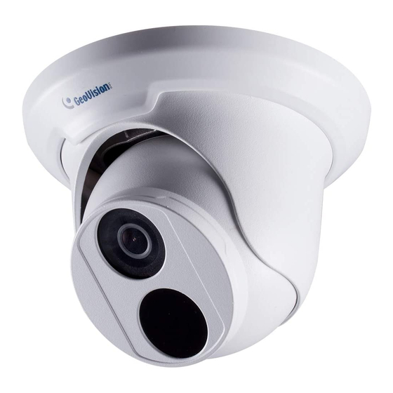
Page 8: Overview
Introduction 1.3 Overview Description Bottom ring Housing Lens Infrared indicator Power connector (DC 12 V) An optional power adapter is required. Ethernet connector / PoE... -
Page 9: Installation
The Target Eyeball Dome is designed for outdoors. With the standard package, you can install the camera on the ceiling. Or you can purchase optional mounting accessories to mount GV-EBD4700 on a wall. Below are the instructions for Ceiling Mount. There are two kinds of Ceiling Mount: Concealed Installation and Open Installation. - Page 10 Installation Remove the bottom ring by turning it anticlockwise. Connect the cables and then secure the camera. Adjust the monitoring direction.
- Page 11 Lead the cables out from the open slot on the bottom ring before screwing the camera to the ceiling as shown in step 4 in For Concealed Installation. Note: You can optionally purchase GV-Mount211 for Wall Bracket Mount. For details, see GV-EBD4700 IR Eyeball IP Dome User’s Manual.
-
Page 12: Waterproofing The Cable
Connecting the Camera 3. Waterproofing the Cable Waterproof the Ethernet cable by using the supplied waterproof rubber set. Attach the seal ring to the RJ-45 plug. Seal ring Insert the waterproof components through the Ethernet cable as shown below. 2 Insert in order Insert the cylindrical waterproof ring into waterproof bolt. - Page 13 Insert the cable into the RJ-45 plug and screw the waterproof bolt in. Screw in the waterproof bolt lid. Bolt lid Finish the waterproof Installation.
-
Page 14: Accessing The Camera
Accessing the Camera 4. Accessing the Camera 4.1 System Requirements Once installed, your camera is accessible over the network. Make sure your PC has good network connection, and meet the following requirement: Intel Core i5-4670, 3.40 GHz Memory DDR3 8 GB RAM On Board Graphics Intel HD Graphics 4600 (Versions of driver from year 2014 or later required) -
Page 15: Looking Up The Dynamic Ip Address
Note: The computer you use to configure the IP address must be under the same LAN with your camera. 1. Download and install the GV-IP Device Utility program from http://www.geovision.com.tw/english/5_8.asp 2. On the GV-IP Utility window, click the button to search for the IP devices connected in the same LAN. - Page 16 Accessing the Camera 4. The login page appears. 5. For the first time accessing the Web interface, download and install the plug-in. 6. Type the default ID and password admin and click Apply to log in.
-
Page 17: Configuring The Ip Address
4.3 Configuring the IP Address If the camera is connected to LAN without a DHCP server, the default IP address will be 192.168.0.10. Follow the steps below to modify the IP address to avoid IP conflict with other GV-IP devices on the same LAN. 1. -
Page 18: The Web Interface
Upgrading System Firmware 5. The Web Interface Once you log in the Web interface, you will see the live view as shown below. No. Name Function Set the display ratio of the image. Scale: display images by 16:9. Proportional ... - Page 19 Reset the packet loss rate to zero. Display packet loss rate and bit rate information in the bottom. Note: The paths for saving snapshots and local recordings are set in System Configuration. The buttons (No. 9 and No. 10) will appear on the floating toolbar after you move the mouse cursor on a live view window.
-
Page 20: Upgrading System Firmware
Upgrading System Firmware 6. Upgrading System Firmware GeoVision periodically releases the updated firmware on the website. To load the new firmware into the camera, follow the instructions below. 1. At the top of the Web interface, click Setup. 2. In the left menu, select System and select Maintenance. This page appears. -
Page 21: Restoring To Factory Default
7. Restoring to Factory Default You can restore the camera to factory default settings using the Web interface. 1. At the top, click Setup. 2. In the left menu, select System and select Maintenance. 3. Under the Config Management section, click the Default button. Note: There is no default button on the camera.
Need help?
Do you have a question about the GV-EBD4700 and is the answer not in the manual?
Questions and answers