GeoVision GV-TDR Series User Manual
Hide thumbs
Also See for GV-TDR Series:
- User manual (249 pages) ,
- Quick start manual (77 pages) ,
- User manual (224 pages)
Table of Contents
Advertisement
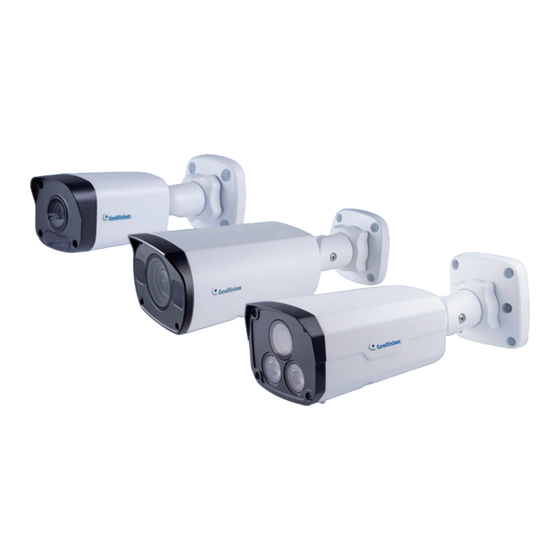
GV-IP Camera
GV-ABL / TBL Series
GV-ADR / TDR Series
GV-AVD / TVD Series
GV-BLFC5800
GV-EBD Series
GV-EBFC5800
GV-FER5702
GV-PTZ5810-IR
GV-TFD Series
Before attempting to connect or operate this product,
please read these instructions carefully and save this manual for future use.
User's Manual
UBN-UM-Z
Advertisement
Table of Contents


Need help?
Do you have a question about the GV-TDR Series and is the answer not in the manual?
Questions and answers