Table of Contents
Advertisement
Quick Links
Advertisement
Table of Contents

Subscribe to Our Youtube Channel
Related Manuals for HIKVISION UD03451B


Summary of Contents for HIKVISION UD03451B
-
Page 1: User Manual
Smart Camera User Manual Smart Camera User Manual UD03451B... - Page 2 Any and all information, including, among others, wordings, pictures, graphs are the properties of Hangzhou Hikvision Digital Technology Co., Ltd. or its subsidiaries (hereinafter referred to be “Hikvision”). This user manual (hereinafter referred to be “the Manual”) cannot be reproduced, changed, translated, or distributed, partially or wholly, by any means, without the prior written permission of Hikvision.
- Page 3 OF SUCH DAMAGES. REGARDING TO THE PRODUCT WITH INTERNET ACCESS, THE USE OF PRODUCT SHALL BE WHOLLY AT YOUR OWN RISKS. HIKVISION SHALL NOT TAKE ANY RESPONSIBILITES FOR ABNORMAL OPERATION, PRIVACY LEAKAGE OR OTHER DAMAGES RESULTING FROM CYBER ATTACK, HACKER ATTACK, VIRUS INSPECTION, OR OTHER INTERNET SECURITY RISKS;...
- Page 4 Smart Camera User Manual 2012/19/EU (WEEE directive): Products marked with this symbol cannot be disposed of as unsorted municipal waste in the European Union. For proper recycling, return this product to your local supplier upon the purchase of equivalent new equipment, or dispose of it at designated collection points. For more information see: www.recyclethis.info.
- Page 5 Smart Camera User Manual Cautions: Make sure the power supply voltage is correct before using the camera. Do not drop the camera or subject it to physical shock. Do not touch sensor modules with fingers. If cleaning is necessary, use a clean cloth with a bit of ethanol and wipe it gently.
-
Page 6: Table Of Contents
Smart Camera User Manual Table of Contents Chapter 1 Overview ......................... 8 Introduction ............................ 8 Main Features ..........................8 Specifications ..........................9 1.3.1 MV-SI622-00GM/MV-SI622-01GM Specification ..................9 1.3.2 MV-SI622-00GM/MV-SI622-01GM Response Curve ................. 10 Camera Physical Interfaces ......................10 1.4.1 Camera Structure ............................10 1.4.2 Camera Dimension ............................ - Page 7 Smart Camera User Manual 3.3.3 ROI Settings ..............................31 3.3.4 Exposure Time ..............................32 3.3.5 Gain Control ..............................33 3.3.6 Gamma Correction ............................34 3.3.7 Brightness ............................... 35 3.3.8 Image Reverse ..............................35 3.3.9 Test Pattern..............................35 Light Source Control ........................37 Trigger and IO Control ........................
-
Page 8: Chapter 1 Overview
Smart Camera User Manual Chapter 1 Overview 1.1 Introduction The smart camera adopts aviation plug to RJ45 interface to perform real-time transmission of uncompressed or compressed image through a gigabit Ethernet interface. Remote image capturing and camera control, for example, the operating mode and the image parameters adjustment, are supported by client software. -
Page 9: Specifications
Smart Camera User Manual 1.3 Specifications 1.3.1 MV-SI622-00GM/MV-SI622-01GM Specification Table 1. 1 MV-SI622-00GM/MV-SI622-01GM Specification Model MV-SI622-00GM MV-SI622-01GM Parameters 5 MP 1" CMOS Smart Camera Camera Sensor Type 1" global shutter CMOS Resolution 2592 × 2048 4.8 μm × 4.8μm Pixel Size Frame Rate 30fps Dynamic Range... -
Page 10: Mv-Si622-00Gm/Mv-Si622-01Gm Response Curve
Smart Camera User Manual Light Source No light source With light source No lens waterproof shield With lens waterproof shield Control Client Smart MVS Protection Level IP67(with the lens shield) Certifications CE, FCC, and RoHS 1.3.2 MV-SI622-00GM/MV-SI622-01GM Response Curve Figure 1. 2 MV-SI622-00GM/MV-SI622-01GM Response Curve The response curve data is provided by the chip manufacture. -
Page 11: Camera Dimension
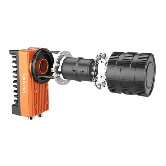
Smart Camera User Manual Figure 1. 3 Smart camera Structure 1.4.2 Camera Dimension The figure below shows the dimension of the smart camera without light source and camera housing. The camera should be installed with M4 screws from the package (supplied). Screw holes are in the each front panel and rear panel of the camera, each panel can be used to fix the camera to the bracket. -
Page 12: Interfaces Introduction
Smart Camera User Manual The camera adopts the C-Mount lens interface. 1.4.3 Interfaces Introduction The figure below shows the interfaces of the smart camera with light source and camera housing, including aviation plug to RJ45 network interface, 12-pin power and I/O interface, and 5-pin external light source interface. -
Page 13: External Light Source Interfaces
Smart Camera User Manual Figure 1. 6 Power and I/O Interface Table 1. 3 Description No. Signal Color I/O Type Description DC-PWR White DC 12V + Brown Power Grounding OPTO_OUT0 Green Output I/O Output 0 OPTO_OUT1 Yellow Output I/O Output 1 OPTO_OUT2 Grey Output... -
Page 14: Installation Accessories
Smart Camera User Manual Table 1. 4 Description No. Signal Color I/O Type Description LED+ Brown Output LED + LED- White Output LED - Blue Output Power Grounding OPTO_PWM Black Output light-coupled Isolation Trigger Signal OPTO_GND Grey Output light-coupled Isolation Grounding 1.4.6 Installation Accessories Prepare the installation accessories listed below before you install the smart camera. -
Page 15: Chapter 2 Camera Installation And Configuration
Chapter 2 Camera Installation and Configuration 2.1 Installing the Camera Steps: 1. Unpack the camera package, rotate the water-proof lens case anticlockwise, and take out the lamp cup. 2. Install the lens to the camera body by rotating the lens clockwise. 3. - Page 16 Smart Camera User Manual Figure 2. 2 Type I Installation 安装方式二示意图 Figure 2. 3 Type II Installation...
- Page 17 Smart Camera User Manual 安装方式三示意图 Figure 2. 4 Type III Installation 5. Use 8-pin avigation plug to RJ 45 network interface to connect the camera to a switch or a network card.. Figure 2. 5 Connect Network Cable 6. Use the supplied cable with a 12-pin power and I/O interface to connect the camera to a 24 V DC power adapter.
- Page 18 Smart Camera User Manual 7. If external light source is required, connect the camera to an external light source. Figure 2. 7 Connect the External Light Source Use 10 V DC to 30 V DC without using light source, and otherwise use 20 V DC to 30 V .
-
Page 19: Client Installation
Smart Camera User Manual 2.2 Client Installation Windows XP /7/8 32/64bit is a requirement. Visit www. hikvision. com to get more information. The client software is integrating all hardware drivers. Steps: 1. Get the client from the www. hikvision. com. - Page 20 Smart Camera User Manual Figure 2. 9 Install the Program 4. Click Install to start the installation, and click Finish to complete the installation. Figure 2. 10 Finish the Installation...
-
Page 21: Camera Configuration
Smart Camera User Manual 2.3 Camera Configuration Guarantee the camera IP and your PC IP are under the same network segment. 2.3.1 Viewing Camera IP Address The default smart camera IP address is auto finding IP. Step: 1. Double click to enter the main interface. - Page 22 Smart Camera User Manual Figure 2. 12 Local Network Connection 2. Select Internet Protocol Version 4 (TCP/IPv4),and click Properties Figure 2. 13 Select Internet Protocol Version 4 (TCP/IPv4) 3. Check the radio button of Obtain an IP address automatically. 4. (Optional) You can also select Use the following IP address, and set the IP address which is under the same network segment with the camera.
-
Page 23: Setting Via Attribute Tree
Smart Camera User Manual Figure 2. 14 Local Network Connection Settings 6. You also need to enable the jumbo frame of the NIC. For different operating systems, the path to setting the jumbo frame may be different. Here we take Windows 7 as an example. - Page 24 Smart Camera User Manual 1. Double click the Smart MVS icon to enter the client software. The main user interface and the description of the client software are shown in Figure 2. 15 and Table 2. 1. Figure 2. 15 Main User Interface of the Client Software Table 2.
- Page 25 Smart Camera User Manual User Level Area Switches the user level quickly as beginner, expert, or guru. For details, refer to the User Manual of Smart MVS Control Client. Double click the camera on the device list in Devices and Attributes Tree area. Click the Attributes tab to enter the camera attribute page.
- Page 26 Smart Camera User Manual Device Control: In the Device Control attribute, you can view the camera details include device type, version, manufacturer details, device user ID, device reset, device temperature, etc. You can modify the device user ID and reset the device. ...
- Page 27 Smart Camera User Manual Figure 2. 17 Live View Interface You are recommended to save the settings, after the attributes has been edited so as to avoid that the settings are back to the default sate after reboot. Save Settings:Select one type from the User Set Selector dropdown list and click Execute of User Set Save to save the settings.
-
Page 28: Chapter 3 Functions
Smart Camera User Manual Chapter 3 Functions 3.1 Device Control Run the client software and click Device Control from the Attribute list. You will see the device manufacture, the model name, the device version, and so on. Input the device name in the textfiled of Device User ID, click the button Execute to reset the device, and check the sensor temperature shown in Figure 3.1. -
Page 29: Running Mode
Smart Camera User Manual Figure 3. 2 Setting Reading Mode 3.2.3 Running Mode The camera supports two running modes, normal and test. The client output the image and code in real time under the test mode. Under the normal mode, only the code is recognized, then the image and the code can be output. -
Page 30: Multi Frames Combine
Smart Camera User Manual as to display number only. Figure 3. 4 Setting Code Parameters 3.2.5 Multi Frames Combine The purpose of multi frames combine is raising accuracy of recognition barcode via disposing and combining multi frames image. Only the object moving is dynamic, multi frames combine is enable. -
Page 31: Image Setting
Smart Camera User Manual Image Setting Click Image Setting from the Attributes list. 3.3.1 Camera Data Format The camera supports Mono8 format which can be set from the dropdown list of Pixel Format. Figure 3. 6 Pixel Format 3.3.2 Acquisition Frame Rate Frame rate can be set in the Acquisition Frame Rate box, but the value of acquisition frame rate you set cannot be more than the frame rate supported by the camera itself. -
Page 32: Exposure Time
Smart Camera User Manual The camera can output ROI images depending on your requirements. ROI setting can decrease the data transmission bandwidth and increase the camera frame rate. The frame rates decrease while exposure time increasing, so the max exposure time should be less than the reciprocal of frame rate. -
Page 33: Gain Control
Smart Camera User Manual single mode or continuous mode, the exposure time will be limited to Auto Exposure Time Lower Limit and Auto Exposure Time Upper Limit. The time range should only be set between Auto Exposure Time Lower Limit and Auto Exposure Time Upper Limit. -
Page 34: Gamma Correction
Smart Camera User Manual Figure 3. 10 Gain Control The noise increases when Gain increases. Auto exposure and auto gain are mutually restricted. When the image is dark, the camera will firstly increase the exposure time. Secondly, the camera starts to adjust gain value when the exposure time turns to the maximum. -
Page 35: Brightness
Smart Camera User Manual Figure 3. 11 Gamma Curve Click Image Settings from the Attribute list. Select Gamma and set the value as shown in Figure 3.12. Figure 3. 12 Gamma Settings Different cameras models have different default function parameters. The figure shown above is only for reference. - Page 36 Smart Camera User Manual The default test pattern is off, shown as the figure 3.15. Figure 3. 15 Test Patten The camera provides four test patterns, including Mono Bar, Vertical Color Bar, Horizontal Color Bar, and Checkboard as shown in the following three figures. Color camera, and mono camera have different test patterns.
-
Page 37: Light Source Control
Smart Camera User Manual Figure 3. 17 Checkboard Test Pattern Figure 3. 18 Rolling Oblique White & Black Strip Test Pattern Light Source Control MV-SI622-01GM is the model with light source and lens case, which can control the light source by Smart MVS client. Click Light Source Control from the Attribute list. -
Page 38: Trigger And Io Control
Smart Camera User Manual Figure 3. 19 Light Source Control Trigger and IO Control 3.5.1 Trigger Mode The camera support internal and external trigger modes. The camera can output one image or several images continuously under the internal trigger mode. External trigger mode includes software trigger mode, hardware external trigger mode. - Page 39 Smart Camera User Manual Select LineIn0, LineIn1, or LineIn2 from the dropdown list of Trigger In Source to switch to the hardware external trigger status. Following parameter settings of input signal for hardware external trigger: 1) Trigger Edge Selection Rising Edge/Falling Edge, and High Level/Low Level are available. 2) Trigger Delay As shown in Figure 3.22(Rising Edge is the trigger signal), the camera can set delay time when receiving the trigger signal.
- Page 40 Smart Camera User Manual Trigger_in1 Trigger_in2 Trigger_in3 Before debounce Trigger_in2 Trigger_in3 After debounce Debouncer Time Debouncer Time Figure 3. 23 The Debounce of Triggering Input Signal Sequence Map 4) Burst mode The camera supports burst mode: receiving one trigger signal and outputting multiply frames images.
-
Page 41: Opto-Isolated Output
Smart Camera User Manual division. Click Trigger and IO Control and select LineIn_0 from the Count Source, and enter the available value in count number, ranging from 1 to 1023. Figure 3. 26 Counter Frequency Division Configuration 3.5.2 Opto-isolated output Click Line Out Selector as the following figure, the signals form LineOut 0, LineOut 1, LineOut 2 are transmission via 12 Pin I/O cable, PWM1 is transmitted by externa light cable, which control the external light. -
Page 42: Opto-Isolated Input/Output Circuit
Smart Camera User Manual HardTriggerActive: hardware trigger mode SoftTrigger: software trigger mode Figure 3. 28 Opto-isolated output event source The output delay time can be set in Line Out Delay, and you can set pulse duration time in Line Out Duration according you need. When Line Out Activation Event box is Exposure Start Active, there will be an addition Flash Ahead Time in attribute tree which means the time before exposure. -
Page 43: Communication Control
Smart Camera User Manual 内部电源 IN0/IN1/IN2 内部逻辑 IN_COM Figure 3. 30 I/O input circuit (2) I/O output circuit: (the voltage is 5~30v, current is limited 200 mA) If output device signal is NPN, the device power negative is connected to the OUT_COM and the signal is connected to the OUT0/OUT1/OUT2, otherwise, reversal the cable. -
Page 44: Communication Protocol
Smart Camera User Manual Figure 3. 32 Communication Control Settings 3.6.2 Communication Protocol The camera supports three data communication protocols, smart SDK, TCP/IP, and Serial. Smart SDK: Transmit data throng SDK. TCP/IP: You are required to set the destination IP address and port, when adopting TCP/IP. -
Page 45: User Set Control
Smart Camera User Manual When adopting TCP/IP or Serial to transmit the data, you are required to set parameters shown in the figure below. Figure 3. 35 Data Format Settings User Set Control Click User Set Control from the Attribute list. 3.8.1 Parameters Saving and Loading The camera can save four groups of parameters, including one group of factory parameter and three groups of configurable parameter. -
Page 46: User Led Indicator
Smart Camera User Manual keyboard to validate the settings. Figure 3. 36 Parameters Saving and Loading Load Save Load Figure 3. 37 The Relationship Among Four Groups of Parameters 3.8.2 User LED Indicator The camera supports User LED Indicators, User LED 1, and User LED 2. You are able to judge whether the camera is running normally or not by LED indicators. -
Page 47: Arithmetic Control
Smart Camera User Manual Figure 3. 38 User LED Indicator Settings Off: Disable the function. Find Barcode: The LED indicator flashes once when finding a code. Who am I: Used to help you judge which camera is operating. LED indicator flashes once for the operating camera. - Page 48 Smart Camera User Manual Common parameter is bellowing: Code Number: the max number could be recognized in one frame Filter Size: the size of oriented windows used to initially location Waiting Time: the max time used to recognition on frame image ...
-
Page 49: Chapter 4 Troubleshooting
Smart Camera User Manual Chapter 4 Troubleshooting Indicator Introduce There are five LED indicators in the camera, power indicator, network linkage indicator, network transmission indicator, user indicator 1, and user indicator 2, shown as the figure below. Figure 4. 1 Camera Indicator Table 4. -
Page 50: Indicator Status Description
Smart Camera User Manual Indicator Status Description Table 4. 3 LED Status Description Camera Power Network Network User User Sulution Status Indicator Linkage in Transmissio Indicator Indicator in Blue Green n in Yellow 1 in Blue 2 in Blue (PWR) (LNK) (ACT) (U1) -
Page 51: Faq
Smart Camera User Manual Table 4. 4 FAQ Problem Possible Reasons Solutions Description 1. The camera cannot be detected 1. The camera does not by the client Confirm that the power supply of camera work properly. software. is well connected (via LED indicators), 2. - Page 52 Smart Camera User Manual...
Need help?
Do you have a question about the UD03451B and is the answer not in the manual?
Questions and answers