H3C WA2210-AG Installation Manual
Wlan wa2200 series
Hide thumbs
Also See for WA2210-AG:
- Fundamentals configuration manual (137 pages) ,
- Command reference manual (131 pages) ,
- Installation manual (45 pages)
Table of Contents
Advertisement
Quick Links
Download this manual
See also:
Configuration Manual
Advertisement
Chapters
Table of Contents

Related Manuals for H3C WA2210-AG


Summary of Contents for H3C WA2210-AG
- Page 1 H3C WA2200 Series WLAN Access Points Installation Manual Hangzhou H3C Technologies Co., Ltd. http://www.h3c.com Manual Version:...
- Page 2 Copyright © 2006-2007, Hangzhou H3C Technologies Co., Ltd. and its licensors All Rights Reserved No part of this manual may be reproduced or transmitted in any form or by any means without prior written consent of Hangzhou H3C Technologies Co., Ltd.
-
Page 3: About This Manual
About This Manual Related Documentation In addition to this manual, each H3C WA2200 Series WLAN Access Points documentation set includes the following: Manual Description H3C WA2200 Series WLAN Access Points Guides the user to configure features Operation Manual supported by the WA2200 series. - Page 4 Conventions The manual uses the following conventions: I. Command conventions Convention Description Boldface The keywords of a command line are in Boldface. italic Command arguments are in italic. Items (keywords or arguments) in square brackets [ ] are optional. Alternative items are grouped in braces and separated by { x | y | ...
- Page 5 III. Symbols Convention Description Means reader be extremely careful. Improper operation Warning may cause bodily injury. Means reader be careful. Improper operation may cause Caution data loss or damage to equipment. Note Means a complementary description. Environmental Protection This product has been designed to comply with the requirements on environmental protection.
-
Page 6: Table Of Contents
Installation Manual H3C WA2200 Series WLAN Access Points Table of Contents Table of Contents Chapter 1 Product Overview ......................1-1 1.1 Introduction ........................1-1 1.2 Hardware Configuration..................... 1-2 1.2.1 LEDs........................1-3 1.2.2 Interfaces......................... 1-7 Chapter 2 Installation Preparations..................... 2-1 2.1 Unpacking and Inspection ....................2-1 2.2 Preparing Installation Tools .................... - Page 7 Installation Manual H3C WA2200 Series WLAN Access Points Table of Contents 5.2 Setting Up a Software Debugging Environment ..............5-5 5.2.1 Setting Up a Connection with the AP Through the Console Interface ....5-5 5.2.2 Telneting to the AP....................5-5 5.2.3 Configuring Telnet....................
- Page 8 Figure 1-1 Positions of the WA2200 series on the network........... 1-1 Figure 1-2 Appearance of the WA2200 series ............... 1-2 Figure 1-3 LEDs on the H3C WA2210-AG/WA2220-AG ............1-3 Figure 1-4 LEDs on the H3C WA2220E-AG ................1-5 Figure 1-5 LEDs on the H3C WA2210X-G ................1-6 Figure 1-6 LEDs on the WA2220X-AG and WA2220X-AGP ..........
- Page 9 Installation Manual H3C WA2200 Series WLAN Access Points List of Figures Figure 4-12 Install an omni antenna on the AP directly ............4-5 Figure 4-13 Connect the Ethernet electrical interface to the uplink device ......4-5 Figure 4-14 Connect the Ethernet optical interface to the uplink device ....... 4-5 Figure 4-15 Exploded view of the port lightning protector (PoE) ...........
- Page 10 Table 1-1 Physical dimensions of the WA2200 series ............1-2 Table 1-2 Protocols that each model supports and the chassis material ....... 1-2 Table 1-3 Description of LEDs on the H3C WA2210-AG/WA2220-AG ........1-4 Table 1-4 Description of LEDs on the H3C WA2220E-AG............. 1-5 Table 1-5 Description of LEDs on the H3C WA2210X-G, WA2220X-AG, and WA2220X-AGP ............................
-
Page 11: Chapter 1 Product Overview
The H3C WA2200 series WLAN access points (hereinafter referred to as the WA2200 series) are developed by Hangzhou H3C Technologies Co., Ltd. (hereinafter referred to as H3C). The WA2200 series consist of six models of access points (APs), which fall into three types according to the application environment: indoor, enhanced, and outdoor. -
Page 12: Hardware Configuration
Installation Manual H3C WA2200 Series WLAN Access Points Chapter 1 Product Overview Figure 1-2 Appearance of the WA2200 series Table 1-1 Physical dimensions of the WA2200 series Model Physical dimensions (H×W×D) H3C WA2210-AG/WA2220-AG, (indoor) 40×166×118 mm (1.57×6.54×4.65 in.) H3C WA2220E-AG, (enhanced) 35×195×135 mm (1.38×7.68×5.31 in.) -
Page 13: Leds
1.2.1 LEDs The positions and identifications of LEDs on the panel vary with the models. For details about these LEDs, see Table 1-3, Table 1-4, and Table 1-5. I. H3C WA2210-AG/WA2220-AG Figure 1-3 LEDs on the H3C WA2210-AG/WA2220-AG... -
Page 14: Table 1-3 Description Of Leds On The H3C Wa2210-Ag/Wa2220-Ag
11b/g Green Flashing slowly: A wireless station is accessing the device. Flashing quickly: Data is being transmitted or received. Caution: The WA2210-AG is a single-RF device. The 11a and 11b/g LEDs cannot be on or flash at the same time. -
Page 15: Figure 1-4 Leds On The H3C Wa2220E-Ag
H3C WA2200 Series WLAN Access Points Chapter 1 Product Overview II. H3C WA2220E-AG Figure 1-4 LEDs on the H3C WA2220E-AG Table 1-4 Description of LEDs on the H3C WA2220E-AG Color Meaning Displays the power supply status: On: The power supply is normal.. -
Page 16: Figure 1-5 Leds On The H3C Wa2210X-G
On: The link on the Ethernet interface is up. LINK/ACT Green Off: The link on the Ethernet interface is down. Flashing: Data is being transmitted or received. III. H3C WA2210X-G, WA2220X-AG, and WA2220X-AGP Figure 1-5 LEDs on the H3C WA2210X-G Figure 1-6 LEDs on the WA2220X-AG and WA2220X-AGP... -
Page 17: Interfaces
Installation Manual H3C WA2200 Series WLAN Access Points Chapter 1 Product Overview Table 1-5 Description of LEDs on the H3C WA2210X-G, WA2220X-AG, and WA2220X-AGP Color Meaning Displays the power supply status: On: The power supply is normal.. POWER Green Off/flashing: The power supply is not connected or well connected or the device works abnormally. -
Page 18: Table 1-6 Descriptions Of Interfaces On Wa2200 Series Wlan Access Points
Installation Manual H3C WA2200 Series WLAN Access Points Chapter 1 Product Overview 2.4 GHz or/and 5 GHz antenna interface(s) Console interface Ethernet interface (optical and electrical) Power interface for indoor and enhanced models Note: In addition, the indoor and enhanced models have a reset button, a security slot, a grounding screw. - Page 19 Installation Manual H3C WA2200 Series WLAN Access Points Chapter 1 Product Overview Standards and Model Interface Description protocols This antenna interface is used to Antenna IEEE802.11a connect a 5-GHz antenna or a interface 2 feeder. The console interface is used for...
-
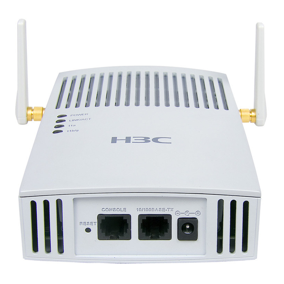
Page 20: Figure 1-7 Interfaces On H3C Wa2210-Ag/Wa2220-Ag(Indoor)
Figure 1-7 Interfaces on H3C WA2210-AG/WA2220-AG Caution: H3C WA2210-AG is a single-RF device. Viewed from the front, the antenna interface on the left (antenna interface 1 in Figure 1-7) is the main antenna interface, while the one on the right (antenna interface 2 in Figure 1-7) is the auxiliary antenna interface. -
Page 21: Figure 1-8 Interfaces On H3C Wa2220E-Ag(Enhanced)
Installation Manual H3C WA2200 Series WLAN Access Points Chapter 1 Product Overview II. Interfaces provided by H3C WA2220E-AG Figure 1-8 Interfaces on H3C WA2220E-AG III. Interfaces provided by H3C WA2210X-G/WA2220X-AG/WA2220X-AGP Figure 1-9 Interfaces on H3C WA2210X-G/WA2220X-AG/WA2220X-AGP 1-11... - Page 22 Installation Manual H3C WA2200 Series WLAN Access Points Chapter 1 Product Overview Note: H3C WA2210X-G is a single-RF device and provides no 5-GHz antenna interface. 1-12...
-
Page 23: Chapter 2 Installation Preparations
220 VAC power cord 1 PCS Console cable 1 PCS Installation kit 1 PCS Omni antenna 2 PCS H3C WA2200 Series WLAN Access Points Installation Manual 1 PCS H3C WA2200 Series WLAN Access Points Electronic 1 PCS Documentation Packing list 1 PCS Note: The accessories may vary with the models and are subject to the packing list. -
Page 24: Preparing Installation Tools
Installation Manual H3C WA2200 Series WLAN Access Points Chapter 2 Installation Preparations 2.2 Preparing Installation Tools When installing the AP, you may need the tools listed in Table 2-2. You should select the appropriate tools according to the installation environment. -
Page 25: Temperature And Humidity Requirements
Installation Manual H3C WA2200 Series WLAN Access Points Chapter 2 Installation Preparations 2.3.2 Temperature and Humidity Requirements Table 2-3 lists the operating temperature and humidity requirements. Table 2-3 Environment specifications Recommended Test Specification Range value condition Operating 0°C to 45°C (32°F to 25°C (77°F) -
Page 26: Grounding And Lightning Protection
Installation Manual H3C WA2200 Series WLAN Access Points Chapter 2 Installation Preparations Caution: If the voltage is unstable, a voltage regulator or stabilizer is required. An uninterrupted power supply (UPS) is required for uninterrupted communication. 2.3.4 Grounding and Lightning Protection... -
Page 27: Chapter 3 Installation Of Indoor Aps
Installation Manual H3C WA2200 Series WLAN Access Points Chapter 3 Installation of Indoor APs Chapter 3 Installation of Indoor APs You can directly place an indoor model (including the enhanced model) on a desk. The rubber feet on the bottom of the AP help you to place it horizontally. Or you can fix it onto a wall by using the wall-mounting bracket. -
Page 28: Installing The Ap
Installation Manual H3C WA2200 Series WLAN Access Points Chapter 3 Installation of Indoor APs 3.3 Installing the AP The following describes how to install the AP on a wall. Installing the Wall-Mounting Bracket on a Wall Installing the AP on the Wall-Mounting Bracket Locking the AP onto the Wall-Mounting Bracket (Optional) 3.3.1 Installing the Wall-Mounting Bracket on a Wall... -
Page 29: Installing The Ap On The Wall-Mounting Bracket
Installation Manual H3C WA2200 Series WLAN Access Points Chapter 3 Installation of Indoor APs Figure 3-3 Install the wall-mounting bracket 3.3.2 Installing the AP on the Wall-Mounting Bracket Follow these steps to install the AP on the wall-mounting bracket: Align the AP with the hooks on the wall-mounting bracket and hang the AP on the bracket (see (1) in Figure 3-4 and Figure 3-5). -
Page 30: Locking The Ap Onto The Wall-Mounting Bracket (Optional)
Installation Manual H3C WA2200 Series WLAN Access Points Chapter 3 Installation of Indoor APs Expansion screw Hock Figure 3-4 Fix the indoor AP onto the wall-mounting bracket Figure 3-5 Fix the enhanced AP onto the wall-mounting bracket 3.3.3 Locking the AP onto the Wall-Mounting Bracket (Optional) The indoor and enhanced APs have a security slot on the top, which can be used to lock the AP onto the wall-mounting bracket to prevent theft. -
Page 31: Figure 3-6 Lock The Indoor Ap Onto The Wall-Mounting Bracket
Installation Manual H3C WA2200 Series WLAN Access Points Chapter 3 Installation of Indoor APs Follow these steps to lock the AP onto the wall-mounting bracket: Insert the locking plate into the security slot on the top of the AP (see (1) in Figure 3-6 and Figure 3-7). -
Page 32: Connecting The Power Supply
Installation Manual H3C WA2200 Series WLAN Access Points Chapter 3 Installation of Indoor APs Locking plate Latch Locking hole Wall-mounting bracket Figure 3-7 Lock the enhanced AP onto the wall-mounting bracket Note: The lock is user supplied. 3.4 Connecting the Power Supply 3.4.1 Local Power Supply... -
Page 33: Power Over Ethernet
Installation Manual H3C WA2200 Series WLAN Access Points Chapter 3 Installation of Indoor APs Power interface Power adapter Figure 3-8 Local power supply connection 3.4.2 Power over Ethernet If the uplink device of the AP is a PoE-capable switch or the like, use an Ethernet cable to directly connect the Ethernet interface of the AP to the PoE-capable device. -
Page 34: Connecting The Network
Installation Manual H3C WA2200 Series WLAN Access Points Chapter 3 Installation of Indoor APs 3.5 Connecting the Network Connect the Ethernet interface of the AP to an Ethernet interface of the switch to implement Internet or MAN access, as shown in Figure 3-10. -
Page 35: Chapter 4 Installation Of Outdoor Aps
Chapter 4 Installation of Outdoor APs The outdoor models of the WA2200 series are H3C WA2210X-G, H3C WA2220X-AG, and H3C WA2220X-AGP. You can select an appropriate model according to the actual requirement. The three outdoor models are waterproof, dustproof, and lightningproof. -
Page 36: Figure 4-2 Installation Flowchart Of The Ap On A Wall
Installation Manual H3C WA2200 Series WLAN Access Points Chapter 4 Installation of Outdoor APs Start Mark Drill holes Install anchors Fix the wall- mounting bracket Fix the AP Figure 4-2 Installation flowchart of the AP on a wall Mark Step Operation Put the wall-mounting bracket on the installation position against the wall. -
Page 37: Figure 4-3 Wall-Mounting Bracket Structure And Positions Of Screw Holes
Installation Manual H3C WA2200 Series WLAN Access Points Chapter 4 Installation of Outdoor APs Figure 4-3 Wall-mounting bracket structure and positions of screw holes Drill holes Step Operation Use a percussion drill with a 6-mm (0.24-in) bit to drill holes on the three markings. - Page 38 Installation Manual H3C WA2200 Series WLAN Access Points Chapter 4 Installation of Outdoor APs Note: Before installation, remove dust inside and around all holes with a vacuum cleaner, and then measure the distances between holes. If there is a large error, mark and drill holes again.
-
Page 39: Figure 4-4 Install The Outdoor Ap On A Wall
Installation Manual H3C WA2200 Series WLAN Access Points Chapter 4 Installation of Outdoor APs Screw M10×12 Figure 4-4 Install the outdoor AP on a wall II. Installing the AP on a pole The fixing support for installing the outdoor AP on a pole consists of two major components: a pair of V-shaped brackets and a mounting plate. -
Page 40: Figure 4-5 Pole And Pole Base
Installation Manual H3C WA2200 Series WLAN Access Points Chapter 4 Installation of Outdoor APs Figure 4-5 Pole and pole base Fix the mounting plate onto one V-shaped fixing bracket with screws. Fix the pair of V-shaped fixing brackets on a vertical or horizontal pole with bolts, flat washers, spring washers, and nuts (see Figure 4-6 or Figure 4-7). -
Page 41: Installing An Outdoor Antenna
Installation Manual H3C WA2200 Series WLAN Access Points Chapter 4 Installation of Outdoor APs Bolt M10 nut #10 spring washer #10 flat washer V-shaped fixing bracket Mounting plate Figure 4-7 Install the outdoor AP on a horizontal pole Fix the AP onto the mounting plate with screws (see the dashed line and arrow in Figure 4-6 or Figure 4-7). -
Page 42: Figure 4-8 Install A Directional Outdoor Antenna On A Parapet
Installation Manual H3C WA2200 Series WLAN Access Points Chapter 4 Installation of Outdoor APs Follow these steps to install a pole on a parapet: Weld the lightning rod onto the tip of the pole. Install the pole on a parapet or cement pier. - Page 43 Installation Manual H3C WA2200 Series WLAN Access Points Chapter 4 Installation of Outdoor APs If there are parapets around the building top and the parapets are 1200 mm (47.24 in) high or higher, install the antenna pole on a parapet with expansion bolts and fix the directional outdoor antenna onto the pole with pole-mounting brackets (see the left diagram in Figure 4-8).
-
Page 44: Figure 4-10 Install Omni Antennas
Installation Manual H3C WA2200 Series WLAN Access Points Chapter 4 Installation of Outdoor APs 45° 45° Lightning protection angle Lightning rod Omni outdoor antenna Clamp Antenna pole Figure 4-10 Install omni antennas If the lightning rod cannot be installed on a separate pole owing to the environment limitation, the installation method shown in Figure 4-11 can be adopted. -
Page 45: Figure 4-11 Install An Omni Antenna Under A Special Environment
Installation Manual H3C WA2200 Series WLAN Access Points Chapter 4 Installation of Outdoor APs Lightning rod 45° Omni outdoor antenna >1000 mm 3000 mm Clamp Angle steel Antenna pole Figure 4-11 Install an omni antenna under a special environment Note: In Figure 4-11, the antenna pole is welded with two angle steels to the lightning rod pole, instead of a cement pier. -
Page 46: Connecting External Cables
Installation Manual H3C WA2200 Series WLAN Access Points Chapter 4 Installation of Outdoor APs Figure 4-12 Install an omni antenna on the AP directly Note: After the omni antenna is installed on the AP, the antenna should be at least one meter away from the pole or other metal objects. - Page 47 Installation Manual H3C WA2200 Series WLAN Access Points Chapter 4 Installation of Outdoor APs I. Connecting the RF cable The RF cable refers to the cable between the antenna interface and the antenna. Follow these steps to connect the RF cable: Screw one end of the feeder lightning arrester onto the antenna interface.
-
Page 48: Figure 4-13 Connect The Ethernet Electrical Interface To The Uplink Device
Installation Manual H3C WA2200 Series WLAN Access Points Chapter 4 Installation of Outdoor APs Outdoor Antenna RF coaxial Indoor LAN switch Ethernet Cable Port lightning protector power Grounding cable Power adaptor Figure 4-13 Connect the Ethernet electrical interface to the uplink device... -
Page 49: Figure 4-15 Exploded View Of The Port Lightning Protector (Poe)
Installation Manual H3C WA2200 Series WLAN Access Points Chapter 4 Installation of Outdoor APs Power (Surge) To Network To AP Ethernet cable Ethernet cable Grounding cable AC power(220V) Figure 4-15 Exploded view of the port lightning protector (PoE) Note: If the uplink device is a PoE switch, no port lightning protector or power adapter is required. -
Page 50: Figure 4-16 Ethernet Cable Connector
Installation Manual H3C WA2200 Series WLAN Access Points Chapter 4 Installation of Outdoor APs RJ-45 connector Figure 4-16 Ethernet cable connector Ethernet cables fall into straight-through Ethernet cables and crossover Ethernet cables. Straight-through Ethernet cable: The wires of a twisted pair cable are crimped in the same sequence in the RJ-45 connectors at both ends. -
Page 51: Table 4-2 Rj-45 Crossover Ethernet Cable Pinouts
Installation Manual H3C WA2200 Series WLAN Access Points Chapter 4 Installation of Outdoor APs Table 4-2 RJ-45 crossover Ethernet cable pinouts Pin of Pin of Category-5 twisted RJ-45 Signal Signal direction RJ-45 pair cable connector connector White (orange) Orange White (green) —... -
Page 52: Figure 4-17 Insert The Ethernet Cable Connector Into The Ethernet Interface
Installation Manual H3C WA2200 Series WLAN Access Points Chapter 4 Installation of Outdoor APs Ethernet connector Waterproof cover Sealing nut Joint between connector and cable Figure 4-17 Insert the Ethernet cable connector into the Ethernet interface First tighten the waterproof cover and then the sealing nut. -
Page 53: Powering On The Ap
Installation Manual H3C WA2200 Series WLAN Access Points Chapter 4 Installation of Outdoor APs Follow these steps to connect a fiber cable: Insert an SFP module into the Ethernet optical interface on the AP. Insert the LC connectors of two ZX fibers with a waterproof cover into the two optical interfaces on the SFP module. -
Page 54: Figure 4-19 Connection Of External Cables Of The Ap
Installation Manual H3C WA2200 Series WLAN Access Points Chapter 4 Installation of Outdoor APs Outdoor antenna RF cable Outdoor antenna Grounding cable for feeder lightning arrester Grounding cable Ethernet cable Fiber cable Figure 4-19 Connection of external cables of the AP... -
Page 55: Connecting The Network
Installation Manual H3C WA2200 Series WLAN Access Points Chapter 4 Installation of Outdoor APs 4.2 Connecting the Network In practice, the AP can be connected to the Internet or a MAN through an Ethernet interface, as shown in Figure 4-20. -
Page 56: Chapter 5 Software Setting
Installation Manual H3C WA2200 Series WLAN Access Points Chapter 5 Software Setting Chapter 5 Software Setting The WA2200 series can work in the FIT mode or FAT mode. When setting the AP, you must first determine its working mode. The software of the WA2200 series has been loaded and debugged before delivery. -
Page 57: Switching From The Fat Mode To The Fit Mode
Installation Manual H3C WA2200 Series WLAN Access Points Chapter 5 Software Setting 5.1.2 Switching from the FAT Mode to the FIT Mode Follow these steps to switch from the FAT mode to the FIT mode: Step Operation Connect one end of a serial cable to the serial interface on the maintenance... -
Page 58: Setting Up A Connection With The Ap Through The Console Interface
Installation Manual H3C WA2200 Series WLAN Access Points Chapter 5 Software Setting with an AC. This section only describes the software configuration for the AP working in the FAT mode. 5.2.1 Setting Up a Connection with the AP Through the Console Interface... -
Page 59: Configuring Telnet
Installation Manual H3C WA2200 Series WLAN Access Points Chapter 5 Software Setting Step Operation Run the Telnet program on the maintenance e terminal and enter the IP address of the AP to log in to the command line interface. By default, Telnet is disabled on the AP. Therefore, you need to enable Telnet on the AP and configure the IP address, login username, and password if you want to use Telnet. -
Page 60: Configuring A Fit Ap
Installation Manual H3C WA2200 Series WLAN Access Points Chapter 5 Software Setting 5.3 Configuring a FIT AP A FIT AP needs to cooperate with the AC and there is originally no configuration on the FIT AP. All configurations of the FIT AP are first performed on the AC and then sent to the FIT AP. -
Page 61: Configuring A Fit Ap On The Ac
Installation Manual H3C WA2200 Series WLAN Access Points Chapter 5 Software Setting II. Associating a FIT AP with the AC Follow these steps to associate a FIT AP with the AC: Step Operation Enter system view. <H3C>system-view System View: return to User View with Ctrl+Z. - Page 62 Installation Manual H3C WA2200 Series WLAN Access Points Chapter 5 Software Setting II. Configuring a service template Follow these steps to configure a service template: Step Operation Enter system view. <H3C>system-view System View: return to User View with Ctrl+Z. [H3C] Create a service template.
-
Page 63: Security Setting
Installation Manual H3C WA2200 Series WLAN Access Points Chapter 5 Software Setting IV. Binding the configurations to AP view Follow these steps to bind the configurations to AP view: Step Operation Enter system view. <H3C>system-view System View: return to User View with Ctrl+Z. -
Page 64: Configuring A Fat Ap
Installation Manual H3C WA2200 Series WLAN Access Points Chapter 5 Software Setting Step Operation Configure the TKIP encryption template. Configure an encryption template for SSID testwep104, with the encryption method being WEP104, key-id being 1, and key being 1234567980123. [H3C-wlan-st-22]ssid testwep104... -
Page 65: Setting A System Name And The System Clock
Installation Manual H3C WA2200 Series WLAN Access Points Chapter 5 Software Setting Step Operation Set the SSID. For example, set the SSID to testFatAP2. [H3C-wlan-st-2]ssid testFatAP2 [H3C-wlan-st-2] Enable the service template. [H3C-wlan-st-2]service-template enable [H3C-wlan-st-2] III. Configuring an RF interface (WLAN-radio) Bind the WLAN-BSS and service template to the specified RF interface. -
Page 66: Security Setting
Installation Manual H3C WA2200 Series WLAN Access Points Chapter 5 Software Setting Follow these steps to set a system name: Step Operation Enter system view. <H3C>system-view System View: return to User View with Ctrl+Z. [H3C] Use the sysname command to set a system name for the AP, for example, <H3C>system-view... - Page 67 Installation Manual H3C WA2200 Series WLAN Access Points Chapter 5 Software Setting II. Setting the encryption template Follow these steps to set the encryption template: Step Operation Enter system view. <H3C>system-view System View: return to User View with Ctrl+Z. [H3C] Enter service template view, for example, encryption template 3.
- Page 68 Compliance and Safety Manual WA 2200 series Wireless LAN Access Point Table of Contents Table of Contents Chapter 1 Regulatory Compliance Information......1-1 1.1 Regulatory compliance standards........1-1 1.2 European Regulatory compliance........1-2 1.2.1 EU Compliance information........1-2 1.2.2 EU Country Restriction in 2.4GHz band....1-3 1.2.3 EU Country Restriction in 5GHz band.....1-4 1.3 USA regulatory compliance ..........1-5 1.3.1 FCC Part 15.............1-5...
-
Page 69: List Of Figures
Compliance and Safety Manual WA 2110-AG Wireless LAN Access Point List of Tables List of Figures Error! No table of figures entries found. List of Tables Table 2-1 Regulatory compliance standards ......1-1... -
Page 70: Chapter 1 Regulatory Compliance Information
Compliance and Safety Manual WA 2200 series Wireless LAN Chapter 1 Regulatory Compliance Access Point Information Chapter 1 Regulatory Compliance Information 1.1 Regulatory compliance standards Table 1-1 Regulatory compliance standards Discipline Standards FCC Bulletin OET-65C FCC Part 15.207 & 15.209 & 15.247 FCC Part 15.207 &... -
Page 71: European Regulatory Compliance
Compliance and Safety Manual WA 2200 series Wireless LAN Chapter 1 Regulatory Compliance Access Point Information Discipline Standards UL 60950-1:2003 CAN/CSA C22.2 No 60950-1-03 Safety IEC 60950-1:2001 EN 60950-1/A11:2004 EN 50385 1.2 European Regulatory compliance WA 2200 Series Wireless LAN Access Point complies with the following European Directives: R&TTE Directive 1999/5/EC. -
Page 72: Eu Country Restriction In 2.4Ghz Band
Select the country in which the product is installed to ensure product operation is in compliance with local regulations. For information on how to select the country, refer to the “Wireless Configuration Command” module in H3C Wireless Control Manager Command Manual. Intended use: IEEE 802.11 a/b/g radio LAN device. -
Page 73: Eu Country Restriction In 5Ghz Band
Compliance and Safety Manual WA 2200 series Wireless LAN Chapter 1 Regulatory Compliance Access Point Information 1.2.3 EU Country Restriction in 5GHz band The frequency band 5150-5250MHz can not be used outdoors. This device support DFS function. Austria Only the frequency band 5150-5250MHz is allowed. France The frequency band 5470-5750MHz is not allowed. -
Page 74: Usa Regulatory Compliance
Compliance and Safety Manual WA 2200 series Wireless LAN Chapter 1 Regulatory Compliance Access Point Information 1.3 USA regulatory compliance 1.3.1 FCC Part 15 I. US Federal Communications Commission (FCC) EMC Compliance This equipment has been tested and found to comply with the limits for a class B digital device, pursuant to part 15 of the FCC Rules. - Page 75 Compliance and Safety Manual WA 2200 series Wireless LAN Chapter 1 Regulatory Compliance Access Point Information To ensure compliance with the requirements of FCC RF exposure, a minimum body to antenna distance of 20cm (8 inch) must be maintained when the device is operated. RF Frequency Requirements This equipment complies with FCC RF radiation exposure limits set forth for an uncontrolled environment.
- Page 76 Compliance and Safety Manual WA 2200 series Wireless LAN Chapter 1 Regulatory Compliance Access Point Information (15.21) Warning: Changes or modifications to this unit not expressly approved by the party responsible for compliance could void the user authority to operate the equipment. 15.19 (a)(3) This device complies with Part 15 of the FCC Rules.
-
Page 77: Chapter 2 Safety Information Sicherheitsinformationen 安全信息2-1
Compliance and Safety Manual Chapter 2 Safety Information WA 2110-AG Wireless LAN Access Sicherheitsinformationen 安全信息 Point Chapter 2 Safety Information Sicherheitsinformationen 安全信息 2.1 General Requirements Allgemeine Anforderungen通用要求 In order to reduce the technically unavoidable residual risk to a minimum, it is imperative to follow the rules below: Um das technisch bedingte Restrisiko auf ein Minimum zu begrenzen, ist es unbedingt erforderlich, die folgenden Regeln zu beachten:... -
Page 78: Electricity Safety Elektrische Sicherheit 用电安全
Compliance and Safety Manual Chapter 2 Safety Information WA 2110-AG Wireless LAN Access Sicherheitsinformationen 安全信息 Point 设备在工作时必须确保通风口的畅通,确保设备离墙壁或是 其它的可能堵塞通风口的物体的间距至少 5cm。 For AC supplied model: To ensure the safety of the equipment and human body, please unplug the AC power connector and do not use the fixed terminal in the lightning weather. - Page 79 Compliance and Safety Manual Chapter 2 Safety Information WA 2110-AG Wireless LAN Access Sicherheitsinformationen 安全信息 Point Sollte sich Wasser im Baugruppenträger befinden oder der Baugruppenträger feucht sein, ist die Energiezufuhr sofort zu unterbrechen und das System abzuschalten. 当有液体进入机架或机架有损坏时,请立即切断电源。 When operation is performed in a damp environment, make sure that water is kept off the equipment.
Need help?
Do you have a question about the WA2210-AG and is the answer not in the manual?
Questions and answers