
Related Manuals for H3C WA2620i-AGN


Summary of Contents for H3C WA2620i-AGN
- Page 1 H3C WA2620i-AGN Access Point Installation Guide Hangzhou H3C Technologies Co., Ltd. http://www.h3c.com Document version: 6PW102-20130712...
- Page 2 Copyright © 2011-2013, Hangzhou H3C Technologies Co., Ltd. and its licensors All rights reserved No part of this manual may be reproduced or transmitted in any form or by any means without prior written consent of Hangzhou H3C Technologies Co., Ltd. Trademarks H3C,...
- Page 3 Preface The H3C WA2620i-AGN AP Installation Guide describes the hardware specifications, preparations before installation, installation procedure, cabling and grounding, and login procedure of the WA2620i-AGN AP. This preface includes: Audience • Conventions • Obtaining documentation • Technical support • Documentation feedback •...
- Page 4 An alert that contains additional or supplementary NOTE information. Obtaining documentation You can access the most up-to-date H3C product documentation on the World Wide Web at http://www.h3c.com. Click the links on the top navigation bar to obtain different categories of product documentation: [Technical Support &...
- Page 5 Documentation feedback You can e-mail your comments about product documentation to info@h3c.com. We appreciate your comments.
-
Page 6: Table Of Contents
Contents Product overview ······························································································ 1 Preparing for installation ·················································································· 3 Safety recommendations ················································································· 3 Accessories provided with the AP ·································································· 3 User-supplied installation tools and equipment ············································· 4 Installing the AP ································································································ 6 Check before installation················································································· 7 ... -
Page 7: Product Overview
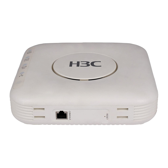
Product overview The H3C WA2620i-AGN Access Point has integrated antennas, and also supports external antennas. The WA2620i-AGN can serve as a fit AP to cooperate with wireless switches or access controllers to provide wireless access for WLAN users. All configuration tasks are configured on the wireless switches or access controllers. - Page 8 Figure 2 Deployment of the AP on hotspots (fat AP) Auditorium WA2620i-AGN Switch Core equipment room RADIUS Restaurant or server Switch WA2620i-AGN tea house Switch Wireless Parking lot WA2620i-AGN Switch Hall or WA2620i-AGN information desk Switch Table 1 Basic configuration Dimensions Max.
-
Page 9: Preparing For Installation
Preparing for installation Safety recommendations WARNING! Only qualified personnel can install and remove a WA2620i-AGN and its accessories. You must read all safety instructions supplied with the access points before installation and operation. To avoid possible bodily injury and equipment damage, read the following safety recommendations before you install a WA2620i-AGN. -
Page 10: User-Supplied Installation Tools And Equipment
Hex-head bolt, washer, and nut Rubber feet NOTE: Antennas, power adapter, and power cable are user-supplied. User-supplied installation tools and equipment When you install a WA2620i-AGN access point, you may need the following tools: Level Marker Knife Percussion drill with... - Page 11 Rubber hammer Phillips screwdriver Ladder...
-
Page 12: Installing The Ap
Installing the AP CAUTION: The WA2620i-AGN is usually installed on a high position, such as a wall or ceiling, so the maintenance personnel cannot log in from the console port to maintain and debug the AP. H3C recommends that you log in to... -
Page 13: Check Before Installation
“Appendix LEDs and ports.” Check that cabling has been completed. • The WA2620i-AGN supports 802.3af-compliant PoE. To achieve the best • performance, H3C recommends that you adopt GE connection to the power device. Record the MAC address and serial number of the AP (marked on the •... -
Page 14: Installing The Ap
Mounting the AP on a table WARNING! Do not place the WA2620i-AGN on any metal surface. Place it on a place where there are no obstacles and good signal strength is available. Attach the rubber feet supplied with the AP to the rear of the AP. -
Page 15: Mounting The Ap On A Wall
Figure 5 Mounting the AP on the table Mounting the AP on a wall To mount the AP on a wall, you need a wall-mounting bracket and wall anchor kit. Figure 6 Screw hole locations and sizes (in mm) Ø5.0 86.0 136.0 (1) Hook... - Page 16 To mount the AP on a wall: Use the wall-mounting bracket as a template to mark the locations of the mounting holes on the bracket. Drill three 5 mm (0.2 in) diameter holes on the marked mounting hole locations. Figure 7 Drilling holes in the wall 40 mm 86 mm Insert a wall anchor into each mounting hole, and tap the wall anchor...
- Page 17 Figure 8 Inserting a wall anchor Align the holes in the wall-mounting bracket with the anchors and insert screws through the installation holes into the wall anchors. Adjust the position of the wall-mounting bracket and tighten the screws. Figure 9 Installing the wall-mounting bracket (1) Wall-mounting bracket (2) Hook (3) Clip...
-
Page 18: Mounting The Ap On A Ceiling
Mount the AP on the hook on the wall-mounting bracket. See callout 1 Figure Pull down the AP with force until it clicks into place. See callout 2 Figure Figure 10 Fix the AP onto the wall-mounting bracket Mounting the AP on a ceiling NOTE: The ceiling tiles must be less than 18 mm (0.71 in) thick, and the ceiling •... - Page 19 Figure 11 Bolt holes on the wall-mounting bracket (in mm) (1) through (3) Bolt holes To install the AP on a ceiling: Drill two 5.0 mm (0.20 in) diameter holes in the ceiling where you want to mount the AP. The distance between the two holes must be the same as the distance between the two bolt holes on the mounting bracket.
-
Page 20: Connecting The Power Supply
Check that the AP is secured to the mounting bracket to avoid falloff. Connecting the power supply The WA2620i-AGN can be powered through PoE or a power adaptor. You can select either method as needed. Before connecting the power supply, check that the power supply is steady. -
Page 21: Local Power Supply
Output +48V at 0.52 A The WA2620i-AGN supports both AC and DC power adapters. You can connect the power port of the AP to the power source through a power adapter to supply power to the AP. Figure 13 Local power supply connection... -
Page 22: Poe Power Supply
PoE power supply CAUTION: When you apply 802.3af PoE power supply, connect one end of the • network cable to the network port on the AP, and the other end to an Ethernet port on a PoE-capable device (for example, a PoE-capable Ethernet switch). -
Page 23: Checking The Network Connection For The Fit Ap
AP Name State Model Serial-ID -------------------------------------------------------- WA2620i-AGN 219801A0CNC118000435 -------------------------------------------------------- Checking the network connection for the fat AP When the AP operates as a fat AP, use the ping command to ping the uplink network. If the network can be pinged successfully, the AP is successfully... -
Page 24: Logging In To The Fat Ap
AP to configure related settings before you install the AP. When the WA2620i-AGN operates as a fat AP, you can log in to the AP through the console port, or through Telnet or web to configure the AP, but you must obtain the IP address of the AP first. -
Page 25: Setting Up The Configuration Environment
Setting up the configuration environment NOTE: The serial ports on PCs do not support hot swapping. If the AP has been powered on, connect the console cable to the PC before connecting to the AP, and when you disconnect the cable, first disconnect from the AP. To connect the console cable: Plug the DB-9 female connector to the serial port of the PC. - Page 26 Figure 16 Connection description Select the serial port to be used from the Connect using list, and click OK.
- Page 27 Figure 17 Set the serial port used by the HyperTerminal connection Set Bits per second to 9600, Data bits to 8, Parity to None, Stop bits to 1, and Flow control to None, and click OK.
- Page 28 Figure 18 Set the serial port parameters NOTE: To restore the default settings, click Restore Defaults. The HyperTerminal window appears.
-
Page 29: Logging In Through The Console Port
Figure 19 HyperTerminal window Logging in through the console port Power on the AP, and you can see the following information: System is starting... Booting Normal Extend BootWare. … System application is starting... Startup configuration file does not exist. User interface con0 is available. Press ENTER to get started. - Page 30 Username—admin • Password—h3capadmin • Management IP address of VLAN-interface 1 of the AP—192.168.0.50, • with the subnet mask 255.255.255.0. If the default IP address is changed, contact the administrator to get the new IP address, or use the display vlan 1 command to view the IP address after logging in to the AP from the console port.
-
Page 31: Appendix Leds And Ports
Appendix LEDs and ports LEDs Table 3 describes the LEDs provided by the WA2620i-AGN. Table 3 LED description Mark Color Status Description The AP is booting. NOTE: When the AP operates as a Flashing at 1 Hz fit AP, it is always in this... -
Page 32: Ports
The WA2620i-GN provides the following external ports: Two 2.4 GHz antenna ports, two 5 GHz antenna ports • A console port • A 10/100/1000 Mbps copper Ethernet port • A power supply port • NOTE: The WA2620i-AGN also provides a reset button. - Page 33 Figure 20 WA2620i-GN ports (1) 2.4G antenna port 2 (2) 2.4G antenna port 1 (3) 5G antenna port 1 (4) 5G antenna port 2 (5) Reset button (6) Console port (7) 10/100/1000 Mbps copper Ethernet port (8) Local power port Table 4 WA2620i-GN port description Standards and Port...
- Page 34 Standards and Port Description protocols 10/100/1000 Mbps copper Ethernet port .The Ethernet port can serve as an • IEEE802.3 uplink interface to access the Internet • IEEE802.3u ETHERNET or MAN, and as an • IEEE802.3af 802.3af-compliant PoE port at the same time.
-
Page 35: Index
Index A C D I L P S U Accessories provided with the AP,3 LEDs,25 Logging in through Telnet or web,23 Logging in through the console Check before installation,7 port,18 Connecting the AP to the network,16 Connecting the power supply,14 Ports,26 Determining the installation Safety...
Need help?
Do you have a question about the WA2620i-AGN and is the answer not in the manual?
Questions and answers