Sign In
Upload
Manuals
Brands
H3C Manuals
Wireless Access Point
WA2220X-AGP
H3C WA2220X-AGP Manuals
Manuals and User Guides for H3C WA2220X-AGP. We have
1
H3C WA2220X-AGP manual available for free PDF download: Installation Manual
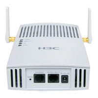
H3C WA2220X-AGP Installation Manual (79 pages)
WLAN WA2200 Series
Brand:
H3C
| Category:
Wireless Access Point
| Size: 1.51 MB
Table of Contents
Table of Contents
6
About this Manual
3
Chapter 1 Product Overview
11
Introduction
11
Figure 1-1 Positions of the WA2200 Series on the Network
11
Hardware Configuration
12
Figure 1-2 Appearance of the WA2200 Series
12
Table 1-1 Physical Dimensions of the WA2200 Series
12
Table 1-2 Protocols that each Model Supports and the Chassis Material
12
Leds
13
Figure 1-3 Leds on the H3C WA2210-AG/WA2220-AG
13
Table 1-3 Description of Leds on the H3C WA2210-AG/WA2220-AG
14
Figure 1-4 Leds on the H3C WA2220E-AG
15
Table 1-4 Description of Leds on the H3C WA2220E-AG
15
Figure 1-5 Leds on the H3C WA2210X-G
16
Figure 1-6 Leds on the WA2220X-AG and WA2220X-AGP
16
Interfaces
17
Table 1-5 Description of Leds on the H3C WA2210X-G, WA2220X-AG, and WA2220X-AGP
17
Table 1-6 Descriptions of Interfaces on WA2200 Series WLAN Access Points
18
Figure 1-7 Interfaces on H3C WA2210-AG/WA2220-AG(Indoor)
20
Figure 1-8 Interfaces on H3C WA2220E-AG(Enhanced)
21
Figure 1-9 Interfaces on H3C WA2210X-G/WA2220X-AG/WA2220X-AGP(Outdoor)
21
Chapter 2 Installation Preparations
23
Unpacking and Inspection
23
Table 2-1 List of Articles in the Package
23
Preparing Installation Tools
24
Examining the Installation Site
24
Installation Site Selection
24
Table 2-2 List of Installation Tools
24
Temperature and Humidity Requirements
25
Power Supply
25
Table 2-3 Environment Specifications
25
Table 2-4 Nominal Voltage and Frequency of the Low-Voltage AC Power Supply
25
Grounding and Lightning Protection
26
Table 2-5 Grounding and Lightning Protection Requirements
26
Chapter 3 Installation of Indoor Aps
27
Installation Flowchart
27
Determining the Installation Position
27
Figure 3-1 Installation Flowchart of an Indoor (Enhanced) AP
27
Installing the AP
28
Installing the Wall-Mounting Bracket on a Wall
28
Figure 3-2 Screw Hole Locations and Screw Hole Size
28
Installing the AP on the Wall-Mounting Bracket
29
Figure 3-3 Install the Wall-Mounting Bracket
29
Locking the AP Onto the Wall-Mounting Bracket (Optional)
30
Figure 3-4 Fix the Indoor AP Onto the Wall-Mounting Bracket
30
Figure 3-5 Fix the Enhanced AP Onto the Wall-Mounting Bracket
30
Figure 3-6 Lock the Indoor AP Onto the Wall-Mounting Bracket
31
Connecting the Power Supply
32
Local Power Supply
32
Figure 3-7 Lock the Enhanced AP Onto the Wall-Mounting Bracket
32
Power over Ethernet
33
Figure 3-8 Local Power Supply Connection
33
Figure 3-9 Poe Connection
33
Connecting the Network
34
Figure 3-10 Connect the AP to the Network
34
Chapter 4 Installation of Outdoor Aps
35
Installation Flowchart
35
Installing the AP
35
Figure 4-1 Installation Flowchart of the Outdoor Models
35
Figure 4-2 Installation Flowchart of the AP on a Wall
36
Figure 4-3 Wall-Mounting Bracket Structure and Positions of Screw Holes
37
Figure 4-4 Install the Outdoor AP on a Wall
39
Figure 4-5 Pole and Pole Base
40
Figure 4-6 Install the Outdoor AP on a Vertical Pole
40
Installing an Outdoor Antenna
41
Figure 4-7 Install the Outdoor AP on a Horizontal Pole
41
Figure 4-8 Install a Directional Outdoor Antenna on a Parapet
42
Figure 4-9 Install a Directional Outdoor Antenna on a Building Top Surface or Cement Pier
42
Figure 4-10 Install Omni Antennas
44
Figure 4-11 Install an Omni Antenna under a Special Environment
45
Connecting External Cables
46
Figure 4-12 Install an Omni Antenna on the AP Directly
46
Figure 4-13 Connect the Ethernet Electrical Interface to the Uplink Device
48
Figure 4-14 Connect the Ethernet Optical Interface to the Uplink Device
48
Figure 4-15 Exploded View of the Port Lightning Protector (Poe)
49
Figure 4-16 Ethernet Cable Connector
50
Table 4-1 RJ-45 Straight-Through Ethernet Cable Pinouts
50
Table 4-2 RJ-45 Crossover Ethernet Cable Pinouts
51
Figure 4-17 Insert the Ethernet Cable Connector into the Ethernet Interface
52
Figure 4-18 Connect a Fiber Cable
52
Powering on the AP
53
Figure 4-19 Connection of External Cables of the AP
54
Connecting the Network
55
Figure 4-20 Connection between the AP and Internet
55
Chapter 5 Software Setting
56
Working Mode Switching
56
Identifying the Current Working Mode
56
Switching from the FAT Mode to the FIT Mode
57
Switching from the FIT Mode to the FAT Mode
57
Setting up a Connection with the AP through the Console Interface
58
Telneting to the AP
58
Configuring Telnet
59
Configuring a FIT AP
60
Associating a FIT AP with the AC
60
Figure 5-1 Connection between a FIT AP and the AC
60
Configuring a FIT AP on the AC
61
Security Setting
63
Configuring a FAT AP
64
System Setting
64
Setting a System Name and the System Clock
65
Security Setting
66
Regulatory Compliance Information/Safety Information Sicherheitsinformationen 安全信息2-1
68
List of Figures
69
List of Tables
69
Chapter 1 Regulatory Compliance Information
70
Regulatory Compliance Standards
70
European Regulatory Compliance
71
EU Compliance Information
71
EU Country Restriction in 2.4Ghz Band
72
EU Country Restriction in 5Ghz Band
73
USA Regulatory Compliance
74
FCC Part 15
74
RF Requirements
74
Chapter 2 Safety Information Sicherheitsinformationen 安全信息2-1
77
General Requirements Allgemeine Anforderungen 通用要求2-1
77
Electricity Safety Elektrische Sicherheit 用电安全
78
Advertisement
Advertisement
Related Products
H3C WA2220-AG_INDOORDUALBAND
H3C WA2220-AG
H3C WA2220X-AG
H3C WA2220E-AG
H3C WA2210-AG_INDOORSINGLEBANDAP
H3C WA2210-AG
H3C WA2210X-G
H3C WA2200 Series
H3C WA2620-AGN
H3C WA2600 Series
H3C Categories
Switch
Network Router
Wireless Access Point
Control Unit
Gateway
More H3C Manuals
Login
Sign In
OR
Sign in with Facebook
Sign in with Google
Upload manual
Upload from disk
Upload from URL