
Related Manuals for H3C WA2210-AG_INDOORSINGLEBANDAP


Summary of Contents for H3C WA2210-AG_INDOORSINGLEBANDAP
- Page 1 H3C WA2200 Series WLAN Access Points Installation Manual Hangzhou H3C Technologies Co., Ltd. Manual Version: 6PW104-20091228...
- Page 2 Copyright © 2008-2009, Hangzhou H3C Technologies Co., Ltd. and its licensors H3C Technologies Co., Ltd., a subsidiary of 3Com Corporation. All Rights Reserved No part of this manual may be reproduced or transmitted in any form or by any means without prior written consent of Hangzhou H3C Technologies Co., Ltd.
-
Page 3: About This Manual
About This Manual Organization The H3C WA2200 Series WLAN Access Points Installation Manual is organized as follows: Chapter Contents Introduces the hardware configuration, appearances, and interfaces 1 Product Overview of the WA2200 series. Introduces the environment requirements, precautions, and tools for 2 Installation Preparations the installation of the WA2200 series. - Page 4 Repair Services, and Service Request. If you have trouble registering your product, please contact 3Com Global Services for assistance. Purchase Value-Added Services To enhance response times or extend warranty benefits, contact 3Com or your authorized reseller. Value-added services like Express and Guardian can include 24x7 telephone technical support, software upgrades, onsite assistance or advance hardware replacement.
- Page 5 Details about recent configuration changes, if applicable To send a product directly to 3Com for repair, you must first obtain a return authorization number (RMA). Products sent to 3Com, without authorization numbers clearly marked on the outside of the package, will be returned to the sender unopened, at the sender’s expense.
-
Page 6: Table Of Contents
Table of Contents 1 Product Overview ······································································································································1-1 Introduction ·············································································································································1-1 Hardware Configuration ··························································································································1-2 LEDs ················································································································································1-3 Interfaces·········································································································································1-5 2 Installation Preparations···························································································································2-1 Safety Precautions ··································································································································2-1 Preparing Installation Tools ····················································································································2-1 Examining the Installation Site················································································································2-2 Installation Site Selection ················································································································2-2 Temperature and Humidity Requirements ······················································································2-2 Power Supply ··································································································································2-2 Grounding and Lightning Protection································································································2-3 3 Installation of Indoor APs ·························································································································3-1 Installation Flowchart ······························································································································3-1... -
Page 7: Product Overview
The models listed in this manual are not applicable to all regions. Please consult the local agents for the models applicable to your region. Product Overview Introduction The H3C WA2200 series WLAN access points (hereinafter referred to as the WA2200 series) are developed by Hangzhou H3C Technologies Co., Ltd. -
Page 8: Hardware Configuration
Figure 1-2 Appearance of the WA2200 series Table 1-1 Physical dimensions of the WA2200 series Model Physical dimensions (H×W×D) Weight WA2210-AG/WA2220-AG, (indoor) 40×166×118 mm (1.57×6.54×4.65 in.) 0.5 kg (1.10 lb) WA2210X-G/WA2220X-AG, (outdoor) 76×245×245 mm (2.99×9.65×9.65 in.) 2 kg (4.41 lb) Hardware Configuration The four models of the WA2200 series have different radio frequencies (RFs) and structures. -
Page 9: Leds
The WA2200 series have extraordinary radio frequency (RF) performance and provide consummate service functions. With IP66 degree of protection, the outdoor models can be directly deployed outdoors to simplify the installation. The models of the WA2200 series are designed for application in various environments. - Page 10 The WA2210-AG is a single-RF device. The 11a and 11b/g LEDs cannot be on or flash at the same time. WA2210X-G/WA2220X-AG Figure 1-4 LEDs on the WA2210X-G Figure 1-5 LEDs on the WA2220X-AG Table 1-4 Description of LEDs on the WA2210X-G/WA2220X-AG Color Meaning Displays the power supply status:...
-
Page 11: Interfaces
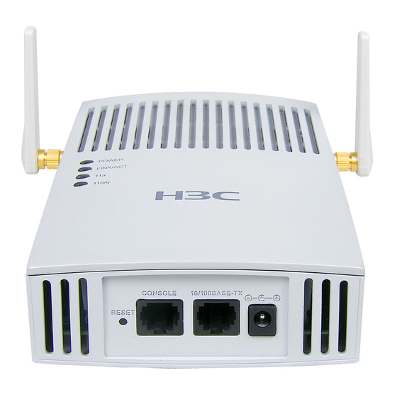
Color Meaning Displays the status of the optical interface: On: The link on the optical interface is up. 100BASE-FX Yellow Off: The link on the optical interface is down. Flashing: Data is being transmitted or received. Displays the wireless link status: Off: The wireless link is not initialized or the link is faulty. - Page 12 Table 1-5 Descriptions of interfaces on WA2200 series WLAN access points Standards and Model Interface Description protocols WA2210-AG: Main antenna interface, Antenna 2.4/5-GHz IEEE802.11b/g interface 1 WA2220-AG: 2.4-GHz antenna interface Console The console interface is used for device RS/EIA-232 interface configuration and management.
- Page 13 Interfaces provided by WA2210-AG/WA2220-AG Figure 1-6 Interfaces on WA2210-AG/WA2220-AG Top view Bottom view Antenna interface 1 Antenna interface 2 WA2210-AG is a single-RF device. Viewed from the front, the antenna interface on the left (antenna interface 1 in Figure 1-6) is the main antenna interface, while the one on the right (antenna interface 2 in Figure 1-6) is the auxiliary antenna interface.
- Page 14 Interfaces provided by WA2210X-G/WA2220X-AG Figure 1-7 Interfaces on WA2210X-G/WA2220X-AG Right view(WA2220X-AG) Bottom view(WA2210X-G/WA2220X-AG) Antenna Consol 10/100BASE-TX Grounding 100BASE-FX Antenna interface1 interface screw interface2 WA2210X-G is a single-RF device and provides no 5-GHz antenna interface.
-
Page 15: Installation Preparations
Installation Preparations This chapter describes the preparations for WA2200 installation, including preparation of installation tools, environment examination, and unpacking & inspection. Safety Precautions Installation and removal of the unit and its accessories must be carried out by qualified personnel. You must read all of the Safety Instructions supplied with your device before installation and operation. -
Page 16: Examining The Installation Site
The WA2200 series can be powered through 802.3af-compliant power over Ethernet (PoE) (except WA2220X-AG) or an external power adaptor. For details see the Table 2-3. Outside China it is recommended that this unit be PoE powered. Please see the H3C/3Com product catalogues for a range of 802.3af compatible power sources. -
Page 17: Grounding And Lightning Protection
Connect the adapter’s power jack to the AP power interface. H3C WA2200 series access points (except WA2220X-AG) can accept power from a PoE Please see the H3C/3Com Power over Ethernet (PoE, power source. product catalogues for a range IEEE 802.3af standard) power of 802.3af compatible power... - Page 18 Item Requirements Use a power cord with a protective earth (PE). Do not use a power cord with Power only an L line and an N line. grounding The neutral line of the power cord should not be connected with the PGND of (AC) other communications equipment.
-
Page 19: Installation Of Indoor Aps
Installation of Indoor APs You can directly place an indoor model (including the enhanced model) on a desk. The rubber feet on the bottom of the AP help you to place it horizontally. Or you can fix it onto a wall by using the wall-mounting bracket. -
Page 20: Installing The
Installing the AP The following describes how to install the AP on a wall. Installing the Wall-Mounting Bracket on a Wall Installing the AP on the Wall-Mounting Bracket Locking the AP onto the Wall-Mounting Bracket (Optional) Installing the Wall-Mounting Bracket on a Wall Follow these steps to install the wall-mounting bracket on a wall: Step1 Drill holes 6 mm (0.24 in) in diameter on the wall where the AP should be mounted. -
Page 21: Installing The Ap On The Wall-Mounting Bracket
Figure 3-3 Install the wall-mounting bracket When installing the wall-mounting bracket, position it so that the arrowhead points upward. Installing the AP on the Wall-Mounting Bracket Follow these steps to install the AP on the wall-mounting bracket: Step1 Align the AP with the hooks on the wall-mounting bracket and hang the AP on the bracket (see (1) in Figure 3-4). -
Page 22: Locking The Ap Onto The Wall-Mounting Bracket (Optional)
Figure 3-4 Fix the indoor AP onto the wall-mounting bracket Expansion screw Hock Locking the AP onto the Wall-Mounting Bracket (Optional) The indoor APs have a security slot on the top, which can be used to lock the AP onto the wall-mounting bracket to prevent theft. -
Page 23: Connecting The Power Supply
Figure 3-5 Lock the indoor AP onto the wall-mounting bracket The lock is user supplied. Connecting the Power Supply Local Power Supply Connect the AP to the power adapter and then to the power source, as shown in Figure 3-6. -
Page 24: Power Over Ethernet
Figure 3-6 Local power supply connection Power interface Power adapter Power over Ethernet If the uplink device of the AP is a PoE switch or the like, use an Ethernet cable to directly connect the Ethernet interface of the AP to the PoE device. Figure 3-7 PoE connection In the case of PoE, you do not need to connect the power interface to a power source. - Page 25 Figure 3-8 Connect the AP to the network Wireless station Internet Switch WA2200 Wired station Wired station...
-
Page 26: Installation Of Outdoor Aps
Installation of Outdoor APs The outdoor models of the WA2200 series are H3C WA2210X-G and H3C WA2220X-AG. You can select an appropriate model according to the actual requirement. The two outdoor models are waterproof, dustproof, and lightningproof. Installation Flowchart You can install your outdoor AP on a wall or a pole. As a wireless device, the installation location directly affects the coverage and performance of wireless signals. - Page 27 Figure 4-2 Installation flowchart of the AP on a wall Start Mark Drill holes Install anchors Fix the wall-mounting bracket Fix the AP Mark Step Operation Put the wall-mounting bracket on the installation position against the wall. Mark three expansion screw holes on the wall. For the distance (in mm) between the expansion screw holes, see Figure 4-3.
- Page 28 Figure 4-3 Wall-mounting bracket structure and positions of screw holes 195.0 135.0 80.0 70.0 40.0 220.0 Drill holes Step Operation Use a percussion drill with a 6-mm (0.24-in) bit to drill holes on the three markings. Observe the following precautions when drilling: Hold the drill handle with both hands, with the bit perpendicular to the wall surface, and prevent wall damage or tilted holes.
- Page 29 Step Operation Put an anchor into each hole vertically. Tap the flat end of the anchor with a rubber hammer until the anchor is flush with the wall surface. Fix the wall-mounting bracket Step Operation Align the three holes in the wall-mounting bracket with the anchors and insert three expansion screws through the installation holes into the anchors.
- Page 30 with an outer diameter of 60 to 110 mm (2.36 to 4.33 in) through the fixing support. The mounting plate and the V-shaped bracket are fixed through the self-clinching bolt and a nut, as shown in Figure 4-5. Figure 4-5 Mounting plate and V-shaped bracket You can adjust the angle of the AP as needed.
- Page 31 Figure 4-7 Pole and pole base Step4 Fix the mounting plate onto one V-shaped fixing bracket with a self-clinching bolt. Step5 Fix the pair of V-shaped fixing brackets on a vertical or horizontal pole with tie-bar bolts, flat washers, spring washers, and nuts (see Figure 4-8 or Figure 4-9). Figure 4-8 Install the outdoor AP on a vertical pole...
-
Page 32: Installing An Outdoor Antenna
Figure 4-9 Install the outdoor AP on a horizontal pole Step6 Fix the AP onto the mounting plate with screws (see the dashed line and arrow in Figure 4-8 or Figure 4-9). You can first install the fixing support onto the pole and then the AP onto the mounting plate, or vice versa. - Page 33 Follow these steps to install a pole on a parapet: Step1 Weld the lightning rod onto the tip of the pole. Step2 Install the pole on a parapet or cement pier. Step3 Use a 40 × 4 mm (1.57 × 0.16 in) flat steel to connect the pole to the ground grid Step4 Use pole-mounting brackets to install the directional outdoor antenna on the pole.
- Page 34 If there are parapets around the building top and the parapet height is less than 1200 mm (47.24 in), fix one point of the pole to the parapet with one expansion bolt and the other point to the building top surface with another expansion bolt, and fix the directional outdoor antenna onto the pole with pole-mounting brackets (see the right diagram in Figure 4-10).
- Page 35 Figure 4-13 Install an omni antenna under a special environment Lightning rod 45° Omni outdoor antenna > 1000mm Clamp Angle steel Antenna ploe In Figure 4-13, the antenna pole is welded with two angle steels to the lightning rod pole, instead of a cement pier.
-
Page 36: Connecting External Cables
Figure 4-14 Install an omni antenna on the AP directly After the omni antenna is installed on the AP, the antenna should be at least one meter away from the pole or other metal objects. The outdoor AP and the feeder lightning arrester are each equipped with a 3-meter-long grounding cable. - Page 37 Step2 Connect one end of the RF cable to the feeder lightning arrester and the other end to the outdoor antenna. Step3 Wrap each joint with insulation tape first, and then with waterproof tape. It is recommended to install a feeder lightning arrester on each antenna interface and ground it well.
- Page 38 Figure 4-16 Connect the Ethernet optical interface to the uplink device Figure 4-17 Exploded view of the port lightning protector (PoE) If the uplink device is a PoE switch, no port lightning protector or power adapter is required. It is not recommended to provide power to the AP using a PoE switch.
- Page 39 Since an Ethernet cable needs to pass through a waterproof cover for waterproof purpose (an Ethernet cable with an RJ-45 connector is unable to pass through), you need to prepare an Ethernet cable connector on site. Usually a category-5 or enhanced category-5 twisted pair cable is adopted. Figure 4-18 shows an Ethernet cable connector.
- Page 40 Pin of RJ-45 Category-5 twisted pair Pin of RJ-45 Signal Signal direction connector cable connector White (green) — Blue — — White (blue) — Green — White (brown) — — Brown — When distinguishing or preparing these two types of Ethernet cables, you can refer to the above tables.
- Page 41 Connecting an optical fiber Be sure to follow the instructions below when connecting a fiber cable. Otherwise, the AP may get damaged. When connecting the AP to the remote device through a fiber cable, use an appropriate SFP module. The SFP modules provided by H3C can be used outdoor. These SFP modules use single-mode optic fibers and have a transmission distance of 15 km (9.32 miles).
- Page 42 The fiber cable is a 10-meter tail fiber with a waterproof cover. One end of the fiber is an LC connector with a waterproof joint, and the other end is an SC connector, which can be connected to a fiber or device.
-
Page 43: Powering On The Ap
If a PoE switch is used to supply power, no port lightning protector or power adapter is required. It is not recommended to provide power to the AP using a PoE switch over a long distance. To supply power to the AP through a port lightning protector, you need to connect the port lightning protector to the switch. -
Page 44: Connecting The Network
Figure 4-22 Connection of external cables of the AP Outdoor antenna RF cable Outdoor antenna Grounding cable for feeder lightning arrester Grounding cable Ethernet cable Fiber cable Connecting the Network In practice, the AP can be connected to the Internet or a MAN through an Ethernet interface, as shown in Figure 4-23. - Page 45 Figure 4-23 Connection between the AP and Internet (the AP works in the FAT AP mode) A special outdoor waterproof Ethernet cable is required to connect the AP and waterproof treatment should be made to the Ethernet cable at the outlet of the chassis. 4-20...
Need help?
Do you have a question about the WA2210-AG_INDOORSINGLEBANDAP and is the answer not in the manual?
Questions and answers